chemical engineering research and design 88(2010)1515–1522
Contents lists available at ScienceDirect
Chemical Engineering Research and
Design
j o u r n a l h o m e p a g e :w w w.e l s e v i e r.c o m /l o c a t e /c h e r
d
A novel concept reactor design for preventing salt deposition in supercritical water
Dong H.Xu,Shu Z.Wang ?,Yan M.Gong,Y .Guo,Xing Y .Tang,Hong H.Ma
State Key Laboratory of Multiphase Flow in Power Engineering,Xi’an Jiaotong University,Xianning West Road 28,Xi’an,Shaanxi Province 710049,China
a b s t r a c t
Reactor plugging and corrosion are the key problems which hinder commercial applications of supercritical water oxidation and gasi?cation,and can be ef?ciently overcome by preventing salt deposition on internal surface of reactor.In this work the problems caused by salt deposition and the correspondingly main solutions are further reviewed objectively.A novel reactor is designed and manufactured with a feed rate of about 100L/h for sewage sludge treatment.The reactor combines the characteristics of Modar reactor and transpiring wall reactor for the ?rst time,which is expected to prevent reactor plugging and corrosion as well as to decrease catalyst deactivation rate.The reactor is the core equipment of the ?rst pilot-scale plant for supercritical water oxidation in China.Further optimizations of reactor con?guration and operational parameters need plenty of experiments and/or a long-time test with sewage sludge in the subsequent work.
?2010The Institution of Chemical Engineers.Published by Elsevier B.V .All rights reserved.
Keywords:Plugging;Corrosion;Salt deposition;Supercritical water;Reactor design
1.Introduction
Supercritical water (SCW:T >374.15?C,P >22.1MPa)possesses specially physical and chemical properties such as high diffu-sivity,low viscosity,low dielectric constant and small amount of hydrogen https://www.doczj.com/doc/b18321732.html,anic matter and oxygen can be dis-solved in SCW with any ratio under high enough pressure condition while the solubility of inorganic salt in SCW is extremely low.Therefore,these properties are bene?cial to reduce resistance of mass and heat transfer and to separate salt from SCW .As an attractive media for regulating chemical reaction process and performing salt separation process,SCW has been paid more attentions since the early 1980s.
Supercritical water oxidation (SCWO)is de?ned as that organic matter is oxidized into harmlessly small molecu-lar compounds such as carbon dioxide,nitrogen,water and inorganic salt by excess oxidant in SCW .Supercritical water gasi?cation (SCWG),that is,organic matter takes place hydrol-ysis and pyrolysis reaction and so on in SCW to form a hydrogen-rich mixing gas.SCW is not only a solvent for organic matter but also a reactant for hydrogen production in SCWG [1].SCWO and SCWG have been identi?ed as promising
?
Corresponding author .
E-mail address:s z wang@https://www.doczj.com/doc/b18321732.html, (S.Z.Wang).
Received 3August 2009;Received in revised form 9December 2009;Accepted 8March 2010
technologies for harmless treatment and resource utilization of organic wastes by previous researches,respectively.
Some inorganic salt additives are added into reactor to decrease its corrosion rate [2–4].Partial alkali compounds are introduced from reactor inlet to neutralize acids formed in SCWO or employed as catalysts for hydrogen production in SCWG [5–9].These salts together with those contained in feed-stock may result in reactor plugging and increase corrosion rate of reactor because of their depositions.So it is required to prevent these salts from accumulating on the internal surface of reactor.Furthermore,there is hardly a long-life catalyst for organic waste containing plenty of salts in SCWO or SCWG till now.Kruse [10]reported it needed to remove salts precipitated before catalytic gasi?cation in SCWG for decreasing catalyst deactivation (poison and/or pollution)rate.It is also neces-sary to remove salts precipitated before catalytic oxidation in SCWO for the same reason.
Except for above different origins,salts also may come from reaction products.They will precipitate from SCW due to extremely low solubility and indicate complicated phase behaviors.Kawasaki’s group [11]reported that NaCl tended to agglomerate while KCl and CaCl 2tended to disperse and
0263-8762/$–see front matter ?2010The Institution of Chemical Engineers.Published by Elsevier B.V .All rights reserved.doi:10.1016/j.cherd.2010.03.003
1516chemical engineering research and design88(2010)1515–1522
deposit on the internal surface of reactor.In terms of whether or not the solid-state salt precipitated is promised to accu-mulate on reactor’s internal surface,the precipitated salt and the internal surface of reactor have two kinds of rela-tions in reactor[12].For the former case,salt removal can be accomplished by special instruments such as mechanical brushing,rotating scraper,reactor?ushing.For the latter case, it can be achieved by particular reactor designs and opera-tion means.They include reverse?ow tank reactor with brine pool,reversible?ow tubular reactor,transpiring wall reac-tor,centrifuge reactor,cross?ow?ltration,density separation, additive,high velocity?ow,homogeneous precipitation[12]. Moreover,extreme pressure is provided to avoid salt precip-itation in SCW.Marrone et al.[12]had objectively reviewed the properties of the above speci?c reactor con?gurations and operational approaches in commercial applications.Further-more,there are some other special reactor con?gurations such as cool wall reactor reported by Cocero and Martínez[13]and two pipes reactor introduced by Baura et al.[14].Whiting and Metha[15]and Calzavara et al.[16]set a moving-surface and a stirrer in their reactors,respectively.Príkopsk′y[17]installed a protective metal sleeve replaced easily to prevent salt from depositing on the internal surface of their axial reactor in SCWO.There is no doubt that no one-reactor design or opera-tion mean has been proven to be clearly superior to the others in all aspects.
In this work,previous investigations about salt deposition problems and three kinds of main reactor con?gurations for preventing salt deposition are further reviewed objectively.A novel reactor is designed and manufactured innovationally, which is utilized to treat sewage sludge by SCWO with a feed rate of about100L/h.The reactor is the core equipment of the ?rst pilot-scale SCWO plant constructed in China.Its design concepts for salt removal are presented concisely.
2.Salt deposition problems
Organic waste feedstock like sewage sludge commonly con-tains partial solid particles such as sand,clay and rust,which are much less prone to deposit on process surfaces than nascent inorganic salt particles in SCW[12].Thereby,in this article,salt is only de?ned as polar inorganic salt,excluding the solid particles above.
2.1.The in?uence of salt deposition on reactor
plugging
Solubility of salt is reduced evidently in SCW,which is usually lower than100mg/L.An approach based on the description of phase equilibrium between solid-salt phase and SCW phase was chosen to quantify solubility of salt by Leusbrock et al.
[18].Precipitated salt from SCW often forms agglomerates and deposits on internal surface of reactor.Reactor plugging will take place when salt deposition is left uncontrolled[19],espe-cially for a smaller diameter reactor with large and/or sticky salt crystals precipitated at a low?ow velocity[10].Kawasaki et al.[11]mentioned that reactor plugging occurred within 30min and15min for NaCl solutions of1.0wt%at450?C and500?C in SCWO,respectively.Sewage sludge was also proved to result in reactor plugging when treated in SCWG [20].If plugged,reactor has to be shut down,rinsed and then restarted,which will increase running cost and hinder com-mercial applications of SCWO and SCWG[10,19,21–23].Sticky salts described above mainly are calcium sulfate and alu-minum phosphate and so on,which can be rinsed by acid after reaction[24].Moreover,salt deposition also decreases heat transfer ef?ciency of reactor wall,increases pressure drop of reactor,and accelerates deactivation rate of catalyst. Experimental methods of investigating salt nucleation and growth in SCW had been reported by Armellini and Tester[25]. Hodes et al.[26]also had reviewed fundamental principles and researches concerning about salt precipitation in SCWO.Salt deposition is a key problem resulting in reactor plugging in SCWO or SCWG,and fundamental investigation needs to be conducted further in future.
2.2.The in?uence of salt deposition on reactor
corrosion
Compared with salt of ion form in subcritical water,salt in the form of molecule in SCW is relatively less corrosive [3,22,27–29].Salt precipitated in SCW mainly results chemi-cal corrosion through oxidation reaction.Salt in subcritical water mostly promotes power-chemical corrosion,and may result in intergranular corrosion starting from the edge of metal grain.Some salts are generated in SCWO process when organic matter includes heteroatoms such as chlorine,sulfur and phosphorus[12].They will severely erode reactor when depositing on the internal surface of reactor,especially reactor material is sensitive to these corrosive species.Reactor corro-sion should be prevented as much as possible,because it will lead to a short reactor life and a bad?uid treatment result. Nowadays,salt deposition is considered as an important factor causing reactor corrosion.
Due to the very low solubility of salt,two contradictions between preventing salt deposition and minimizing reactor corrosion rate are displayed as follows:First,preventing salt deposition needs high density SCW because it will exhibit a relatively improved solvent property for precipitated salts [30,31].However,minimizing corrosion rate requires low SCW density[30,32,33]for decreasing the content of salt in the form of ion.Oelkers and Helgeson[34]and Su et al.[35] controlled SCW density at less than250kg/m3in order to reduce reactor corrosion rate.Second,adding alkali com-pounds independently or in feedstock before reactor is helpful for inhibiting reactor corrosion,but the possibility of reactor plugging increases because of salt deposition[22].That is why some alkali compounds are delivered into reaction system from reactor outlet.
General atomics(GA)[36,37]utilized corrosion resistant material such as Hastelloy C276,titanium or platinum as the liner of their reactor.However,experiment results about destructing chemical weapons demonstrated that corrosion was very severe and the liner needed to be replaced after several hundreds of hours.Therefore,it necessary to prevent corrosive reaction?uid from contacting reactor’s internal sur-face no matter it is under supercritical or subcritical condition.
2.3.The in?uence of salt deposition on catalyst deactivation
Catalyst can be employed to decrease reaction temperature and pressure[38],compensate reaction dynamics[2],improve reactant conversion ef?ciency,and accelerate reaction rate. Catalysts served for SCWO conclude zeolite,CuO,MnO2, V2O5,nickel,platinum and so on.Heterogeneous catalysts such as nickel,ruthenium,ZrO2,active carbon,olivine can
chemical engineering research and design88(2010)1515–15221517
be chosen for catalytic SCWG.Catalyst deactivation caused by char deposition can be avoided ef?ciently because of the benign solvent and?ow properties of SCW.But these catalysts may be poisoned and/or polluted quickly by pre-cipitated salts[20,39–41]in SCW for real feedstock.It is also dif?cult to replace catalyst in traditional reactor con?gura-tion.That may be why Savage[42]has reported that no catalyst is implemented commercially for catalytic SCWO for organic waste treatment or catalytic SCWG for renew-able energy production.Thereby,it is important to separate these precipitated salts before they contact heterogeneous catalyst.
2.4.Salt separation technology
Nowadays,there are a series of well-developed technologies for preventing salt deposition.Most of them attempt to avoid reactor plugging without salt separation,in which salt still is contained in reactor ef?uent.In fact,salt separation from SCW is even considered as a key issue in SCWO and SCWG by Peter-son et al.[23].It should be conducted for obtaining cleaner reactor ef?uent to reutilize and decreasing catalyst deacti-vation rate.Theoretically,salt separation can be performed before reaction,in reaction or after reaction.However,it is not ?t to be conducted by traditional methods such as distillation, ion exchange,electrodialysis,reverse osmosis before reaction and/or in reaction.It is due to the complex feedstock features and the critical reaction conditions.
Salt separation by centrifugal forces can be accomplished by centrifuge reactor[43],hydrocyclone[44]or a reactor with rotational spin[45].Nonetheless,these apparatuses eventually may be plugged because of the deposition of sticky salt[12].Additionally,salt separation was also per-formed in the preheating step using two representative bio-re?nery residues before catalytic reaction by Elliott[46]. In view of the particular solubility property of salt in SCW, the ideal and ef?cient approach for salt separation may be to utilize the property in combined with other sepa-ration mean like?ltrating.Of course,taking into account operational economics,it is not necessary to separate salt completely.
2.5.Three kinds of main reactor con?gurations for preventing salt deposition
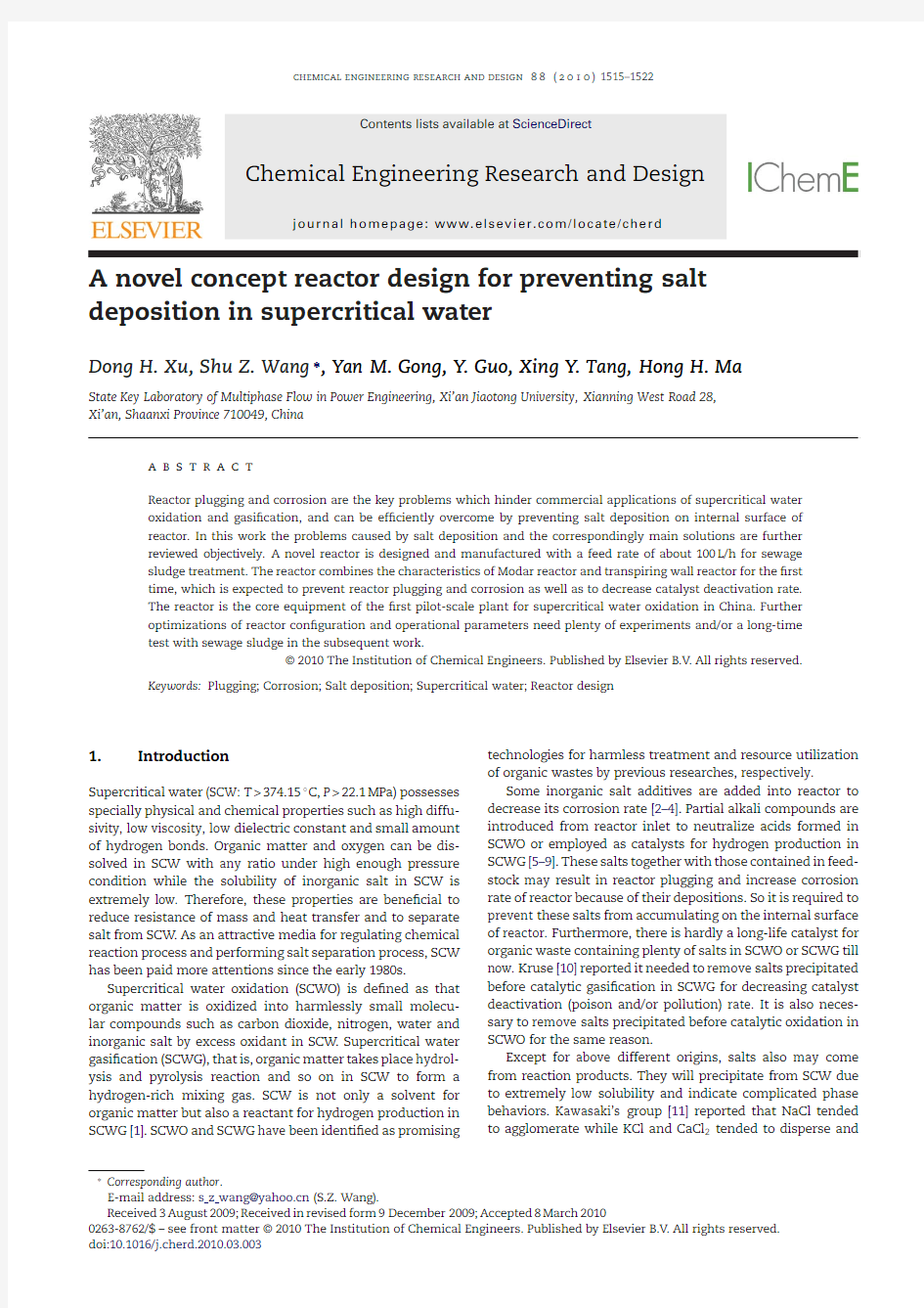
Modar reactor[47]or its variation[48]belongs to a reverse?ow tank reactor with brine pool,which separates/removes salt by SCW property,as shown in Fig.1.Precipitated salts under supercritical condition fall down into the subcritical zone at the bottom of reactor by gravity,inertia and forced convection. Modar reactor has overcome the three disadvantages of tubu-lar reactor,which are too long structure size,not suitable for dealing with salt-containing feedstock,and easy to be plugged. However,due to the low falling velocity of small particle salt and the disturbance at the vertical direction,salt deposition is easy to take place on the internal surface of Modar reac-tor in supercritical zone[35].Moreover,Modar reactor may be eroded severely because its internal surface directly contacts corrosive reaction?uid.
Cool wall reactor[13]and transpiring wall reactor[49–52] can help to solve salt deposition problems existing in Modar reactor.These two kinds of reactors are divided into pressure-bearing wall and non-load-bearing wall.For cool wall reactor, precipitated salts are re-dissolved in a subcritical water
?lm Fig.1–Schematic diagram of reverse?ow tank reactor[12].
on the internal surface of non-load-bearing wall.The?lm is formed by low temperature feedstock cooling the non-load-bearing wall.However,severe corrosion still takes place because of the contaction between corrosive reaction?uid and internal surface of non-load-bearing wall.When scale on the internal and external surfaces of non-load-bearing wall is left uncontrolled,cool wall reactor will not continue to work nor-mally since heat transfer ef?ciency reduces drastically.
Transpiring wall reactor can not only prevent salt depo-sition but also decrease reactor corrosion rate through a porous transpiring wall element.Clean water?ows across the porous wall to form a protective?lm to continuously dilute corrosive species,re-dissolve precipitated salt parti-cles and/or sweep them away from the internal surface of reactor.The transpiring wall(non-load-bearing wall)can be made of porous ceramic[53],sintered metal[50],or many thin and porous metal layers/platelets bonded together[54,55]. The operational characteristics of transpiring wall reactor had been tested for a long time by some researchers[49,50,56].It was found that the concentrations of iron,nickel,chromium ions in reactor ef?uent were very low,which proved corro-sion rate of transpiring wall reactor was low.Fauvel et al.
[51]and Haroldsen et al.[57]also veri?ed that transpiring wall reactor had a good corrosion resistance property.Thus, it can be claimed that transpiring wall reactor is the best reactor con?guration for minimizing reactor corrosion rate at present.Nonetheless,plenty of energy is required to preheat the transpiration water entering into reactor[35].The pressure difference of two sides of transpiring wall should be adjusted at a suitable range since it has a bad mechanical property.
3.A novel reactor design
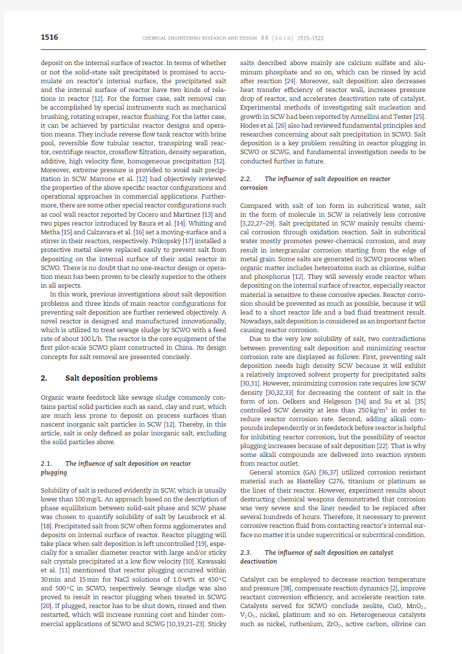
On the basis of summarizing characteristics of previously main reactor con?gurations,together with our experimen-tal results and design experiences of bench-scale SCWO plant for sewage sludge treatment reported elsewhere,a novel con-cept reactor is designed and manufactured for treating sewage sludge by SCWO,as shown in Fig.2.
1518chemical engineering research and design88(2010)
1515–1522
Fig.2–Schematic diagram of TWM reactor for treating sewage sludge by SCWO.(1)Spherical head;(2)pressure measurement tube;(3)temperature measurement tube;(4) cooling spiral coil;(5)catalyst box;(6)support ring;(7)
eight-square cushion;(8)top cover;(9)?xed platform;(10) cooling cover;(11)?lter;(12)center pipe;(13)annular water box;(14)pressure-bearing wall;(15)ear base;(16) transpiring wall;(17)locating ring;TI:temperature indication;PI:pressure indicate.
3.1.Reactor con?guration
The novel reactor owns characteristics of transpiring wall reactor and Modar reactor for the?rst time,which is sim-ply nominated as“TWM reactor”.Similar to Modar reactor, TWM reactor is also divided into supercritical zone above and subcritical zone below.Precipitated salts under supercritical condition fall down into the subcritical zone(formed by pump-ing into quench water)and are re-dissolved.Clean?uid after removed salts,?ows toward top outlet of reactor by the differ-ences of density and?ow resistance.The valves equipped on pipe lines of top and bottom outlets of reactor,which can be seen in pilot-scale plant,are used to regulate?ow rate of?uid at top outlet.Dirt?uid?ows out TWM reactor from its
bottom Fig.3–Schematic diagram for cooling top cover of TWM reactor.(1)Top cover;(2)temperature measurement hole;(3)?xed platform;(4)cooling cover;(5)transpiring wall.
outlet,which contains large amount of salts and solids.The ?ow pattern of TWM reactor is helpful for eliminating natural convection effects which were mentioned by Wellig’s group [52]for transpiring wall reactor.
Modar reactor wall is replaced by a porous transpiring wall and a pressure-bearing wall is set to surround it to form fundamental con?guration of TWM reactor.Clean and cool transpiration water is pumped into TWM reactor and forms a protective?lm on the internal surface of transpiring wall. TWM reactor con?guration is expected to prevent salt deposi-tion and decrease corrosion rate.
3.2.Main parts in TWM reactor
Center pipe of Modar reactor is comparatively thin and long [47,48],while transpiring wall reactor has no center pipe.Tran-spiring wall reactor sets a complicated nozzle for mixing of oxidant and organic matter[58–60].For TWM reactor,the mix-ing of oxygen and sewage sludge preheated is accomplished by a specially simpli?ed mixer equipped on the pipe line of reactor inlet.Center pipe is inserted into the reactor deeply and its diameter is big enough to avoid plugging.Reactants in center pipe are further preheated by high temperature?uid around or by reaction heat yielded through partial oxidation. Ideally,the mixture of oxygen and sewage sludge just reaches supercritical temperature at the outlet of center pipe.It is bet-ter to maintain subcritical temperature in center pipe because salt will not deposit on the internal surface of center pipe.The center pipe is set on a?xed platform by screw thread,which is easy to be replaced when plugged or eroded severely.
Traditional transpiring wall reactor generally is a tubu-lar reactor with a hydrothermal burner[52,61–63].However, no hydrothermal burner is set in TWM reactor in order to decrease design temperature of reactor and operation cost of sewage sludge SCWO treatment.When transpiring wall con-?guration is combined with Modar reactor,one problem is to design a suitable top cover for preventing salt deposition.In TWM reactor,top cover is cooled by low temperature water in a particular chamber formed between top cover and cooling cover,as displayed in Fig.3.The cooling cover is not porous so that the low temperature water will not fall into top reac-tion zone of reactor vertically.The low temperature water is transported into the chamber from two pores at top cover to quench the cooling cover and from a subcritical water?lm on the lower surface of cooling cover.Then it enters into top annular space between transpiring wall and pressure-bearing wall to be further used as transpiration water.In Fig.3,the two pores for transporting low temperature are not be seen because they are not set at the direction of top cover pro?le.
chemical engineering research and design88(2010)1515–15221519
Wellig[58]had checked the percolation rates of transpiring wall consisting of sintered metal at two different voidages and pressure conditions.In TWM reactor,transpiring wall with?l-tering precision of30?m and surface density of20%is made of sintered wire netting.Approximately100?oors of C276metal nettings with pore size of44?m and thickness of0.1mm are sintered together at high temperature condition to form the required transpiring wall.The inner diameter and length of cylindrical transpiring wall are300mm and1180mm,respec-tively.Moreover,the inner diameter of small end and length of conical transpiring wall are200mm and245mm,respectively. The cylindrical transpiring wall and the conical transpiring wall are connected through jointing by an especially sub-miniature electric welding machine to compose the whole transpiring wall.The whole transpiring wall is?xed in reactor by a support ring and a locating ring,and its expansion space is also provided.Transpiration water is adjusted at a subcriti-cal temperature for re-dissolving precipitated salt,decreasing design temperature of pressure-bearing wall and minimizing reactor’s manufacture cost.Transpiration water with a low velocity is required to avoid itself shaking possibly.Thus,four inlets are arranged in one of three?oors on the pressure-bearing wall to form a perfect?lm,and an annular water box is equipped for transpiration water distribution.It can be believed that the distribution is more homogeneous than that of reactor with a spindle transpiring wall and one transpiration water inlet[49–51].In TWM reactor,the transpiration water in the gap between transpiring wall and pressure-bearing wall does not contain oxidant(oxygen),which is different from the reactor designed by McGuinness[64].Moreover,it is also help-ful for decreasing corrosion rate of transpiring wall.A check valve will be equipped on the total pipe line of transpiration water inlet to ensure that reaction?uid will not conversely enter into the gap between pressure-bearing wall and tran-spiring wall.
In TWM reactor,an annular and porous catalyst box is?xed above the spout of center pipe to load catalyst.The catalyst box has no cover and its outer side is near to transpiring wall for avoiding salts deposition.Inert substance(like silicon dioxide) and catalyst are loaded at the bottom and top of the cata-lyst box,respectively.Reaction?uid enters into catalyst bed after salts have been removed at center pipe outlet and inert substance bed,which is bene?cial to slow deactivation rate of catalyst.Adding inert substance mainly aims to?ltrate and capture partly precipitated salts as well as to provide large sur-face for salt deposition.TWM reactor also can be developed to utilize as a?uidized bed reactor in future.
A cooling spiral coil is set in TWM reactor to control reaction temperature,which removes surplus heat in SCWO process by cooling water.The spiral coil is also equipped near to transpiring wall so that salt deposition on its outer surface can be prevented as much as possible.
3.3.Other aspects about TWM reactor
Components of feedstock should be con?rmed in order to choose proper material or materials cooperation for reactor manufacture.Because one kind of material is impossible to be suitable for all varieties of feedstocks[33,35,65].Hence,in TWM reactor,sewage sludge is chosen as a constant feedstock which contains moderate amount of salts.It is also found that nickel alloy and titanium metal have benign corrosion resistance performances under supercritical and subcritical conditions,respectively[22].Accordingly,the inner parts of TWM reactor such as transpiring wall,center pipe,sintered metal?lter,catalyst box,?xed platform,cooling cover are made of Hastelloy C276.The parts in subcritical zone are coated with Titanium metal,and the other outer pressure-bearing parts consist of stainless steel316.
In TWM reactor,removing salts will be conducted by SCW property before catalytic reaction.In order to ensure reactor ef?uent of top outlet is clean enough and can be recov-ered,a small-sintered metal?lter with pore size of30?m is?xed at the top outlet of reactor to further?ltrate small salt particles.The?uid at the bottom of reactor contains plenty of salts and solids,proper gradient on the internal surface of spherical head is provided for draining the dirt ?uid.Moreover,proper inner diameter and velocity are used to prevent plugging of the inlet and outlet pipe lines of TWM reactor.
In the following processes,reactor ef?uent of top outlet will be cooled and depressurized,then introduced into a gas–liquid separator for carbon dioxide and water separating.Ultimate liquid ef?uent will be recovered to utilize partially as transpi-ration water which is preheated up to a proper temperature by reactor ef?uent of high temperature.Quench water is pumped into reactor bottom to provide a protective water?lm,to form a subcritical zone re-dissolving precipitated salts,and to neutralize acids formed during reaction.Kawasaki et al.[11] presented that the bases such as KHCO3,K2CO3,KOH were ?t to utilize as neutralizing agents in SCWO,but NaOH was unsuitable for many conditions due to its precipitation char-acteristics.Hence,in TWM reactor,KOH is employed as the neutralizing agent,which is added into the quench water at the bottom of reactor.
Of course,reactor temperature distribution should be mea-sured and controlled exactly for reaction process,safety control and salt removal.In the reactor,some thermocouples are equipped at different positions to measure temperatures of reaction?uid,pressure-bearing wall and transpiring wall. As indicated in Fig.2,temperature measurement hole on pressure-bearing wall is drilled to the position approximate 1–2mm distance to the internal surface of pressure-bearing wall.Then a smaller hole is drilled to contact transpira-tion water for accurate measurement of pressure-bearing wall temperature.The temperatures of supercritical zone are adjusted by interior reaction heat and/or exterior heat sources provided by cooling water in cooling spiral coil and/or by electric heater set on the pipe line of reactor inlet.The temper-atures of pressure-bearing wall are controlled and regulated by temperature and/or?ow rate of transpiration water.The temperature of subcritical zone is controlled at the range of360–370?C by quench water.In addition,the seal of top cover is accomplished by eight-square cushion.It can be assembled and dismantled conveniently to replace catalyst, inert substance and inner parts of reactor.There is doubt that TWM reactor con?guration also can be referenced by reactor design for sewage sludge SCWG.The shell of the newly constructed reactor without top cover is shown as Fig.4.
TWM reactor is?t to deal with salt-containing feedstock but not the organic matter including plenty of heteroatoms. Because produced salts in reaction may plug inert substance bed and deactivate catalyst due to their deposition.Other-wise,inert substance bed and catalyst bed need to be rinsed or replaced frequently.Furthermore,the characteristics of heat and mass transfer about the reactor are relatively compli-cated.The paper is only introduced as a previous work,which
1520chemical engineering research and design88(2010)
1515–1522
Fig.4–Photograph of the shell of the newly constructed reactor without top cover.(1)Hoisting ring;(2,3,6,10,and 12)thermocouple joint;(4)annular water box;(5)ear base;
(7)brine ef?uent outlet;(8)pressure gauge joint;(9)quench water inlet;(11)branch pipe;(13)pressure-bearing wall.
mainly focuses on reactor design ideas and reactor con?gura-tion.Some conclusions above are obtained only by analyzing the reactor con?guration.A large amount of experimental test data will be provided in a subsequent work.
4.Conclusions and outlook
In this work,salt deposition problems and main reactor con-?gurations for avoiding them are further reviewed objectively.
A novel concept reactor for treating sewage sludge by SCWO is designed and manufactured.Some useful conclusions or thoughts are illustrated as follows.
It is necessary to prevent corrosive reaction?uid from contacting internal surface of reactor no matter it is under supercritical or subcritical condition.Nowadays,the best reac-tor con?guration for minimizing reactor corrosion rate needs to take advantage of transpiring wall element.
It is important to remove precipitated salts before they con-tact heterogeneous catalyst in SCWO.The ef?cient approach may be to utilize the particular SCW property in combination with other separation mean.
TWM reactor is developed to combine with the advantages of Modar reactor and transpiring wall reactor for solving the two key problems(reactor plugging and corrosion)in SCWO. Reactor temperature distribution is detected exactly by many measurement points for reaction process,safety control and salt separation.Transpiration water is distributed homoge-neously by many inlets to form a properly thick?lm on the internal surface of reactor.Transpiration water and required heat for preheating it originate from reactor itself.Top cover is cooled by low temperature cooling water in a chamber designed specially.A porous catalyst box is equipped on the center pipe which is set on a?xed platform by screw thread. Before catalytic reaction,salt removal is conducted at the spout of center pipe and in inert substance bed.TWM reac-tor con?guration also can be referenced by reactor design for sewage sludge SCWG.
Some conclusions about TWM reactor are obtained only by analyzing its con?guration.They are required to be proved by plenty of experiments and/or a long-time test with sewage sludge.Further optimizations of reactor con?guration and operation parameters will be conducted in subsequent work.
Acknowledgement
The authors wish to acknowledge the?nancial supports from the National High Technology Research and Development Program of China through contract No.2006AA06Z313,the National Basic Research Program of China through contract No.2009CB220000,the Program for New Century Excellent Talents in University of Chinese Education Ministry through contract No.NCET-07-0678and the Opened Fund of Jiangsu Key Lab for Clean Energy and Power Machinery Engineering through contract No.QK08003.
References
García Jarana,M.B.,Sánchez-Oneto,J.,Portela,J.R.and Nebot Sanz,E.,2008,Martínez de la Ossa.E.J.Supercritical water
gasi?cation of industrial organic wastes.J.Supercrit.Fluids, 46:329–334.
Elliott,D.C.and Sealock,L.J.,Jr.,1985,Low temperature gasi?cation of biomass under pressure,In Overend,R.P.,
Milne,T.A.,&Mudge,L.K.(Eds.),Fundamentals of
thermochemical biomass conversion(Elsevier,London),pp.
937–950.(Elsevier,London).
Kriksunov,L.B.and MacDonald,D.D.,1995,Corrosion in supercritical water oxidation systems:a phenomenological analysis.J Electrochem Soc,142:4069–4078.
Peterson,A.A.,Vontobel,P.,Vogel,F.and Tester,J.W.,2009, Normal-phase dynamic imaging of supercritical-water salt
precipitation using neutron radiography.J Supercrit Fluids,49: 71–78.
Yoshida,T.and Oshima,Y.,2004,Partial oxidative and catalytic biomass gasi?cation in supercritical water:a promising?ow reactor system.Ind Eng Chem Res,43:4097–4104.
D’Jesus,P.,Boukis,N.,Kraushaar-Czarnetzki,B.and Dinjus,E., 2006,Gasi?cation of corn and clover grass in supercritical
water.Fuel,85:1032–1038.
Hao,X.H.,Guo,L.J.,Mao,X.,Zhang,X.M.and Chen,X.J.,2003, Hydrogen production from glucose used as a model
compound of biomass gasi?ed in supercritical water.Int J
Hydrogen Energy,28:55–64.
Kruse,A.and Gawlik,A.,2003,Biomass conversion in water at 330–410?C and30–50MPa.Identi?cation of key compounds for indicating different chemical reaction pathways.Ind Eng Chem Res,42:267–279.
Kruse,A.,Krupka,A.,Schwarzkopf,V.,Gamard,C.and Henningsen,T.,2005,In?uence of proteins on the
hydrothermal gasi?cation and liquefaction of biomass.1.
Comparison of different feedstocks.Ind Eng Chem Res,44:
3013–3020.
Kruse,A.,2009,Hydrothermal biomass gasi?cation.J Supercrit Fluids,47:391–399.
Kawasaki,S.I.,Oe,T.,Itoh,S.,Suzuki,A.,Sue,K.and Arai,K.,2007, Flow characteristics of aqueous salt solutions for applications in supercritical water oxidation.J Supercrit Fluids,42:
241–254.
Marrone,P.A.,Hodes,M.,Smith,K.A.and Tester,J.W.,2004,Salt precipitation and scale control in supercritical water
chemical engineering research and design88(2010)1515–15221521
oxidation—part B:commercial/full-scale applications.J
Supercrit Fluids,3:289–312.
Cocero,M.J.and Martínez,J.L.,2004,Cool wall reactor for supercritical water oxidation modelling and operation results.
J Supercrit Fluids,31:41–55.
Baura,S.,Schmidta,H.,Kr?merb,A.and Gerberb,J.,2005,The destruction of industrial aqueous waste containing biocides in supercritical water—development of the SUWOX process for the technical application.J Supercrit Fluids,33:
149–157.
Whiting,P.and Metha,A.H.,1996,Supercritical water oxidation of organics using a mobile surface,US Patent5543057. Calzavara,Y.,Joussot-Dubien,C.,T urc,H.A.,Fauvel,E.and Sarrade,S.,2004,A new reactor concept for hydrothermal
oxidation.J Supercrit Fluids,31:195–206.
Príkopsk′y,K.,2007,Characterization of continuous diffusion ?ames in supercritical water,Doctoral Thesis,No.17374,ETH Zurich,Switzerland,http://www.e-collection.ethz.ch. Leusbrock,I.,Metz,S.J.,Rexwinkel,G.and Versteeg,G.F.,2008, Quantitative approaches for the description of solubilities of inorganic compounds in near-critical and supercritical water.
J Supercrit Fluids,47:117–127.
Brunner,G.,2009,Near and supercritical water.Part II.Oxidative processes.J Supercrit Fluids,47:382–390.
Japan Gas Association,2002,Report on investigation of energy conversion technology for waste materials using supercritical water.http://www.ne-do.go.jp,10000264553.pdf[2005/2/11
accessed].
Schmieder,H.,Abeln,J.,Boukis,N.,Dinjus,E.,Kruse,A.,Kluth, M.,Petrich,G.,Sadri,E.and Schacht,M.,2000,Hydrothermal gasi?cation of biomass and organic wastes.J Supercrit Fluids, 17:145–53.
Kritzer,P.and Dinjus,E.,2001,An assessment of supercritical water oxidation(SCWO).Existing problems,possible solutions and new reactor concepts.Chem Eng J,83:
207–214.
Peterson,A.A.,Vontobel,P.and Vogel,J.W.,2008,In situ visualization of the performance of a supercritical-water salt separator using neutron radiography.J Supercrit Fluids,43:
490–499.
Zhang,P.,Wang,J.C.,Zhang,X.D.,Liu,X.W.,Xia,Y.J.and Li,Z.Y., 2003,Progress on waste water treatment of supercitical water oxidation.Environ Prot Sci,29:15–17.
Armellini,F.J.and Tester,J.W.,1991,Experimental methods for studying salt nucleation and growth from supercritical water.
J Supercrit Fluids,4:254–264.
Hodes,M.,Marrone,P.A.,Hong,G.T.,Smith,K.A.and Tester,J.W., 2004,Salt precipitation and scale control in supercritical
water oxidation—Part A:fundamentals and research.J
Supercrit Fluids,29:265–288.
Kritzer,P.,Boukis,N.and Dinjus,E.,1998,Corrosion of alloy625 in aqueous chloride and oxygen containing solutions.
Corrosion,54:824–834.
Boukis,N.,Franz,G.,Friedrich,C.,Habicht,W.and Ebert,K.,1996, Corrosion screening tests with Ni-based alloys in supercritical water containing hydrochloric acid and oxygen.Proc ASME Heat Transfer Division,4:156–163.
Tester,J.W.,Holgate,H.R.,Armellini,F.J.,Webley,P.A.,Killilea, W.R.,Hong,G.T.and Barner,H.E.,1993,Supercritical water
oxidation,in Emerging Technologies in HazardousWaste
Management III,ACS Symposium Series,vol.518,Tedder,W.D.
and Pohland,F.G.,Pohland,F.G.(eds)American Chemical
Society,Washington,DC,,pp.35–76.
Kritzer,P.,2004,Corrosion in high-temperature and supercritical water and aqueous solutions:a review.J Supercrit Fluids,29: 1–29.
Oelkers,E.H.and Helgeson,H.C.,1993,Multiple ion association in supercritical aqueous solutions of single electrolytes.Science, 261:888–896.
Brock,E.E.,Oshima,Y.,Savage,P.E.and Barker,J.R.,1996, Kinemics and mechanism of methanol oxidation of
supercritical water.J Phys Chem,100:
15834–15842.Kritzer,P.,Boukis,N.and Dinjus,E.,1999,Factors controlling corrosion in high-temperature aqueous solutions:a
contribution to the dissociation and solubility data
in?uencing corrosion processes.J Supercrit Fluids,15:
205–227.
Oelkers,E.H.and Helgeson,H.C.,1993,Multiple ion association in supercritical aqueous solutions of single electrolytes.Science, 261:888–891.
Su,D.H.,Zheng,Z.,Wang,Y.and Tang,D.Y.,2003,Supercritical water oxidation technology.Ind Water Treat,23:
10–14.
National Research Council.,(2005).Interim Design Assessment for the Blue Grass Chemical Agent Destruction Pilot Plant.(The
National Academies Press),p.1–94
National Research Council.,(2006).Letter Report of Review and Assessment of the Proposals for Design and Operation of Designated Chemical Agent Destruction Pilot Plants.(The National
Academies Press),p.1–162
Poliakoff,M.,Darr,J.A.,Ikehans,T.and Cabanas,A.,1999,The synthesis of crystalline metal oxide particles in sub-and
supercritical water mixtures,In Proceedings of the6th Meeting on Supercritical Fluids Nottingham,UK,Institute National
Polytechnique De Lorraine(INPL),Vandoeuvre Cedex,France,, pp.483–490.
Antal,M.J.,Allen,S.G.,Schulman,D.,Xu,X.and Divilio,R.J.,2000, Biomass gasi?cation in supercritical water.Ind Eng Chem Res, 39:4040–4053.
Ro,K.S.,Cantrell,K.,Elliott,D.and Hunt,P.G.,2007,Catalytic wet gasi?cation of municipal and animal wastes.Ind Eng Chem Res,46:8839–8845.
Waldner,M.H.,Krumeich,F.and Vogel,F.,2007,Synthetic natural gas by hydrothermal gasi?cation of biomass:selection
procedure towards a stable catalyst and its sodium sulfate
tolerance.J Supercrit Fluids,43:91–105.
Savage,P.E.,2009,A perspective on catalysis in sub-and supercritical water.J Supercrit Fluids,47:407–414.
Reid,A.F.and Halff,A.H.,1995,Method for separation and removal of impurities from liquids,U.S.Patent5425883.
Grif?th,J.W.and Raymond,D.H.,2002,The?rst commercial supercritical water oxidation sludge processing plant.Waste Manage,22:453–459.
Titmas,J.A.,1986,Method and apparatus for conducting chemical reactions at supercritical conditions,U.S.Patent4594164. Elliott,D.C.,2008,Catalytic hydrothermal gasi?cation of biomass.
Biofuels Bioprod Biore?n,2:254–265.
Cohen,L.S.,Jensen,D.,Lee,G.and Ordway,D.W.,1998, Hydrothermal oxidation of Navy excess hazardous materials.
Waste Manage,18:539–546.
Huang,C.Y.,1992,Apparatus and method for supercritical water oxidation,U.S.Patent5100560.
T urbosystems Engineering,2008,The Transpiring Wall Reactor (“TWR”).https://www.doczj.com/doc/b18321732.html,/
summitresearch/sumscw4.htm.
Abeln,J.,Kluth,M.,Petrich,G.and Schmieder,H.,2000,Waste treatment by SCWO using a pipe and a transpiring wall
reactor,Forschungszentrum Karlsruhe.http://www.
https://www.doczj.com/doc/b18321732.html,/summitresearch/Kochi-revised1.pdf. Fauvel,E.,Joussot-Dubien,C.,Tanneur,V.,Moussiere,S., Guichardon,P.,Charbit,G.and Charbit,F.,2005,A porous
reactor for supercritical water oxidation:experimental results on salty compounds and corrosive solvents oxidation.Ind Eng Chem Res,44:8968–8971.
Wellig,B.,Lieball,K.and Rudolf Von Rohr,P.,2005,Operating characteristics of a transpiring-wall SCWO reactor with a
hydrothermal?ame as internal heat source.J Supercrit Fluids, 34:35–50.
Lee,H.C.,In,J.H.,Lee,S.Y.,Kim,J.H.and Lee,C.H.,2005,An anti-corrosive reactor for the decomposition of halogenated hydrocarbons with supercritical water oxidation.J Supercrit Fluids,36:59–69.
Mueggenburg,H.H.,1995,Supercritical water oxidation reactor with wall conduits for boundary?ow control,U.S.Patent
5387398.
1522chemical engineering research and design88(2010)1515–1522
Ahluwalia,K.S.,1996,Internal platelet heat source and method of use in a supercritical water oxidation reactor,U.S.Patent
5571424.
T urbosystems Engineering,2008,Closed-Cycle SCWO Processing System,https://www.doczj.com/doc/b18321732.html,/
summitresearch/sumscw4.htm.
Haroldsen,B.L.,Ariizumi,D.Y.,Mills,B.E.,Brown,B.G.and Greisen,D.,1996,Transpiring wall supercritical water
oxidation reactor salt deposition studies,Sandia National
Laboratories,Report No.SAND96-8255.
Wellig,B.,2003,Transpiring wall reactor for supercritical water oxidation,Doctoral Thesis No.15038,ETH Zurich,
Switzerland,http://www.e-collection.ethz.ch. Mueggenburg,H.H.,Rousar,D.C.and Young,M.F.,1998,Injector for SCWO reactor,U.S.Patent5804066.
Rice,S.F.,Wu,B.C.and Winters,W.S.,2000,Engineering modeling of the pine bluff arsenal supercritical water oxidation reactor.
Sandia National Laboratories,Report No.SAND2000-8656C. Serikawa,R.M.,Usui,T.,Nishimura,T.,Sato,H.,Hamada,S.and Sekino,H.,2002,hydrothermal?ames in supercritical
oxidation:investigation in a pilot scale continuous reactor.
Fuel,81:1147–1159.
Weber,M.,Wellig,B.,Lieball,K.and Rudolf von Rohr,P.,2001, Operating transpiring-wall SCWO reactors:characteristics
and quantitative aspects,In Proceedings of the Corrosion/NACE 2001,56th Annual Conference and Exposition,Paper No.01370
Houston,TX,USA,March11–16,
Lieball,K.,Wellig,B.and Rudolf von Rohr,P.,2001,Operating conditions for a transpiring-wall reactor for supercritical
water oxidation,In Proceedings of the Third European Congress of Chemical Engineering(ECCE-3)Nuremberg,Germany,June
26–28,
McGuinness,T.G.,1995,Supercritical oxidation reactor,U.S.
Patent5384051.
Kritzer,P.,Boukis,N.and Dinjus,E.,2000,Review of the corrosion of nickel-base alloys and stainless steels in strongly oxidizing pressurized high-temperature solution at sub-and
supercritical temperature.Corrosion,56:1093–1104.
简 介 电力系统中目前使用的变压器、电抗器多含有有载调压机构,分接头的位置是变压器、电抗器的重要信息。测控单元在采集分接头位置信号时,通常提供的开关量位置较少,因此通常对分接头位置进行编码,转换成与测控系统相适应的 BCD 方式输出。 该装置是配合变电站实现电力调度自动化、无人值班化的一种自动监测仪器。它将来自主变压器有载调压分接开关的升、降、停调压控制、档位机械分接点位置监测、远方/就地控制等功能集于一体。可以在就地位置实现升、降、停操作,也可以与综合自动化系统的测控装置接口,进行远方遥控操作,并且遥测档位位置。 该装置可以满足三种输入方式:(1)一对一(每个档位对应一付空接点);(2)编码方式(1-9分别对应一付空接点,10位对应一付空接点);(3)BCD 输入方式。 输出方式:BCD 或HEX 输出。 结构上采用了屏柜安装方便快捷。 技术参数 额定工作电压: DC220V/110V 编码输出类型: BCD 或HEX 输出 输入最大档位数:19档(更多档位订货时注明) 档位输入类型: 一对一的输入、编码输入、BCD 输入 装置端子定义图 输出方式: 空接点输出 输出接点容量: 载流容量 5A 接点断弧容量: 60W(220VDC);2000VAC 安装方式: 柜面开孔安装
装置电原理图 装置典型使用接线 接线图如下: 1一对一输入的接线方式 2 编码输入的接线方式(仅适用于BCD输出方式时) 3 BCD输入的接线方式(仅适用于BCD输出方式时) 装置操作说明
运行指示灯:档位控制器上电,运行正常时运行灯点亮(绿色)。 远方、就地选择开关 远方位置:允许测控装置通过档位控制器进行调压机构遥控操作。 就地位置:允许通过装置面板上的升、降按钮进行调压机构操作。 升、降、停按钮 升、降按钮:就地操作时,通过面板上的升、降按钮可以实现调压机构的就地升降;档位控制器面板上的按钮只在就地位置时,升、降才有效。 停按钮:按下停按钮时,切断调压机构电源,禁止调压操作;停接点不受远方就地的控制。 码制转换(√表示输入相应档位时该接点与BCOM为通路) BCD码输出:用跳帽将J2、J4、J8、JA跳至“BCD”位置 BCD码输出逻辑23~44 输入档位数码管显示 1 2 4 8 A 无输入00 档位1 01 √ 档位2 02 √ 档位3 03 √√ 档位4 04 √ 档位5 05 √√ 档位6 06 √√ 档位7 07 √√√ 档位8 08 √ 档位9 09 √√ 档位10 10 √ 档位11 11 √√ 档位12 12 √√ 档位13 13 √√√ 档位14 14 √√ 档位15 15 √√√
三相滤波电抗器作 一.设计依据 482V 500V 1,电抗器总额定容量16.66kvar 15.51kvar 2,电抗率 4.16% 4.16% 3,总电感量 0.0577mH 0.0619mH 4,电容器安装总容量550Kvar 550Kvar 5,电容器额定电压 480v 500v 6,电容器基波容量383.31Kvar 357.31Kvar 7,成套装置分四组即:50kvar ,100kvar ,200kvar ,200kvar 。 按安装容量分配: 1/2/4/4 故需制做四只三相或12只单相电抗器 二,电抗器制作要求 ⒈ 电抗器的绝缘等级660v 。 ⒉ 电抗器的耐热等级H 级。 ⒊ 电抗器的额定容量S ,0.7Kvar 。 ⒋ 电抗器的电抗率 4.16%。 ⒌ 电抗器的电感1.995mH 。 ⒍ 电抗器的额定电流33.2A 。 ⒎ 电抗器的绝缘耐压5千伏。 三,铁芯计算及材料的选择 ⒈ 硅钢片选用D310取向硅钢片。 2.电抗器容量的确定。 (1)给定无功16.6Kvar 求电容量 C =92102?fU ?=9210500 3146.16??=910785000006.16?=211.46μF (2)根具电容量求容抗 Xc= 6101c ω=61046 .2113141??=15.064?
(3)已知容抗和电抗率求电抗 XL=0.0416064.15?=0.6266624 ? (4)求制作电抗器的电感 L=310?ωXL =310314 6266624.0=1.9957mH (5)根具电容器的容抗和额定电压求电抗器的流 IL=XC u =064 .15500=33.2A (6)求制作电抗器的容量 Q=310-IV =33.2?21310-=0.7kvar ⒉ 铁芯柱截面积的选择。 ⑴按0.7Kvar 计算铁芯柱的截面积。(按三相变 直径 D =kd 4P =69×47.0=6.31cm (KD-经验数据) 铁芯柱圆截面积 S =π×2231.6??? ??=3.14×9.55=312cm 电抗器的电压 V =P ÷I =0.7÷33.2=21V 一、 硅钢片宽度的选择 1 硅钢片宽度尺寸的计算 E =(2.6-2.9)2LI =2.922.330019957.0?=4.3cm 取4.8 2 铁心厚度尺寸的计算 ⑴ 净厚度B =S ÷E =31 2cm ÷4.8cm =6.5 cm 硅钢片数为:6.5÷0.27=240片 ⑵铁心厚度 s B =B ÷K =6.5 cm ÷0.91=7.15 cm 二、 绕组匝数w 和气隙的计算 ⒈ 绕组匝数的计算w
干式空心滤波电抗器 技术条件 1. 概述: 本技术条件适用于6kV~66kV电力系统,与电容器连接构成调谐滤波回路,使其在音频范围内谐振,用以滤去谐波的电抗器。滤波电抗器可以串联在系统上也可以并联在系统上。 本技术条件不适用于并联连接用的调谐或滤波电抗器,对于此类电抗器可以参考并联电抗器的技术条件。 干式空心滤波电抗器为单相或由单相组成的三相电抗器。 本技术条件用于干式空心滤波电抗器的定义、型号和分类、技术要求、试验方法、检验规则、产品标志及出厂文件,铭牌的基本内容、包装运输及贮存的基本要求等。 2. 引用标准: 下列标准包含的条文,通过在本技术条件中引用而构成的条文。在编制本技术条件时所有版本均为有效。所有标准都会被修订,使用本技术条件的各方应探讨使用下列标准最新版本的可能性。 GB10229-88 电抗器 GB311.1-1997 高压输变电设备的绝缘配合 GB1094.1-1996 电力变压器第1 部分总则 GB1094.2-1996 电力变压器第2 部分温升 GB1094.3-2003 电力变压器第3 部分绝缘水平、绝缘试验和外绝缘空气间隙 GB1094.5-2003 电力变压器第5 部分承受短路的能力 GB/T1094.10-2003 电力变压器第10 部分声级测定 GB6450-1986 干式电力变压器 GB 10228-1997 干式电力变压器技术参数和要求 GB/T 2900.15-1997 电工术语变压器、、互感器、调压器和电抗器 GB7449-1987 电力变压器和电抗器的雷电冲击和操作冲击试验导则 DL462-1992 高压并联电容器用串联电抗器订货技术条件 JB5346-1998 串联电抗器
电抗器的基本结构 一、铁心式电抗器的结构 铁心式电抗器的结构与变压器的结构相似,但只有一个线圈——激磁线圈;其铁心由若干个铁心饼叠置而成,铁心饼之间用绝缘板(或纸板、酚醛纸板、环氧玻璃布板)隔开,形成间隙;其铁轭结构与变压器相同,铁心饼与铁轭由压缩装置通过螺杆拉紧,形成一个整体,铁轭和所有的铁心饼均应接地。铁心结构,铁心饼由硅钢片叠成,叠片方式有以下几种: (a)单相电抗器铁心;(b)三相电抗器铁心 (1)平行叠片 其叠片方式,与一般变压器相同,每片中间冲孔,用螺杆、压板夹紧成整体,适用于较小容量的电抗器。 (2)渐开线状叠片 其叠片方式,与渐开线变压器的叠片方式相同,中间形成一个内孔,外圆与内孔直径之比约为4:1至5:1,适用于中等容量的电抗器。 (3)辐射状叠片 其叠片方式,硅钢片由中心孔向外辐射排列,适用于大容量电抗器。 (a)平行叠片;(b)渐开线状叠片;(c)辐射状叠片 在平行叠片铁心中,由于气隙附近的边缘效应,使铁心中向外扩散的磁通的一部分在进入相邻的铁心饼叠片时,与硅钢片平面垂直,这样会引起很大的涡流损耗,可能形成严重的局部过热,故只有小容量电抗器才采用这种叠片方式。在辐射形铁心中,其向外扩散的磁通在进入相邻的铁心饼叠片时,与硅钢片平面平行,因而涡流损耗减少,故大容量电抗器采用这种叠片方式。 铁心式电抗器的铁轭结构与变压器相似,一般都是平行叠片,中小型电抗器经常将两端的铁心柱与铁轭叠片交错地叠在一起,为压紧方便,铁轭截面总是做成矩形或丁形。 二、空心式电抗嚣的结构 空心式电抗器就是一个电感线圈,其结构与变压器线圈相同。空心电抗器的特点是直径大、高度低,而且由于没有铁心柱,对地电容小,线圈内串联电容较大,因此冲击电压的初始电位分布良好,即使采用连续式线圈也是十分安全的。空心
应用探讨——电抗器、滤波器的使用——发帖整理 作者主题 谦 总坛主 经验值: 3073 发帖数: 2039 精华帖: 2 主题:应用探讨——电抗器、滤波器的使用——发帖整理 2012-03-21 14:43:56楼主 在变频器使用中,经常会在进线侧和出线侧加电抗器、滤波器,现场操作人员和调试工程师经常会有这样的疑问:为什么要使用电抗器、滤波器?它们的原理和作用是什么?能解决哪些问实际问题?所以本次讨论针对以上问题,欢迎大家就以下内容展开讨论: 1)输入电抗器能抑制谐波吗? 2)输入电抗器能解决逆变器共直流母线时的环流问题吗? 环流又是怎么产生的? 3)输出电抗器能解决电机轴电流和反射电压的问题吗?轴电流,反射电压又是如何产生? 4)输入滤波器,LC滤波器,谐波滤波器等各起什么作用? 5)电抗器、滤波器参数值的计算方法是什么? 6)使用电抗器和滤波器要注意哪些问题? 例如加输出电抗器,最大开关频率会有所限制,原因何在? 在近一个月的时间,大家对此话题进行了深入的讨论,内容包括。 1)输入和输出电抗器的作用。 2 )输入滤波器,LC滤波器,谐波滤波器。 3)电抗器、滤波器参数值的计算方法. 相对而言,讨论更多的集中在电抗器方面。 以下为本次探讨的发帖整理,查看原始交流内容请点击此处。 谦 总坛主 经验值: 3073 发帖数: 2039 精华帖: 2 主题:回复:应用探讨——电抗器、滤波器的使用——发帖整理 2012-03-21 14:44:371楼 1、和输出电抗器的作用
quote:以下是引用yming在2012-01-11 10:22:56的发言: 加精支持。 修改:在600KVA以上变压器。原因:变压器内阻太小,冲击电流太大。 总之,是利用电感元件的“电流不能突变”的特性,应用到所有需要抑制有可能电流突变的场合。当电压(瞬时)波动时,如果有导致电流变化的趋势,电抗器产生反向自感电动势抵消电压变化,减缓电流波动。从而满足应用要求。因此,可以说,电抗器有抑制电压波动的功能(不是消除)。 同样,再配合电容,就可构成滤波器(低通滤波、高通滤波、带通滤波等滤波器及各种陷波器),让指定范围的频率通过。 谦 总坛主 经验值: 3073 发帖数: 2039 精华帖: 2 主题:回复:应用探讨——电抗器、滤波器的使用——发帖整理 2012-03-21 14:44:442楼 quote:以下是引用wq1124在2012-01-17 15:24:36的发言: 电抗器作为无功补偿手段,在电力系统中时不可缺少的,有不同的分类方法,按接法可分为并联电抗器和串联电抗器;按功能可分为限流电抗器和补偿电抗器;按用途可分为限流电抗器、滤波电抗器、平波电抗器、阻尼电抗器等。 变频器和调速器在使用过程中,经常会受到来自浪涌电流和浪涌电压的冲击,会严重损坏变频器和调速器的性能和使用寿命,所以要在其前面加装输入电抗器,用以抑制浪涌电压和浪涌电流,保护变频器和调速器,延长其使用寿命和防止谐波干扰,同时由于变频器和调速器是采用变频的方式调速的,所以在调速的时候经常会产生高次谐波和产生波形畸变,会影响设备正常使用,为此,须在输入端加装一个进线电抗器,可以改善变频器的功率因数及抑制谐波电流,滤除谐波电压和谐波电流,改善电网质量。总之,输入电抗器既能阻止来自电网的干扰,又能减少整流单元产生的谐波电流对电网的污染 输出电抗器的作用:输出电抗器主要作用时补偿长线分布电容的影响,并能抑制输出谐波电流,提高输出高频阻抗,有效抑制dv/dt,降低高频漏电流,起到保护变频器,减小设备噪声的作用。 直流电抗器的作用:直流电抗器接在变频系统的直流整流环节与逆变环节之间,主要用途时将叠加在直流电流上的交流分量限定在某一规定值,保持整流电流连续,减小电流买充值,时逆变环节运行更稳定及改善变频器的功率因数。
电抗器与变压器是一样的产品吗 电抗器也叫电感器,一个导体通电时就会在其所占据的一定空间范围产生磁场,所以所有能载流的电导体都有一般意义上的感性。然而通电长直导体的电感较小,所产生的磁场不强,因此实际的电抗器是导线绕成螺线管形式,称空心电抗器;有时为了让这只螺线管具有更大的电感,便在螺线管中插入铁心,称铁心电抗器。电抗分为感抗和容抗,比较科学的归类是感抗器(电感器)和容抗器(电容器)统称为电抗器,然而由于过去先有了电感器,并且被称谓电抗器,所以现在人们所说的电容器就是容抗器,而电抗器专指电感器。 什么叫变压器? 变压器是一种用于电能转换的电器设备,它可以把一种电压、电流的交流电能转换成相同频率的另一种电压、电流的交流电能。 变压器几乎在所有的电子产品中都要用到,它原理简单但根据不同的使用场合(不同的用途)变压器的绕制工艺会有所不同的要求。变压器的功能主要有:电压变换;阻抗变换;隔离;稳压(磁饱和变压器)等,变压器常用的铁心形状一般有E型和C型铁心。 一、变压器的基本原理 当一个正弦交流电压U1加在初级线圈两端时,导线中就有交变电流I1并产生交变磁通ф1,它沿着铁心穿过初级线圈和次级线圈形
成闭合的磁路。在次级线圈中感应出互感电势U2,同时ф1也会在初级线圈上感应出一个自感电势E1,E1的方向与所加电压U1方向相反而幅度相近,从而限制了I1的大小。为了保持磁通ф1的存在就需要有一定的电能消耗,并且变压器本身也有一定的损耗,尽管此时次级没接负载,初级线圈中仍有一定的电流,这个电流我们称为"空载电流"。 如果次级接上负载,次级线圈就产生电流I2,并因此而产生磁通ф2,ф2的方向与ф1相反,起了互相抵消的作用,使铁心中总的磁通量有所减少,从而使初级自感电压E1减少,其结果使I1增大,可见初级电流与次级负载有密切关系。当次级负载电流加大时I1增加,ф1也增加,并且ф1增加部分正好补充了被ф2 所抵消的那部分磁通,以保持铁心里总磁通量不变。如果不考虑变压器的损耗,可以认为一个理想的变压器次级负载消耗的功率也就是初级从电源取得的电功率。变压器能根据需要通过改变次级线圈的圈数而改变次级电压,但是不能改变允许负载消耗的功率。 二、变压器的损耗 当变压器的初级绕组通电后,线圈所产生的磁通在铁心流动,因为铁心本身也是导体,在垂直于磁力线的平面上就会感应电势,这个电势在铁心的断面上形成闭合回路并产生电流,好象一个旋涡所以称为"涡流"。这个"涡流"使变压器的损耗增加,并且使变压器的铁心发
电抗器选择方法 1.1电抗率的选择 ■补偿装置接入处的背景谐波为3次 当接入电网处的背景谐波为3次及以上时,一般为12%;也可采用4.5%~6%与12%两种电抗率。只有3次等零序谐波不需要补偿时也可以选择零序滤波电抗器。 3次谐波含量较小,可选择0.1%~1%的串联电抗器,但应验算电容器装置投入后3次谐波放大是否超过或接近国标限值,并且有一定的裕度。 3次谐波含量较大,已经超过或接近国标限值,一般为12%;也可采用4.5%~6%与12%两种电抗率的串联电抗器混合装设。 ■补偿装置接入处的背景谐波为3次、5次 3次谐波含量很小,5次谐波含量较大(包括已经超过或接近国标限值),选择4.5%~6%的串联电抗器,忌用0.1%~1%的串联电抗器。 3次谐波含量略大,5次谐波含量较小,选择0.1%~1%的串联电抗器,但应验算电容器装置投入后3次谐波放大是否超过或接近国标限值,并且有一定的裕度。 3次谐波含量较大,已经超过或接近国标限值,选择12%或12%与4.5%~6%的串联电抗器混合装设。 ■补偿装置接入处的背景谐波为5次、7次及以上(中频冶炼、电镀、轧机、工业炉、单晶炉等大部分工业负荷为此类负荷) 5次谐波含量较小,应选择4.5%~6%的串联电抗器。 5次谐波含量较大,应选择4.5%的串联电抗器。 ■对于采用0.1%~1%的串联电抗器,要防止对5次、7次谐波的严重放大或谐振;对于采用4.5%~6%的串联电抗器,要防止对3次谐波的严重放大或谐振。 ■补偿装置接入处的特征次背景严重超过了国标限值,需要谐波治理达到国标要求的需要经过专业的技术人员进行滤波设计并特殊定做滤波电抗和其它滤波组件 负荷容量和配电变压器容量相当时选择并联型无功补偿兼谐波治理装置。 负荷容量远小于配电变压器时选择串联型无功补偿兼谐波治理装置。 1.2电抗器类型的选择 电抗器按照结构的不同分为油浸式铁芯电抗器、干式铁芯电抗器、干式空芯电抗器、干式半芯电抗器、干式磁屏蔽电抗器,不同类型的电抗器互有优缺点,需要根据用电现场情况斟酌选择。 理想的电抗器应是有如下特点:无油、无噪音、体积小、线性度好、无漏磁、过流能力强、结构稳定、耐候性强等 1.3■铁芯电抗器 体积小、漏磁小,损耗小,可以装高压柜内,但噪声大,线性度差,有漏磁局部过热的可能,易发生磁饱和,烧毁线圈。系统过压、过流和谐波的影响,致使铁芯过饱和电抗值急剧下降,抑制谐波的能力下降,抗短路电流能力低。干式铁芯式电抗器除上述缺点外,还不能在室外运行。 1.4■干式空芯电抗器 线性度好,噪声小,过流能力强,散热能力强,机械结构简单、坚固,户内外都可使用,基本免维护,但体积大,占地面积大,漏磁范围广,对周围的用电设备电磁干扰大,有功损耗较高。 1.5■半芯电抗器 半芯电抭器是介于铁芯电抭器和空芯电抗器之间的一种新型电抭器,结构简单、线性好、噪音小、维护方便,比空心电抗器体积小、重量轻、损耗小,但由于采用了非线性材料铁芯、其电
大庆三相滤波电抗器作 一.设计依据 482V 500V 1,电抗器总额定容量16.66kvar 15.51kvar 2,电抗率 4.16% 4.16% 3,总电感量 0.0577mH 0.0619mH 4,电容器安装总容量550Kvar 550Kvar 5,电容器额定电压 480v 500v 6,电容器基波容量383.31Kvar 357.31Kvar 7,成套装置分四组即:50kvar ,100kvar ,200kvar ,200kvar 。 按安装容量分配: 1/2/4/4 故需制做四只三相或12只单相电抗器 二,电抗器制作要求 ⒈ 电抗器的绝缘等级660v 。 ⒉ 电抗器的耐热等级H 级。 ⒊ 电抗器的额定容量S ,0.7Kvar 。 ⒋ 电抗器的电抗率 4.16%。 ⒌ 电抗器的电感1.995mH 。 ⒍ 电抗器的额定电流33.2A 。 ⒎ 电抗器的绝缘耐压5千伏。 三,铁芯计算及材料的选择 ⒈ 硅钢片选用D310取向硅钢片。 2.电抗器容量的确定。 (1)给定无功16.6Kvar 求电容量 C =92102?fU X ?=9210500 3146.16??=910785000006.16?=211.46μF (2)根具电容量求容抗 Xc=6101c ω=61046 .2113141??=15.064?
(3)已知容抗和电抗率求电抗 XL=0.0416064.15?=0.6266624 ? (4)求制作电抗器的电感 L=310?ωXL =310314 6266624.0=1.9957mH (5)根具电容器的容抗和额定电压求电抗器的流 IL=XC u =064 .15500=33.2A (6)求制作电抗器的容量 Q=310-IV =33.2?21310-=0.7kvar ⒉ 铁芯柱截面积的选择。 ⑴按0.7Kvar 计算铁芯柱的截面积。(按三相变压器计算) 直径 D =kd 4P =69×47.0=6.31cm (KD-经验数据) 铁芯柱圆截面积 S =π×2 231.6??? ??=3.14×9.55=312cm 电抗器的电压 V =P ÷I =0.7÷33.2=21V 一、 硅钢片宽度的选择 1 硅钢片宽度尺寸的计算 E =(2.6-2.9)2LI =2.922.330019957.0?=4.3cm 取4.8 2 铁心厚度尺寸的计算 ⑴ 净厚度B =S ÷E =31 2cm ÷4.8cm =6.5 cm 硅钢片数为:6.5÷0.27=240片 ⑵铁心厚度 s B =B ÷K =6.5 cm ÷0.91=7.15 cm 二、 绕组匝数w 和气隙的计算 ⒈ 绕组匝数的计算w
I C S29.180 K41 中华人民共和国国家标准 G B/T19212.17 2019 代替G B/T19212.17 2013 电源电压为1100V及以下的变压器二电抗器二电源装置和类似产品的安全第17部分:开关型电源装置和开关型电源装置用变压器的特殊要求和试验 S a f e t y o f t r a n s f o r m e r s,r e a c t o r s,p o w e r s u p p l y u n i t s a n d s i m i l a r p r o d u c t s f o r s u p p l y v o l t a g e s u p t o1100V P a r t17:P a r t i c u l a r r e q u i r e m e n t s a n d t e s t s f o r s w i t c hm o d e p o w e r s u p p l y u n i t s a n d t r a n s f o r m e r s f o r s w i t c hm o d e p o w e r s u p p l y u n i t s (I E C61558-2-16:2013,S a f e t y o f t r a n s f o r m e r s,r e a c t o r s,p o w e r s u p p l y u n i t s a n d s i m i l a r p r o d u c t s f o r s u p p l y v o l t a g e su p t o 1100V P a r t2-16:P a r t i c u l a r r e q u i r e m e n t s a n d t e s t s f o r s w i t c hm o d e p o w e r s u p p l y u n i t s a n d t r a n s f o r m e r s f o r s w i t c hm o d e p o w e r s u p p l y u n i t s,MO D) 2019-10-18发布2020-05-01实施 国家市场监督管理总局
电抗器与变压器异同 maychang 电抗器(电感)与变压器最大的不同之处,是变压器并不存储能量,仅传输能量,而电抗器尤其是滤波电抗器必须存储能量。 变压器并不存储能量,空载时一次电流非常小,理想变压器二次空载时一次电流为零。一次之所以有电流,完全是二次电流反射到一次的结果。因此,变压器铁心的作用仅仅是使一次二次达到完全的耦合,也就是一次电流产生的磁场完全穿过二次绕组,二次电流产生的磁场也完全穿过一次绕组。对变压器来说,加在铁心上的限制只有一条:铁心中的磁通密度不得太大以致铁心达到深度饱和。因此,变压器铁心一般不留气隙,纯交流工作的变压器更是如此。 滤波电抗器则不然,它必须存储能量,无论是谐振回路中的电抗器,还是整流电路中的电抗器都必须存储能量。为使电抗器能够存储足够的能量,绝大多数电抗器(电感)中都留有气隙。当然,铁心中磁通密度仍不能太大以致铁心达到深度饱和这一限制条件在电抗器中仍存在,甚至比在变压器中更甚,因铁心中磁通密度即使浅饱和也将使电感量减小而使谐振频率发生变化。故谐振工作的电抗器中铁心磁通密度往往选择得比直流滤波电感中的磁通密度更小。 这一点可以从开关电源中使用的变压器看出来。正激方式工作的开关电源,无论是单端正激、推挽、半桥、全桥,其变压器一般不留气隙。而反激工作的开关电源,在开关管导通期间直流电源输出的能量存储在变压器中,开关管关断期间变压器向负载输出能量,故反激工作的开关电源变压器必留有气隙。留气隙之目的是在体积重量限制条件下存储最大的能量。 磁场强度、磁通密度和存储能量的关系如下
赵凯华陈熙谋《电磁学》第626页 这是矢量表达式。因实际铁心中磁通密度总是与磁场强度同一方向,故可写成标量式 (赵修科《开关电源中磁性元器件》第6页) 普通工频变压器空载时一次电流非常小,意味着其电感量很大。而电抗器通常要求具有一定的电感量,不能大也不能小,这就要求磁性材料磁导率不能很大。另一方面,从单位体积磁场能量是B与H之积的一半来看,为使单位体积磁场能量尽量大而又要B不超过饱和磁通密度,降低磁导率是有利的。为保持一定磁通密度,磁导率降低一半,磁场强度需要增加到二倍,而单位体积磁场能量也增加到二倍,因磁场能量与磁场强度平方成正比。 因此,电抗器无可避免地一定要留有气隙,甚至做成空心。没有气隙的电抗器几乎是不可能的。 电子电路中,小功率电抗器(电感、扼流圈)设计,通常已知工作频率、需要承受的电压或电流、电感量。工作频率、电压、电流、电感量各参数中只能给出三个,第四个应该根据给出的三个求出。 小功率电抗器(电感、扼流圈)设计由于不能对铁心进行加工,往往只能使用现成的铁心,而且磁路中往往只能留一个气隙(机械的气隙,环绕磁路实际上是两个气隙)。 根据给出的参数要求,可以初步估计出需要用多大铁心以及需要多大气隙。然后根据初步选定的铁心进行计算。铁心中磁通密度不能达到饱和的约束条件仍起作用,线性要求高的电感其磁通密度应该越小些。计算过程中往往需要调整气隙大小、匝数等。最后的计算结果若绕组不能放到铁心窗口中,则必须改用大一号的铁心重新进行设计。若绕组放到窗口中有相当大的余量,则应该考虑使用小一号的铁心重新设计。 由于匝数、铁心型号都是不连续的变量,所以电抗器设计往往是反复调整重新设计的过程。更由于有若干参数可以自由选择,可能出现几个不同的结果,最后需要在各不同设计结果中比较成本、加工难易程度、通用性等等,选择一个最终结果。 在功率比较小的电抗器中仍使用留气隙的铁心,是为了使体积和成本最小。使用带气隙的铁心,可以使磁场约束在铁心内而不致于扩散得很大。无论留几个气隙,气隙都是放在铁心的心柱位置而不能放到心柱之外就说明了这一点。空心电抗器也要在电抗器绕组外面加导磁外壳,目的仍是为了减小体积避免磁场扩散影响到其它电抗器或结构件。
在变频器的输入侧可加以下选件: 1)Input Reactor进线电抗器,输入电抗器可以抑制谐波电流,提高功率因数以及削弱输入电路中的浪涌电压、电流对变频器的冲击,削弱电源电压不平衡的影响,一般情况下,都必须加进线电抗器。 2)输入EMC滤波器,EMC滤波器的作用是为了减少和抑制变频器所产生的电磁干扰。EMC滤波器有两种,A级和B级滤波器。EMC A级滤波器用在第二类场合即工业场合,满足EN50011A级标准。EMC B级滤波器多用于第一类场合即民用、轻工业场合,满足EN50011 B级标准。 在变频器输出侧共有以下几种选件: 1)Output reactor 输出电抗器,当变频器输出到电机的电缆长度大于产品规定值时,应加输出电抗器来补偿电机长电缆运行时的耦合电容的充放电影响,避免变频器过流。输出电抗器有两种类型,一种输出电抗器是铁芯式电抗器,当变频器的载波频率小于3KHZ时采用。另一种输出电抗器是铁氧体式,当变频器的载波频率小于6KHZ时采用。变频器输出端增加输出电抗器的作用是为了增加变频器到电动机的导线距离,输出电抗器可以有效抑制变频器的IGBT开关时产生的瞬间高电压,减少此电压对电缆绝缘和电机的不良影响。同时为了增加变频器到电机之间的距离可以适当加粗电缆,增加电缆的绝缘强度,尽量选用非屏蔽电缆。 2)Output dv/dt filter 输出dv/dt电抗器,输出dv/dt电抗器是为了限制变频器输出电压的上升率来确保电机的绝缘正常。
3)Sinusolidal filters正弦波滤波器,它使变频器的输出电压和电流近似于正弦波,减少电机谐波畴变系数和电机绝缘压力。
变频器的输出电抗器与输出滤波器的区别 The different of Output reactor and Output filter
摘要 变频器的输出电抗器(Output reactor)与输出滤波器(Output filter)区别的介绍。 关键词 输出电抗器,输出滤波器 Key Words Output reactor,Output filter A&D Service & Support Page 2-4
问:变频器的输出电抗器(Output reactor)与输出滤波器(Output filter)有何区别? 答:在变频器输出侧共有以下几种选件: 1)Output reactor 输出电抗器,当变频器输出到电机的电缆长度大于产品规定值时,应加输出电抗器来补偿电机长电缆运行时的耦合电容的充放电影响,避免变频器过流。输出电抗器有两种类型,一种输出电抗器是铁芯式电抗器,当变频器的载波频率小于3KHZ 时采用。另一种输出电抗器是铁氧体式,当变频器的载波频率小于6KHZ 时采用。 2)Output dv/dt filter 输出dv/dt 电抗器,输出dv/dt 电抗器是为了限制变频器输出电压的上升率来确保电机的绝缘正常。 3)Sinusoidal filters 正弦波滤波器,它使变频器的输出电压和电流近似于正弦波,减少电机谐波畴变系数和电机绝缘压力。 在变频器的输入侧可加以下选件: 1)Input Reactor 进线电抗器,输入电抗器可以抑制谐波电流,提高功率因数以及削弱输入电路中的浪涌电压、电流对变频器的冲击,削弱电源电压不平衡的影响,一般情况下,都必须加进线电抗器。 2)输入EMC 无线电干扰滤波器,EMC 滤波器的作用是为了减少和抑制变频器所产生的电磁干扰。EMC 滤波器有两种,A级和B 级滤波器。EMC A级滤波器用在第二类场合即工业场合,满足EN50011A 级标准。EMC B 级滤波器多用于第一类场合即民用、轻工业场合,满足EN50011 B 级标准。 A&D Service & Support Page 3-4
恒远中频炉电抗器的限流和滤波作用 近年来,我国500kV输电线路迅速发展,中频炉电网容量越来越大,由于电压等级高,电网装机容量大,造成了系统短路电流增大,事故电压波动大,功率因数偏低,开关容量不够和谐波电流的增加,解决这些问题的方法是在系统上安装电抗器。 下面由恒远电炉为您介绍中频炉电抗器的限流和滤波作用: 电网容量的扩大,使得系统短路容量的额定值迅速增大。如在500kV 变电所的低压35kV侧,最大的三相对称短路电流有效值已经接近50kA。为了限制输电线路的短路电流,保护电力设备,必须安装电抗器,电抗器能够减小短路电流和使短路瞬间系统的电压保持不变。在电容器回路安装阻尼电抗器(即串联电抗器),电容器回路投入时起抑制涌流的作用。同时与电容器组一起组成谐波回路,起各次谐波的滤波作用。如在500kV变电所35kV无功补偿装置的电容器回路中,为了限制投入电容器时的涌流和抑制电力系统的高次谐波,在35kV 电容器回路中必须安装阻尼电抗器,抑制3次谐波时,采用额定电压35kV,额定电感量26.2mH,额定电流350A干式空心单相户外型阻尼电抗器,它与2.52Mvar电容器对3次谐波形成谐振回路,即3次谐波滤波回路。同样,为了抑制5次及以上高次谐波,采用了额定电压35kV,额定电感量9.2mH,额定电流382A单相户外型阻尼电抗器,它与2.52Mvar电容器对5次及以上高次谐波形成谐振回路。起到了抑制高次谐波的作用,需要说明的是,在国家标准《电抗器》GB10229—88和IEC289—88国际标准中均对阻尼电抗器的使用和技
术条件作了规定。但目前国内有些部门将阻尼电抗器称为串联电抗器,严格来讲是不合适的,因为上述标准中均没有串联电抗器这个名称。
滤波电抗器Filter Reactor LKSG-0.4-820/79滤波电抗器产品概述Product Profile 该滤波电抗器用于低压滤波柜中,与滤波电容器相串联,调谐至某一谐振频率,用来吸收电网中相应频率的谐波电流。低压电网中有大量整流、变流、变频装置等谐波源,其产生的高次谐波会严重危害主变及系统中其它电器设备的安全运行。滤波电抗器与电容器相串联后,不但能有效地吸收电网谐波,而且提高了系统的功率因数,对于系统的安全运行起到了较大的作用。 串联电抗器型号LKSG-0.4-820/79 型式Type三相串联系统电压system voltage400V 产品名称Product name滤波电抗器联结Connection串联电压Se.Vol0.4KV额定电流Se.Cur820A 相数Number of phases三相频率Frequency50Hz 电感量Inductance79μH温升Temperature rise<65K 冷却方式Cooling Type自冷品牌Brand上海民恩配套电容器容量550kvar配套电容电压0.4KV 质保期Warranty period一年三包服务包装packing木箱
LKSG-0.4-820/79滤波电抗器结构特点Construction Features: 1.该滤波电抗器分为三相和单相两种,均为铁心干式。 2.铁芯采用优质低损耗进口冷轧取向硅钢片,芯柱由多个气隙分成均匀小段,气隙采用环氧层压玻璃布板作间隔,采用高温高强度粘接剂粘接,以保证电抗气隙在运行过程中不发生变化。 3.线圈采用H级漆包扁铜线绕制,排列紧密且均匀。 4.电抗器的线圈和铁芯组装成一体后经过预烘→真空浸漆→热烘固化这一工艺流程,采用H级浸渍漆,使电抗器的线圈和铁芯牢固地结合在一起。 5.电抗器的夹件、紧固件等采用非磁性材料,确保电抗器具有较高的品质因数,确保具有较好的滤波效果。 6.外露部件均采取了防腐蚀处理,引出端子采用了镀锡铜管端子。 LKSG-0.4-820/79滤波电抗器型号含义Model Description L K S G-0.4-820/79 额定电感量 额定电流 系统电压0.4KV 干式铁芯自然冷却 三相 滤波电抗器
电抗器 懂得放手的人找到轻松,懂得遗忘的人找到自由,懂得关怀的人找到幸福!女人的聪明在于能欣赏男人的聪明。生活是灯,工作是油,若要灯亮,就要加油!相爱时,飞到天边都觉得踏实,因为有你的牵挂;分手后,坐在家里都觉得失重,因为没有了方向。
内容简介一:电抗器在电力系统中的作用二:???电抗器的分类 三:详细介绍及选用方法 四:各种电抗器的计算公式 五:经典问答 一:电抗器在电力系统中的作用
由于电力系统中大量使用电力电子器件,直流用电,变频用电等,产生了大量的谐波,使得看是简单的问题变得复杂了,用以补偿的电容器频繁损坏,有的甚至无法投入补偿电容器,当谐波较小时,可以用谐波抑制器,但系统中的谐波较高时,就要用串联电抗器了,放大谐波电流. 电抗率为%~7%滤波电抗器,用于抑制电网中5次及以上谐波;电抗率为12%~13 %滤波电抗器,用于抑制电网中3次及以上谐波.电抗器装于柜内,应加装通风设备散热.电抗器能在额定电压的倍下长期运行,常用电抗器的电抗率种类有%、5%、6%、7%、12%、13%等,电抗器的温升:铁芯85K,线圈95K,绝缘水平:3kV/1min,无击穿与闪络,电抗器在倍额定电流下的电抗值,其下降值不大于5%,电抗器有三相、单相之分,三相电抗器任二相电抗值之差不大于±3%,电抗器可用于400V或600V系统,电抗器噪声等级,不大于50dB,电抗器耐温等级H级以上. 信息来自:输配电设备网 电力系统中所采取的电抗器,常见的有串联电抗器和并联电抗器。串联电抗器主要用来限制短路电流,也有在滤波器中与电容器串联或并联用来限制电网中的高次谐波。并联电抗器用来吸收电网中的容性无功,如500kV电网中的高压电抗器,500kV变电站中的低压电抗器,都是用来吸收线路充电电容无功的;220kV、110kV、35kV、10kV电网中的电抗器是用来吸收电缆线路的充电容性无功的。可以通过调整并联电抗器的数量来调整运行电压。超高压并联电抗器有改善电力系统无功功率有关运行状况的多种功能,主要包括:1)轻空载或轻负荷线路上的电容效应,以降低工频暂态过电压。2)改善长输电线路上的电压分布。3)使轻负荷时线路中的无功功率尽可能就地平衡,防止无功功率不合理流动,同时也减轻了线路上的功率损失。4)在大机组与系统并列时,降低高压母线上工频稳态电压,便于发电机同期并列。5)防止发电机带长线路可能出现的自励磁谐振现象。6)当采用电抗器中性点经小电抗接地装置时,还可用小电抗器补偿线路相间及相地电容,以加速潜供电流自动熄灭,便于采用单相快速重合闸。 电力网中所采用的电抗器,实质上是一个无导磁材料的空心线圈。它可以根据需要,布置为垂直、水平和品字形三种装配形式。在电力系统发生短路时,会产生数值很大的短路电流。如果不加以限制,要保持电气设备的动态稳定和热稳定是非常困难的。因此,为了满足某些断路器遮断容量的要求,常在出线断路器处串联电抗器,增大短路阻抗,限制短路电流。 由于采用了电抗器,在发生短路时,电抗器上的电压降较大,所以也起到了维持母线电压水平的作用,使母线上的电压波动较小,保证了非故障线路上的用户电
串联电抗器 基本介绍 电抗器在高压配电系统的作用:电力系统中所采取的电抗器,常见的有串联电抗器和并联电抗器。串联电抗器主要用来限制短路电流,也有在滤波器中与电容器串联或并联用来限制电网中的高次谐波。220kV、110kV、35kV、10kV电网中的电抗器是用来吸收电缆线路的充电容性无功的。可以通过调整串联电抗器的数量来调整运行电压。 基本作用 1、降低电容器组的涌流倍数和涌流频率,便于选择配套设备和保护电容器。根据GB50227标准要求应将涌流限制在电容器额定电流的10倍以下,为了不发生谐波放大(谐波牵引),要求串联电抗器的伏安特性尽量为线性。网络谐波较小时,采用限制涌流的电抗器;电抗率在0.1%-1%左右即:可将涌流限制在额定电流的10倍以下,以减少电抗器的有功损耗,而且电抗器的体积小、占地面积小、便于安装在电容器柜内。采用这种电抗器是即经济,又节能。 2、串联滤波电抗器,电抗器阻抗与电容器容抗全调谐后,组成某次谐波的交流滤波器。滤去某次高次谐波,而降低母线上该次谐波的电压值,使线路上不存在高次谐波电流,提高电网的电压质量。 滤波电抗器的调谐度: XL=ωL=1/n2XC=AXC 式中A-调谐度(%) XL-电抗值(Ω) XC-容抗值(Ω) n-谐波次数
L-电感值(μH) ω----314 按上述调谐度配置电抗器,可满足滤除各次谐波。 3、抑制谐波的电抗器,先决条件是需要清楚电网的谐波情况,查清周围用电户有无大型整流设备、电弧、炼钢等能产生谐波的设备,有无性能不良好的高压变压器及高压电机,尽可能实测一下电网谐波的实际量值,再根据实际谐波量来配置适当的电抗器。铁芯电抗器电抗线性度不好,有噪声,空芯电抗器运行无噪声,线性度好,损耗小。 标准规定空芯电抗器容量在100KVAR以下时,每伏安损耗不大于0.03W。例如:单台12000VA电抗率6%的电抗器损耗为360W,三相有功损耗为1080W,这是一个不小的数字。电网上谐波较小时,采用限流电抗器可节省电能。 4、由于设置了串联电抗器,减少了系统向并联电容器装置或电容器装置向系统提供短路电流值。 5、可减少电容器组向故障电容器组的放电电流,保护电力电容器。 6、可减少电容器组的涌流,有利于接触器灭弧,降低操作过电压的幅值。 7、减小了由于操作并联电容器组引起的过电压幅值,有利于电网的过电压保护。三相串联电抗器 选型原则 用电企业都有自身的特点,对设备有不同的要求,干式电抗器有噪音小、电抗器的线性度好、机械强度高、安装简单等特点;油浸电抗器损耗小、占地面积小、线性度不好、噪音大。因此,采用什么样的电抗器应综合考虑。串联电抗器主要作用是抑制谐波、限制涌流和滤除谐波。电抗率是电抗器的主要参数,电抗器的大小直接影响它的作用。 限流电抗器电抗率在0.1-1%,而抑制谐波的电抗器电抗率在4.5%-13%,限流电抗器把涌流限制在电容器额定电流10倍以下为谊。配置限流电抗器时,应考虑线路电抗(1μH/M)。 产品说明
上海追日电气有限公司 高压电动机几种起动方式的比较 目前,高压电动机的起动方式种类繁多,主要有:电抗器起动、自耦变压器起动、高压液态软起动、变压器-电动机组起动等方法。下面主要就前三种起动方式做一比较。 一、高压液态软起动装置 一)起动工作原理 在电机定子回路串接可变电液电阻达到降压起动的目的。通过PLC程序控制极板运动,按一定规律改变动定极板的间距,从而改变串接电液电阻的大小,限制电动机的起动电流,使电机转速均匀上升,当电机达到或接近额定转速时,将液态软起动装置旁路切除,主电机投入正常运行。 二)、主要技术参数 起动电流(A)Iq:1.5~3.5Ie 起动时间(S)10~60现场可调 电液正常工作温度(℃)0~70 连续起动次数(次)3~4(1250KW以下);2~3(1250KW以上) 三)、技术性能说明 1、每次起动时电液初始阻值不变。 PLC根据传感器检测的电液温度进行温度自动校正,驱动传动电机调整极板间距,保证起动初始液阻值不变。亦即保证电动机每次的起动特性不变。 2、起动电流可预测、可控制 采用我公司研制的、国内独有的计算机仿真技术,按照用户提供的电机、电网、负载参数,进行计算机仿真计算,对起动电液参数进行优化设置,获得电机起动过程的起动电流、电机转速及电网电压等最佳变化曲线,对电动机的起动过程进行预测。 通过PLC程序,按仿真曲线控制动极板运动规律,从而控制电液阻值按一定的规律变化,达到控制电机起动电流的目的。同时,在满足所需最小起动转矩的前提下,最大限度地限制电机的起动电流。 3、起动电流及起动时间可调。 根据现场实际工况和用户要求,可通过人机界面修改PLC控制程序、或调整动极板的起动初始位置,或通过传动电机减速机构来调整动极板的行程时间,来调节电机起动电流的大小,调整电机起动时间的长短。 4、过程平滑,运行切换无冲击。 动极板的线性运动使串接电液电阻的阻值线性减少,从而使电机的起动过程均匀、平滑、无级。起动完成切换瞬间,动定极板间距接近,电液阻值为0,故而切换时对电网不会产生电流冲击,对机械传动系统不会产生机械冲击。 5、单次起动电液温升低,可连续起动3次。 电液箱热容量大,散热面积大,散热性能良好,功率≥1250KW的起动装置,单次