Q01 : How to add HART devices to HRT-710 ? (2)
Q02 : How to make sure that HRT-710 gets the HART device data correctly ? (6)
Q03 : How to map HART device CMD(3) data directly to SCADA or HMI ? (9)
Q04 : How to update the firmware of HRT-710 ? (17)
Q05 : How to read HART device command 1 data with standard format by Modbus ? (19)
Q06 : How to read HART device command 3 data with standard format by Modbus ? (22)
Q01 : How to add HART devices to HRT-710 ?
A01:
1. Add “Only One“ HART device : (Ex : Add ABB AS800 HART device)
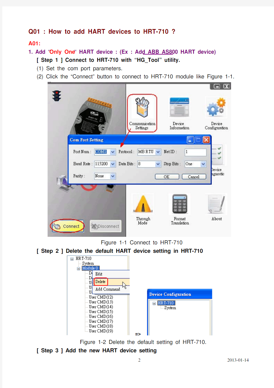
[ Step 1 ] Connect to HRT-710 with “HG_Tool” utility.
(1) Set the com port parameters.
(2) Click the “Connect” button to connect to HRT-710 module like Figure 1-1.
Figure 1-1 Connect to HRT-710
[ Step 2 ] Delete the default HART device setting in HRT-710
=>
Figure 1-2 Delete the default setting of HRT-710.
[ Step 3 ] Add the new HART device setting
(1) Method 1 => Choose “Auto Configure” option to be Enable like Figure 1-3.
Figure 1-3 Add new HART device setting (Auto Config : Enable)
(2) Method 2 => Choose “Auto Configure” option to be Disable like Figure 1-4.
Figure 1-4 Add new HART device setting (Auto Config : Disable) [ Step 4 ] Save the HART device setting to HRT-710
(1) Click the ”Save to Device” button to save the new HART device setting to HRT-710
like Figure 1-5.
Figure 1-5 “Save to Device” function
2. Add “More than One“ HART devices : (Ex : Add ABB AS800 (Addr=2) and Foxboro I/A Pressure (Addr=1) HART devices)
[ Step 1 ] Connect to HRT-710 with “HG_Tool” utility.
[ Step 2 ] Delete the default HART device setting in HRT-710
=> These above two steps are the same with those of the “Only One“ HART device.
[ Step 3 ] Add two new HART device setting
(1) Click “Auto Configure” option to be Disable like Figure 1-6.
Figure 1-6 Add new HART device setting
[ Step 4 ] Save the HART device setting to HRT-710
(1) Click the ”Save to Device” button to save the new HART device setting to HRT-710 like Figure 1-7.
Figure 1-7 “Save to Device” function
Q02 : How to make sure that HRT-710 gets the HART device data correctly ?
A02:
After adding HART device setting to HRT-710 module (refer to the steps of Q01), please follow the steps.
(1) Make sure connecting to HRT-710 with HG_Tool successfully and then click “Device Information” button like Figure 2-1.
Figure 2-1 “Device Information” screen
[ Check I/O Data of the Default CMD(0) ]
(2) Right click the button of mouse on the “Default CMD(0)” item and choose the “Basic operation” option to open the “I/O Data” screen of the “Default CMD(0)” like Figure 2-2.
Figure 2-2 The “Basic operation” of the “Default CMD(0)”
(3) The I/O Data of the “Default CMD(0)” is OK like Figure 2-3.
Figure 2-3 The I/O Data screen of the “Default CMD(0)” => OK
(4) The I/O Data of the “Default CMD(0)” is NG like Figure 2-4.
Figure 2-4 The I/O Data screen of the “Default CMD(0)” => NG
[ Check I/O Data of the Default CMD(3) ]
(5) Right click the button of mouse on the “Default CMD(3)” item and choose the “Basic operation” option to open the “I/O Data” screen of the “Default CMD(3)” like Figure 2-5.
Figure 2-5 The “Basic operation” of the “Default CMD(3)”
(6) The I/O Data of the “Default CMD(3)” is OK like Figure 2-6.
Figure 2-6 The I/O Data screen of the “Default CMD(3)” => OK
(7) The I/O Data of the “Default CMD(3)” is NG like Figure 2-7.
Figure 2-7 The I/O Data screen of the “Default CMD(3)” => NG
=> If the I/O data of the “Default CMD(0)” and “Default CMD(3)” is ok, it means that the communication between HRT-710 and HART devices is ok.
Q03 : How to map HART device CMD(3) data directly to SCADA or HMI ?
A03:
(1) Make sure that the communication between HRT-710 and HART device is ok. (Refer to the steps of Q02)
(2) Set “Swap Mode” of system setting in HRT-710 to be “W&B”.
[1] In “Device Configuration” screen, right click the button of mouse on “System” item and click the “Edit” option to open “System Edit” screen like Figure 3-1.
Figure 3-1 Open “System Edit” screen
[2] Set the “Swap mode” item to be “W&B” and click “OK” button like Figure 3-2.
Figure 3-2 Set “Swap mode” to be “W&B”
[3] Click the ”Save to Device” button to save the new system setting to HRT-710 like Figure 3-3.
Figure 3-3 “Save to Device” function
(3) Check the firmware version of HRT-710 like Figure 3-4.
Figure 3-4 Firmware Version of HRT-710
(4) Follow the below steps according to the different firmware version of HRT-710.
[ 4.1 - The firmware version of HRT-710 is v1.5 or newer ]
[1] In firmware v1.5 or newer, HRT-710 provides the MB Address 1300 ~ 1459 (Default
CMD(3)(S) Data for Module 0 ~ 15 in HRT-710=> The detailed information refers to the sector 4.3 of users’ manual) and users can map the CMD(3) data of HART
device to SCADA directly with these Modbus address 1300 ~ 1459.
[2] For the “Default CMD(3)(S) data of Module 0” in HRT-710, the mapped MB address
is 1300 ~ 1309. The below MB/RTU client will use the “Modbus Poll” tool to show the CMD(3) data of HART device by polling Modbus address 1300 ~ 1309.
<1> Confirm the connection between HG_Tool and HRT-710 is disconnected.
<2> Set the “Modbus” parameters like Figure 3-5.
Figure 3-5 Modbus Parameters of “Modbus Poll” tool
<3> Set the “Display” mode to be “Float” format like Figure 3-6.
Figure 3-6 “Float” format of “Modbus Poll” tool
<4> Set the “Com Port” parameters and click “OK” button to connect to HRT-710
like Figure 3-7.
Figure 3-7 Com Port Parameters of “Modbus Poll” tool
<5> The CMD(3) data of HART device is shown like Figure 3-8.
Figure 3-8 The CMD(3) data of HART device
[ 4.2 - The firmware version of HRT-710 is older than v1.5 ]
[1] Add “User CMD(3)” with “Simple” format and then click “Save to Device” to save the new HART device setting to HRT-710 like Figure 3-9. The mapped Modbus start address and length of User CMD(3) data can be found in “Cmd In address” and “Cmd In size” field. In the example, they are 0 and 20.
Figure 3-9 Add “User CMD(3)” to HRT-710
[2] The below MB/RTU client will use the “Modbus Poll” tool to show the CMD(3) data
of HART device by polling Modbus address 0 ~ 9.
<1> Confirm the connection between HG_Tool and HRT-710 is disconnected.
<2> Set the “Modbus” parameters like Figure 3-10.
Figure 3-10 Modbus Parameters of “Modbus Poll” tool
<3> Set the “Display” mode to be “Float” format like Figure 3-11.
Figure 3-11 “Float” format of “Modbus Poll” tool
<4> Set the “Com Port” parameters and click “OK” button to connect to HRT-710
like Figure 3-12.
Figure 3-12 Com Port Parameters of “Modbus Poll” tool <5> The CMD(3) data of HART device is shown like Figure 3-13.
Figure 3-13 The CMD(3) data of HART device [ Note ]
1. The simple CMD(3) data format and value are shown as below.
[ Index ] [ Format ] [ Description ]
Byte 00~03: float Primary Variable Current
Byte 04~07:float Primary Variable
Byte 08~11: float Secondary Variable
Byte 12~15:float Tertiary Variable
Byte 16~19: float 4th Variable
The 30001 and 30002 registers mean “Primary Variable Current (20.124636)”
The 30003 and 30004 registers mean “Primary Variable (0.385210)”
The 30005 and 30006 registers mean “Secondary Variable (23.494614)”
The 30007 and 30008 registers mean “Tertiary Variable (100.778976)”
The 30009 and 30010 registers mean “4th Variable (0)”
Q04 : How to update the firmware of HRT-710 ?
A04:
[ For HRT-710 hardware v1.1 or firmware v1.1 or below ]
The firmware update function is not supported for users and please contact your local dealer.
[ For HRT-710 hardware v1.2 and firmware v1.2 or newer ]
The firmware update function is supported for users. Please follow the below steps. (1) Download the newest firmware of HRT-710. (Download from
ftp://https://www.doczj.com/doc/bb3047182.html,/pub/cd/fieldbus_cd/hart/gateway/hrt-710/firmware/ )
(2) Turn off the power and open the shell of HRT-710. Then connect the pin 2 & 3 of JP5 together like Figure 4-1.
Figure 4-1 Connect pin 2 & 3 of JP5 together
(3) Connect RS-232 cable between PC and HRT-710 and turn on the power of HRT-710 (LED 1,2,3 will flash every second => Firmware Update Mode) like Figure 4-2.
Figure 4-2 RS-232 Connection between PC and HRT-710 (4) Run “FW_Update_Tool” like Figure 4-3 (Download from :
ftp://https://www.doczj.com/doc/bb3047182.html,/pub/cd/fieldbus_cd/hart/gateway/utilities/fw_tool/ ).
[1] Choose “COM” option and select “Com Port number”.
[2] Click “Browser” button to choose the firmware of HRT-710.
[3] Click “Firmware Update” button to start firmware update process.
[4] Wait for "Firmware Update Success" message.
Figure 4-3 “FW_Update_Tool”
(5) Turn off the power and connect the pin 1 & 2 of JP5 together like Figure 4-4.
Figure 4-4 Connect pin 1 & 2 of JP5 together
(6) Close the shell and turn on the power of HRT-710. Then users can check the firmware version of HRT-710 by using “HG_Tool” like Figure 4-5.
Figure 4-5 Firmware Version of HRT-710
Q05 : How to read HART device command 1 data with standard format by Modbus ?
A05:
(1) By using “HG_Tool” to add “User CMD(1)” of HART device and save settings to
HRT-710. The Modbus start address and length of the “User CMD(1)” will show in the “Cmd In address” and “Cmd In size” field like Figure 5-1. In the example they are 0 and 7 (byte count=7 => word count=4).
Figure 5-1 Add “User CMD(1)” of HART device to HRT-710
(2) The below demo will use the free MB/RTU tool provided by ICP DAS to show HART command 1 data. (Download from
https://www.doczj.com/doc/bb3047182.html,/pub/cd/8000cd/napdos/modbus/modbus_utility/)
(3) Run “MB/RTU” tool. Set the com port settings the same with HART-710 (Baud Rate / Data Bits / Stop Bits / Parity) and then click “Open” button to connect to HRT-710 like Figure 5-2.
(4) Input “1 4 0 0 0 4” in “Command” field and click ”Send Command” button to send the modbus command. The HART command 1 data will be received in “Responses” field => “01 04 08 00 00 3E 0C 20 C5 00 A4 2A 94” like Figure 5-2.
Send Modbus Command :01 04 00 00 00 04 F1 C9
Get Response :01 04 08 00 00 3E 0C 20 C5 00 A4 2A 94