汽车式起重机液压系统
—技术现状与发展趋势
一、行业背景
(一)国外工程汽车起重机的发展趋势
近20年世界工程起重机行业发生了很大变化。RT(越野轮胎起重机)和AT(全地面起重机)产品的迅速发展,打破了原有产品与市场格局,在经济发展及市场激烈竞争冲击下,导致世界市场进一步趋向一体化。为与RT和AT产品抗衡,汽车起重机新技术、新产品也在不断发展。近年来汽车起重机在英、美等国市场的复兴,使人们对汽车起重机产生新的认识。几年前某些工业界人士曾预测,RT 和AT产品的兴起将导致汽车起重机的衰退。日本汽车起重机在世界各地日益流行,以及最近格鲁夫、特雷克斯、林克.贝尔特、德马泰克等公司汽车起重机的产品进展,已向上述观念提出挑战。随着工程起重机各机种间技术的相互渗透与竞争,汽车起重机会在世界市场中继续占有一席之地。
国外工程起重机从整体情况分析,领先国内10~20年(不同类型产品有所不同)。随着国外经济发展速度趋于平稳,工程起重机向智能、高性能、灵活、适应性强、多功能方向发展。25t以下基本上不生产,产品向高附加值、大吨位发展,住友建机、多田野和加藤公司曾于1989年相继推出360t汽车起重机。住友建机在90年代开发出80t~250t共4种AT产品。多田野也在90年代相继推出100t~550t共6种特大型AT产品。加藤公司则研制成NK5000型500t汽车起重机。行业配套也与国内有所不同:
1、下车主要是300kW以上柴油大功率发动机,与之配套的液力变矩器和自动换档变速箱、12吨级驱动转向桥及越野轮胎。
2、上车:高强度材料、大扭矩的起升机构、回转机构、回转支承。
3、液压系统:变量泵、变量马达、电磁换向先导阀及主阀、平衡阀、悬挂系统阀、液压锁、液压缸及管路标准配套件。
4、智能控制系统:力限器显示控制、记忆通讯及单缸顺序伸缩自动控制。(二)国内工程汽车起重机的发展趋势
国内工程机械产品近十年来随着技术的引进、消化、吸收,有了长足的进步,产品性能、可靠性、外观都有较大幅度的提高,但同国外工程机械比较来看,还存在较大差距。
国内工程起重机行业在94~99年是发展低谷,5年中行业几个主要的生产厂家,苦练内功,积极组织产品变型和换代,在产品外观上下功夫。从99年以来,随经济建设新一轮启动,工程起重机市场竞争格局发生巨大变化,各企业不断调整思路、更新观念、转换机制、提高核心竞争力,努力开发产品,开拓市场。产品重心也从8t、12t向16t、25t、50t中大吨位发展,25t增速最快,产量不断翻新,基本占据主导地位。50t产品由于需求面较广,技术逐渐成熟,也大批量进入市场。20世纪末期国内主要产品系列汽车起重机为8t、12t、16t、20t、25t、35t、50t、65t、80t、l00t、125t。整体技术风格是:
下车有全头和半头两种不同风格,多年来半头车因总体布置的方便性及价格因素一直被广泛采用。但近年来随着物质条件的改善,人们的生活条件和质量提高,操作方便、舒适、可靠逐渐成为用户关注的焦点,中大吨位向全头方向发展。
上车操纵从传统的机械操作向液比例和电液比例方向发展,起重吊臂也从传统的三节向四节、五节方向发展,产品的起重性能和起重高度有了较大提高,产品的外观和可靠性有了较大幅度提高。
加入世贸组织后,虽然国内市场(特别是配套件)受到了较大冲击,但同时也给我们带来新技术的应用,使国内主机和配套件企业更清晰认识到差距,更多地了解国产产品存在的致命问题,迫使国产主机和配套件企业不得不进行技术创新和技术进步。
经过几年的努力,国内起重机厂家取得了巨大进步。被誉为神州第一吊的QY300轮式液压汽车起重机2004年在中联浦沅成功下线。它代表了中国汽车起重机制造的最高水平.填补了我国自主研制生产该类产品的空白,打破了此类产品完全依赖进口的惯例。缩短了我国起重机行业与国外的差距,但差距还很大,很多厂家主要还是靠购买国外的“落后”技术,缺乏自主研发能力。这让国人感到担忧。
二、国内外汽车起重机液压系统新技术
(一)关于汽车起重机液压系统安全问题的诸多研究
1. 代智能超载限制器在汽车起重机中的运用
第三代微电脑超载限制器(XT一Ⅲ型),是具有自主知识产权的国产机电一体化装置。该装置由主机部分和传感器部分组成,微电脑控制,模块化结构。安装调试全部采用按键操作、大屏幕液晶点阵显示,在参数设置及显示上非常简明,不用调整任何电位器,使调试变得简单直观,界面友好。限制器采用了数字和大规模集成电路,减少了故障,增加了抗干扰能力,从而提高了可靠性;当起重机超过额定起重量或超行程时,能自动报警并切断起重机向危险方向运动的回路,但允许其向安全方向动作;系统故障自动检测,结果显示;低功耗(整机功耗小于10W),数字电路全部采用CMOS芯片;黑匣子功能,自动记录超载时间及当时的各工况参数;数据及参数显示全部图形汉字提示,数值准确,直观方便,操作人员一目了然,无需操作人员熟记提示符;密码设定功能,防止参数误设定;通用性好,在不改变主机的情况下,只要修改软件,就能够满足各种类型重机机械的要求;机内存储了多组额定载荷曲线,满足了各种工况无级报警要求;对传感器的“温度漂移”和“零点漂移”可进行自动调节补偿;具有声光报警功能。该技术现已被国内很多起重机厂家用于大型起重机上面,效果良好。
2. 重机负荷传感系统分析
负荷传感系统可分为两大类:泵控负荷传感系统和阀控负荷传感系统,前者必须采用变量泵,后者可用于定量泵。目前我国所引进的日本、德国技术常用的是阀控负荷传感系统。阀控负荷传感系统的原理:
阀控负荷传感系统是由泵、负荷传感控制阀(压力补偿阀)和可变节流口(换向阀阀口)等组成。泵提供的工作油液流经可变节流口后,形成负载压力作用于执行机构。负荷传感控制阀接受负载压力传感信号,通过压力补偿作用保持可变节流口两端压差基本不变,并使系统压力仅高于负载压力一个压差。这样,既使得流过节流口的流量仅与节流口开度面积成正比而与负载大小无关,保证了执行机构
运动速度良好的调节性和稳定性;又减少了系统激流的压力损失,提高了系统效率。负荷传感控制阀作为负荷传感系统的核心元件,有多种结构类型。在加藤、多田野和利勃海尔汽车起重机阀控负荷传感系统中,采用了定差胜流阀式、优先
分流阀式及其组合形式。
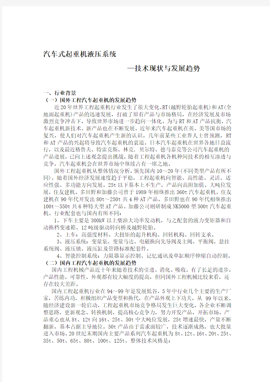
图1负荷传感控制阀压力补偿作用原理
图1为定差溢流阀和优先分流阀的压力补偿作用原理图。如图中所示,当可变节流口(换向阀阀口)FC处于某一开度位置,定差溢流阀及RC或优先分流阀PF 达到平衡状态时,FC两端压差△Pt(Po—Pr或P1—Pr)对阀芯所产生的液压作用力与阀芯左端弹簧力将保持平衡。来自泵的工作油液(Po)一部分直接或经阀口h1去FC支路,另一部分剩余油液经阀口h2去油箱或旁通支路(Pz)。若FC支路负载压力Pr随执行机构负载增加(减小)时,阀芯右移(左移),减小(增大)阀口h2和增大(减小)阀口h1,结果系统压力Po和优先支路压力Pl增加(减小),于是阀芯重新平蘅在一个新的阀口位置处。由于弹簧设计得较弱,且阀芯平衡位置变化的位移量很小,因此弹鳖力的变化可以忽略不计,从而保证与弹簧力相平衡的换向阀节流口FC两端压差将基本上保持不变。同时,系统压力仅略高于负载压力。对定差溢流阀而言,系统压力Po高于负载压力Pr一个定值,即由弹簧设定的换向阀节流口两端压差△Pt对优先分流阀而言,优先支路压力P1=Pr+△Pt;系统压力Po则略高于支路压力P1与P2中的大者。
3. 重机的拘停保护
起重机电动机的控制接触器常常是密集通断的,因此易发生触头熔焊故障。当起重机在运行过程中需要准确定位或紧急停止时,如果因触头熔焊导致起重机拒停,就有可能发生碰撞事故。为解决这个问题,提出一个起重机升降机构拒停保护设计。
从三个方面着手解决这个问题,其一是接触器触头熔焊导致其动作不合逻辑,这可增加一个中间继电器来判断;其二是为避免接触器、继电器动作竞争导致保护误起动,为此拒停保护设置短暂延时,即需要一个时间继电器;第三是一旦接触器拒跳时,由总断路器分励脱扣动作执行保护。
从电气角度看,防止起重机拒停的关键措施是监视制动器接触器触头是否熔焊。图2是QRIS型升降机构控制柜采用拒停保护的设计电路图。
这个设计电路由三个环节构成。第一个是监视环节,由与制动器接触器K07线圈并联的中间继电器构成,K07与K1 正常情况下是同步动作的。如果K7因触头熔焊不能释放,那么两者动作就不一致,这就将起动延时环节。
第二环节,即延时环节是借用原设计中的K03时间继电器,由并联的K7 常闭接点和K07常开接点控制。K7、K07 并联接点在正常情况下总是接通的,只有在停止时K7触头发生熔焊的情况下并联接点才断开。K03时间继电器通电立即吸合,断电延时释放,延时0.6s,因此只要控制电路一得电,K03立即吸合。而且主令控制器S40 。在起动、停止的切换过程中,即使K7、K07 接点动作竞争,瞬时断开线圈回路,K03延时闭合的常闭接点仍保持断开,因此K7、K07 并联接点接入K03线圈回路不会影响K03 的正常工作。
在未接入并联接点前,只有在主令控制器转到上升2挡或下降3挡后,因加速级接触器K42得电,K42常闭接点断开,K03才断电释放,其常闭接点延时闭合,使加速级接触器K41能够吸合,切除第3级起动电阻。在主令控制下降2挡一0挡一上升1挡之间切换时,由于主令控制器17、18和19、20接点均是断开的,加速级接触器K42不能吸合,K03不可能断电,此时常闭接点也不起作用,即K03在升降
机构起动和停止阶段实际上是不工作的。而拒停保护正是工作在起重机停止和起动阶段,因此可以在K03不工作的时间将其借来为拒停保护工作,为此,在K03线圈回路中插入并联接点。一旦因K7触头熔焊导致起重机拒停,并联接点立即断开,K03继电器断电,其常闭接点经0.6s延时后闭合,接通总断路器Q0的分励脱扣线圈YA—OFF,使总断路器跳闸,升降机构制动器断电制动,达到拒停保护的目的。
第三个环节是拒停保护起动环节,它由K03延时闭合的常闭接点、K7常开接点、K07常闭接点与总断路器分励脱扣线圈串联而成。总断路器刚合闸的瞬间,K07的常闭接点尚未断开,为此必须在串联电路中接入K7常开接点,否则将导致分励脱扣线圈得电,使总断路器刚合闸就立即跳闸。K07常闭接点的作用是防止K03在执行原设计的功能,即延时切除第3级起动电阻时,导致总断路器误跳闸。因为在起重机加速阶段,K07常闭接点是断开的,因此分励脱扣线圈不会因K03常闭接点闭合而得电,导致误跳闸。
如果起重机起动前制动接触器K7触头已经熔焊,那么一合上总断路器Q0由于并联接点断开,使K03处于断电状态,K03常闭接点闭合,而此时K7常开接点、K07常闭接点均闭合,这样分励脱扣线圈得电,使刚合上的总断路器立即跳闸,阻止起重机在不能制动的状态下起动,消除了事故隐患。
为检修安全,将原设计中升降机构控制电源的转换开关Q3由二极改为四极,这样Q3断开时,就切断了升降控制电路与总断路器分励脱扣电路的连接,确保升降控制电路完全断电。Q3可以选用HZ5—10型四极组合开关。
因利用了原设计中的时间继电器,起重机升降机构的拒停保护只需要增加一个中间继电器,并将一个二极组合开关改为四极组合开关,所需费用不大。(二) 起重机电子控制技术
为了提高工程起重机作业效率、减轻劳动强度、防止事故、保障人身和设备安全,采用了多种多样的控制装置。操纵与控制已成为起重机的重要问题。
要解决操纵与控制问题,仅靠机械和液压是很不够的,因为操纵与控制实际上是信息处理问题。机械和液压信息处理能力低,控制性能差,必须引进信息处理能力强、控制性能良好的电子技术。现就当前工程起重机上采用得电子控制装置作一一概述。
1. 载荷力矩限制
为了防止由于过大的载荷所引起的倾翻和折臂等事故,在工程起重机上设置了载荷力矩限制器。
微机控制力矩限制器的工作原理如如3所示。它是由吊臂角度,长度,起重量,支腿跨矩等检测装置,微机控制装置,显示,报警及执行机构组成。
其基本工作原理是,由检测装置通过传感器将吊臂的长度,角度,支腿跨矩等信号,送如微机控制装置。微机控制装置计算出在当前的情况下,起重机允许起吊的最大重量,与传感器测出的起重机实际起吊重量进行比较,如果实际起吊重量达到允许起吊重量的90%,则微机系统通过显示器和蜂音器发出预报警,提醒操作人员小心操作。当比值达到100%时,微机系统通过显示器和蜂音器指示作业人员停止当前作业并通过执行机构限制起重机只能进行安全方向操作,停止一切危险方向的操作。
图3 微机控制力矩限制器原理简图
2. 反力感知系统
起重作业时,作业人员用眼睛往往不能正确估计吊重的重量,特别目前采用先导液压操纵,减轻了操纵力在操纵时荷重的变化,载荷的起吊下落等情况,司机没有手感,在进行建筑构件吊装和机器设备安装时感到操纵困难。为此,在有些起重机采用了电子感知系统。
装置了反力感知系统后,由于有负荷力反馈,司机在操纵杆上可感知吊重的大小,有助于高精度微动操纵。同时可避免由于起吊过猛,吊重摆动等原因引起的人身和设备事故。
基本工作原理是检出卷扬马达的压力,通过控制器发出控制电信号,控制电液比例阀产生相应的液压,作用于反力活塞上,使操纵杆上产生负荷反力感觉。
反力感知系统可以通过反力设定装置,根据司机的个人特点和作业类型来设定反力的大小,当认为不需要时,还可以将反力感知系统解除。
3. 防碰撞控制
工程起重机在狭窄的场地工作时,需要控制其作业范围,即限制起重机的旋转及度及动臂伸缩和变幅范围。
常采用示教再先方式来进行控制,先由操作人员按允许工作范围操作一遍,由危机系统记下其轨迹,通过此方式设定作业范围。也可用超声波障碍物检测装置来实现房碰撞控制。
为了防止碰撞高压线,引起触电事故和造成供电故障,采用接近高压线自动报警装置,
检测装置一般采用球形电极,通过静电感应,检测电网的电声强度,然后将微弱信号经前置放大后,通过灵敏度装换处理得出与电网的距离,再与控制基准比较,输出相应的控制信号。
4. 吊重控制装置
在高层建筑和高架道路的建设工程中,为了提高作业效率,缩短工期,使操作简便和提高安全性,常采用以下吊重控制装置——自动水平移动控制装置。
在起重作业中往往需要吊重作水平移动,通常是靠司机操作技术来实现的,司机目视吊重的高度,同时操纵变幅和起升两个手柄,又要观察注意周围情况,操作难度相当大。采用自动水平移动控制装置,只需操纵动臂变幅一个操纵杆,就能平稳、迅速作高精度的水平移动。
自动水平移动控制装置的组成所示。由传感器,操纵装置控制微机和电液变换执行装置等组成。传感器包括:角度检测器检出住臂或副臂的角度;旋转编码器检测住卷筒或副卷筒的转动量;压力检测器检出住臂变幅操纵阀的先导操纵压力,作为前反馈输入控制微机;发动机转速传感器检出发动机转速,根据发动机转速来改变系统的增益。由主臂角度可算出主臂上支点的高度,为保持吊重水平移动可算出起升卷筒所需的转动量,来控制卷筒的转动,与旋转编码器测得的卷筒实际转动量作比较进行修正。压力前反馈和根据发动机转速来改变曾益的目的,是为了得到高精度平稳的水平移动。此装置采用手动优先原则,主要起升卷筒一操纵,就自动地从自动切换至手动,当突然遇到障碍物时可避开。
图9 自动水平移动控制装置组成
另外为了防止起吊时侧位,产生吊重摇摆而引起翻车、碰撞和折臂等事故,
采用吊重中心追随控制机构,如图10a所示,只要按一下卷筒操纵杆的按钮,就能实现吊重中心自动追随。还有旋转急停和旋转缓停转换控制装置。
图10 吊重中心追随和旋转控制机构
5. 多路信号传送装置
在单司机室的越野起重机上,一个技术上困难问题是如何在有相对运动的上下之间传递大量的操纵控制信息(多达几十个)。驾驶室在上车,而发动机,变速器,转向,制动和支腿等在下车,如何操纵和来控制它们,解决的办法是尽量将液压控制信号改为电控制信号,同时为了减少通路,希望一条通路传递多路信号,这就需要利用微机电子技术。
除了上述介绍的电子控制装置以外,还有许多控制装置。
在发动机,泵和阀的控制方面:需要适应负载变化和多个液压作动器同时动作复合操作时的功率控制,实现高载低速和减轻高速,与发动机功率相匹配,充分发挥发动机功率;微机操作时发动机和泵的控制,与负载无关和同时动作十相互无干扰,仅取决于手柄操纵的速度控制,以改善其操纵性能;带负载感应补偿的节能控制,降低燃
料消耗量。目前这些
方面还大量采用液压控制,可以预计不久将来将被控制性能优越的电子控制所取代。另外。这些控制系统目前大多是发动机,泵和阀分开单独控制,今后预计将实现联合控制。
在全路面起重机和越野起重机上,目前已有不少采用了微机控制自动换档变速器。
另外,还有电子监视和故障自动诊断装置等。总之,可以说操纵与控制,起重机内的信息处理已成为当前起重机进一步发展的焦点。虽然目前电子控制尚存在不少为体,例如传感器技术和电液转换技术收纳感不够成熟,微机控制系统的抗干扰,包括电磁辐射干扰,温度,湿度,振动和冲击等引起的环境干扰,确实电子控制的可能性尚存一定问题,但是电子控制是不抗拒的技术潮流,机电信一体化是工程机械产品更新换代的必然发展方向。
三、展望未来
目前起重机的控制系统主要是机械液压控制,随着电液比例控制技术和电子技术在控制系统中的比重越来越大以及它的优越性,电液控制将是主要发展潮流。随着液压元件、微机技术和信息技术的不断发展,智能液压起重机即将出现。那时这种“巨人”可以替代人们做更多的繁重工作,为人类的发展起到无法估计的作用。
Truck crane hydraulic system
Technical status and development trend of
One, industry background
( a ) the development trend of foreign engineering truck crane
The past 20 years the world's construction crane industry produced very big change. RT ( cross-country wheel crane ) and AT ( all terrain crane ) the rapid development of product, broke original products and the pattern of the market, in the economic development and the fierce competition in the market impact, leading to world market further towards integration. As with RT and AT counter products, automobile crane new technology, new products are also constantly developing. In recent years auto crane in Britain, the United States market revival, enabling people to generate new understanding of automobile crane. A few years ago, some industry had predicted, the RT and AT product rise will lead to automobile crane recession. Japan automobile crane is increasingly prevalent throughout the world, and more recently, grove, Terex, Linc. Belt, Tokuma Yasuke and other companies automobile crane product development, has the idea to challenge. With all types of engineering crane technology mutual infiltration and competition, automobile lifting the opportunity to continue to occupy a space for one person in the world market.
Foreign crane from the overall situation, the leading domestic 10~20 years ( different types of different products ). Along with the economic development speed smoothly, construction crane to the intelligent, high-performance, flexible, adaptable, multi-functional direction. The following 25t basically is production, products to the high value added, large tonnage, Sumitomo Construction machinery, the Tadahino and Kato company in 1989 has introduced 360t truck crane. Sumitomo Construction Machinery in the 90's the development of 80t~250t total of 4 kinds of AT products. TADANO also in 90 time in succession to launch 100t~550t total of 6 kinds of large AT product. Kato company developed NK5000 type 500t truck crane. Supporting industries and domestic different:
1, get off the main diesel engine power is more than 300kW, and the matching of torque converter and automatic gearbox, 12 tons of drive steering bridge and off-road tires. In 2,: high strength material, large torque of the lifting mechanism, a rotating mechanism, slewing bearing. 3, hydraulic system: variable pump, a variable motor, an electromagnetic reversing valve and main valve, balance valve, suspension system, hydraulic lock valve, hydraulic cylinder and standard pipe fittings. 4, intelligent control system: limiter display control, memory communication and single cylinder sequential telescopic automatic control.
( two) the development trend of domestic engineering truck crane
Domestic engineering machinery products for nearly ten years with the technology introduction, digestion, absorption, had great progress, product performance, reliability, appearance has greatly improved, but compared with the foreign engineering machinery, still put in bigger difference.
China engineering crane industry in 94 ~99 years is the development of the trough, 5 years in the industry several major manufacturers, bitter Liannei Gong, active organization variant and
replacement, in product appearance. From 99 years since, with economy construction is new round started, construction crane market competition pattern produces tremendous change, the enterprise constantly adjust train of thought, newer idea, changeover mechanism, enhance core competitiveness, product development efforts, to develop the market. Product focus from 8t to 16t, 12t, 25t, 50t 25t large tonnage development, the fastest growth rate, yield is renovated ceaselessly, basic dominant. 50t products due to the requirement of wide, technology mature gradually, also enter the market in large quantities. The end of the twentieth Century domestic main products automobile crane for the 8t, 12t, 16t, 20t, 25t, 35t, 50t, 65t, 80t, l00t, 125t. The overall style is: Get off with the head and half head two different styles, for many years a half head car because of overall layout of convenience and price factors have been widely adopted. But in recent years with the improvement of material conditions, people's living conditions and quality improvement, convenient operation, comfortable, reliable users gradually become a focus, large and medium tonnage to the head direction.
The car is manipulated from the traditional mechanical operation to the hydraulic and electro-hydraulic proportional direction, lifting arm from the traditional three section to the four section, five section of the direction of development, product lifting performance and lifting height has been greatly improved, product appearance and reliability are greatly improved.
After joining WTO, while the domestic market ( especially with Kit ) got bigger impact, but also bring us new technology applications, so that domestic host and supporting enterprise more clearly recognize the gap, to learn more about the domestic products are fatal problems, forcing domestic host and supporting enterprises to carry on technological innovation and technical progress.
After several years of efforts, the domestic crane manufacturers have made great progress. Known as China the first hanging QY300 wheeled hydraulic truck cranes Puyuan success off the assembly line in 2004 in. It represents the Chinese automobile crane manufacturing at the highest level. To fill China's independent research and production of the product blank, broke this kind of product entirely dependent on imports of the convention. China's crane industry to shorten the gap with foreign countries, but the gap is still very great, a lot of manufacturers mainly rely on the purchase of foreign "backward " technology, lack of independent research and development ability. It makes people feel worried.
Two, domestic and foreign automobile crane hydraulic system new technology
( a ) on truck crane hydraulic system security problems research
The 1 generation of intelligent overload limiter of crane in automobile application
The third generation of microcomputer overload limiter ( XTⅢ), with independent intellectual property rights of domestic electromechanical integration device. The device is composed of a main machine part and a sensor part, microcomputer control, modular structure. Installation and commissioning of all the key operation, large screen LCD dot matrix display, in the setting of parameters and the display is very concise, do not adjust any potentiometer, the debugging is simple and intuitive, friendly interface. Limiter adopts digital and large scale integrated circuit, reducing the failure, increases the capacity of resisting disturbance, thereby improving reliability; when the crane is more than the rated capacity or stroke, can automatically alarm and cut off the crane to the dangerous movement of the loop, but allows it to move towards a safe direction; system of automatic fault detection, the results showed; low power ( power consumption less than 10W), digital circuit using all the CMOS chip; a black box function, automatic recording overload
time and then the operational parameters; data and parameters of all Chinese characters display graphics presentation, numerical accuracy, convenient operation, stick out a mile, no operator is required to memorize the password prompt; setting function, prevent parameter error setting; good generality, without altering the host circumstances, as long as the software changes, can meet various types of heavy machinery; machine memory a plurality of rated load curve, satisfy various working continuously alarm calls; the sensor " drift " and " drift " can carry out automatic regulation and compensation with sound and light alarm function. The technique has been used in many domestic manufacturers of large crane crane above, good results.
2 heavy machine load sensing system analysis
Load sensing system can be divided into two categories: pump control load sensing system and valve control load sensing system, the former must use of variable pump, the latter can be used for quantitative pump. At present our country by the introduction of Japan, Germany technology used is the valve load sensing system. Valve load sensing system principle:
Valve load sensing system is composed of a pump, load sensing control valve ( valve ) and settable orifice ( valve port of the valve ). Pump to provide the oil flowing through the settable orifice, to form the load pressure is applied to the actuator. Load sensing control valve for receiving a load pressure sensor signal, through the pressure compensation function of settable orifice pressure difference between the ends basically unchanged, and the system pressure just above the load pressure of a pressure differential. Thus, both the flow through the orifice flow only with the throttle opening is proportional to the area and are independent of load, guarantees the implementation of mechanism motion speed regulation and good stability; and reduce the system stream pressure loss, improves the efficiency of the system. Load sensing control valve as the load sensing system core components, has many kinds of structure types. In Kato, Tadahino and Liebherr crane control valve load sensing system, employs a constant difference wins flow valve type, the priority valve type and its combination form.
Fig 1 load sensing control valve pressure compensation principle
The constant difference overflow valve and the priority valve pressure compensation principle diagram. As shown in the picture, when settable orifice ( valve valve ) FC in an open position, the constant difference overflow valve and RC or the priority valve PF balance, FC pressure difference between the ends of△ Pt ( Po, Pr or P1 - Pr ) on the valve plug produced by the hydraulic force and valve spring force will keep balance. From the pump working fluid ( Po ) part directly or through the valve port H1 to FC branch, another part of the remaining oil through the valve port H2 to tank or by-pass ( Pz ). If the FC branch load pressure of Pr with the actuator load increases ( decreases ), the valve core is shifted to the right ( left ), decrease (increase ) the valve opening H2 and increase (decrease) the valve opening H1, the results of system pressure Po and preferred branch pressure Pl increases ( decreases ), then the valve core to balance in a new valve export position. Because the spring design is weaker, and the valve core balance position displacement amount is very small, thus playing the turtle force changes are negligible, thus ensuring and spring force balance valve throttle pressure difference across the FC will basically remain unchanged. At the same time, the system pressure is only slightly higher than the load pressure. On the constant difference overflow valve, pressure Po above the load pressure Pr a constant value, namely the spring set valve throttle pressure difference between the ends of the priority valve of △ Pt,△ Pt priority branch pressure P1=Pr+; Po system pressure slightly higher than the pressure of P1 and P2 branch of the larger.
3 heavy machine limited stop protection
Crane motor control contactors are often dense on-off, therefore prone to breakdown. When the crane is in the process of operation required for accurate localization or emergency stop, because if the contact welding leads the crane refused to stop, there may be a collision accident. In order to solve this problem, propose a crane lifting mechanism refused to stop protection design.
From three aspects to solve this problem, it is a contactor contact welding leads to the action logic, which can increase a middle relay to judge; second is to avoid the contactor, relay competition leads to protection false start, therefore refused to stop protection setting short delay, which requires a time relay; third is once contactor refused to jump, by the general circuit breaker shunt tripping action execution protection.
From the perspective of crane electrical, prevent to stop are key measures to monitor whether the brake contactor contact welding. QRIS type lifting mechanism control cabinet adopts non stop protection circuit diagram design.
The design of circuit is composed of three parts. The first is to monitor, made with brake contactor K07 coil is connected in parallel with the intermediate relay, K07 and K1 under normal circumstances is the synchronization action. If the K7 due to contact welding cannot release, so both movement is inconsistent, it will start delay time link.
Second links, namely time delay is borrowed from the original design in the K03 time relay, consists of parallel K7 normally closed contact and a normally open contact of the control K07. K7, K07 parallel contact under normal conditions is always connected, stopping only when the K7 contact occurs when welding condition and connection to disconnect. K03 time relay is energized immediately attracted, power-off time delay time delay release, 0.6s, so long as the control circuit on electric, K03 immediately. And the main controller S40. At the start, stop switch process, even though the K7, K07 contact action of competition, instantaneous disconnection coil circuit, K03 time delay closing of the normally closed contact remained disconnected, so K7, K07 parallel contact access K03 coil loop does not influence the normal work of K03.
In an access of parallel contacts before, only in the main controller to rise or fall 3 Block 2 block, due to acceleration level contactor K42 electric, K42 normally closed contacts open, K03 power release, the normally closed contact of the time delay closing, accelerating stage contactor K41 can attract, resection of third level dynamic resistance. In the master control down 2 blocks a block 0, a rise of 1 block when switching between the master controller, 17, 18 and 19, 20 contacts are disconnected, accelerating stage contactor K42 cannot attract, K03 may not power off, the normally closed contact also does not work, namely K03 in lifting mechanism for starting and stopping phase is actually not working. And refused to stop protection is working in crane stopping and starting stage, so can be used in K03 does not work all the time be borrowed for refusing to stop protection work, therefore, in the K03 loop of the coil is inserted in the parallel contacts. Once the K7 contact welding leads the crane refused to stop, parallel contact immediately disconnect, the K03 relay is de-energized, the normally closed contact of the 0.6s delay after the closure, connect to the main circuit breaker Q0 shunt trip coil YA - OFF, bringing the total tripping the circuit breaker, lift brake power-off brake, achieve the purpose of non stop protection.
The third link is non stop protection starting point, which consists of a K03 time delay closing of the normally closed contact of the normally open contact, K7, K07 normally closed contact with the total circuit breaker shunt trip coil connected in series. Main breaker just closing
moment, K07 normally closed contact has not yet been disconnected, so we must in the series circuit access K7 normally open contact, otherwise it will cause shunt trip coil gets electricity, making the total circuit breaker tripping just closing immediately. K07 normally closed contact role is to prevent the K03 in the execution of the original design features, i.e. delayed resection third starting resistance, resulting in a total circuit breaker tripping. Because of the crane is accelerated stage, K07 normally closed contact is disconnected, so the shunt trip coil K03 will normally closed contacts closed and electricity, resulting in incorrect trip.
If the crane braking contactor before starting K7 contact is welded, so a total circuit breaker Q0 because the shunt contact is opened, so that the K03 is in an off state, K03 normally closed contacts closed, normally open contact, while the K7 K07 normally-closed contacts are closed, so the shunt trip coil gets electricity, so just close general circuit breaker tripping prevent crane in immediately, not braking condition start, eliminate accident hidden danger.
For the maintenance of safety, the original design of lifting mechanism control power conversion switch Q3 by diode instead of quadrupole, so Q3 disconnected, cut off the lifting control circuit and circuit breaker shunt tripping circuit connection, ensure the lifting control circuit power. Q3 can use HZ5 - 10 type quadrupole combined switch.
By the use of the original design of the time relay, crane lifting mechanism of non stop protection only needs to add an intermediate relay, and a diode switch to quadruple combination switch, costs less.
( two) crane electronic control technology
In order to improve the construction crane operation efficiency, reduce labor intensity, prevent accidents, ensure the personal and equipment safety, using a variety of control device. Manipulation and control has become the important problem of crane.
To solve the problem by manipulation and control, machinery and hydraulic pressure is not enough, because the steering and control is actually the problem of information processing. Mechanical and hydraulic information processing capacity is low, the control performance is poor, must introduce information processing capability, good control performance of the electronic technology. The current engineering crane electronic control device used for one one overview.
1 load torque limit
In order to prevent the excessive loads caused by the tilting and the folding arm and other accidents, the construction crane is arranged on the load moment limiter.
Microcomputer control of torque limiter principle as shown on the 3. It is composed of a suspension arm angle, length, weight, leg span detection device, microcomputer control device, display, alarm and executive mechanism.
The basic working principle, composed of a detection device by a sensor arm length, angle, legs cross torque signal, sent as a microcomputer control device. Microcomputer control device calculates in the current circumstances, the maximum weight allowed hoisting crane, and the crane hoisting weight sensor detects the actual comparison, if the actual lifting weight to allow lifting weights 90%, then the computer system by a display and a buzzer sends out the alarm, to remind operators of careful operation. When the ratio reached 100%, a microcomputer system by a display and a buzzer to instruct operators to stop the current task and by performing a mechanism to restrict the crane only safe operation direction, stop all the dangerous operation.
Fig 3 Schematic diagram of microcomputer control torque limiter
The 2 force sensing system
Hoisting operation, operation personnel eyes often can not be correctly estimated lifting weight, especially the pilot hydraulic control, reduces the operating force in operation when load changes, load lifting falling situation, drivers do not feel, in building structure hoisting and installation of machinery equipment was operating difficulties. Therefore, in some crane adopts electronic sensing system.
Device a force sensing system, due to a negative force feedback, the driver on the control lever can be perceived hanging weight size, contribute to the high precision micro manipulation. At the same time can be avoided due to excessive lifting, hoisting swing and other causes of person and equipment accident.
The basic principle is to detect the hoisting motor pressure, through the controller sends the control signals, to control the electro-hydraulic proportional valve to produce the corresponding hydraulic, acting on the reverse force on the piston, allowing manipulation of rod produces the load force feeling.
The force sensing system can be achieved by reverse power setting device, according to a driver's personal characteristics and job types to set the counter force, when think that do not need, also can be opposite force sensing system for lifting.
3 anti collision control
Construction crane in narrow site work, need to control its operation range, namely limit crane rotation and degree and a movable arm telescopic and variable range.
Often used to teach again means to control, the operating personnel according to the allowable working range operation again, the crisis system down its trajectory, the way of setting the scope of work. Also available ultrasonic obstacle detection device to realize real collision control.
In order to prevent collision high-pressure line, cause electric shock caused by accidents and power supply failure, with close to the high voltage line automatic alarm device,
Detection device usually adopts spherical electrode, through electrostatic induction, detection grid acoustic intensity, then the weak signal preamplifier, through the sensitivity equipment for processing and gets the power distance, and the control baseline comparison, the output of the corresponding control signal.
4 lifting control device
In high-rise building and the viaduct 's construction, in order to improve the working efficiency, shorten time limit for a project, so that the operation is simple and improves the safety, often using the following lifting control device of automatic level -- mobile control device.
In the lifting operation is often required in every level of mobile crane, usually by the driver operating the technology, driver visual hoisting height, while manipulating the amplitude and lifting the two handles, and observed around, operation difficulty is quite big. Automatic level control device using mobile, simply manipulation of luffing jib of a joystick, can be stable, rapid high precision horizontal movement.
Automatic level control device consisting of the mobile. Composed of sensors, control device and control microcomputer electro-hydraulic conversion execution device. The sensor includes : a detection arm angle detector for or jib angle; rotary encoder testing live drum or side drum rotation quantity; pressure detector detection for arm control valve pilot control pressure, as a feedback input control microcomputer; engine speed sensor detection engine speed, according to the engine speed to vary the gain of the system. From the main arm angle can be calculated on the main arm pivot point height, in order to maintain the level of mobile crane hoisting drum can
calculate the required amount of rotation, to control the rotation of a spool, and a rotary encoder is measured by the actual amount of rotation reel comparison is made with modified. Pressure feedback and according to the engine speed to change had beneficial purposes, in order to get a high accuracy stable level mobile. The device adopts manual priority principle, main hoisting drum manipulation, automatically switching from automatic to manual, when suddenly encountered an obstacle avoiding.
Figure 9 automatic horizontal movement control device.
In addition to prevent lifting of side, produces a lifting swing caused by collision and rollover, arm folding and other accidents, the hoisting center follow control mechanism, as shown in Figure 10a, just click reel joystick button, can achieve hoisting center automatic following. There are rotating emergency-stopping and rotary suspension conversion control device.
Fig 10 hoisting center follow and rotation control mechanism
5 multiplex signal transmission device
In the single cab off-road crane, a technically difficult problems is how the relative motion between upper and lower transmitting large amount of control information ( up to several dozen ). Cab in the car, and the engine, transmission, steering, braking and leg in the car, how to manipulate and to control them, the solution is to try to hydraulic control signal to electrical control signals, at the same time in order to reduce pathways, a pathway that transfer the multiplex signal, this would require the use of computer and electronic technology.
In addition to the introduction of the electronic control device, and many control device.
In the engine, pump and valve control : the need for adaptation to load changes and multiple hydraulic actuators which act at the same time composite operation of the power control, achieve high loading speed and reduce the speed, and engine power match, give full play to the engine power; microcomputer operation when the engine and pump control, and is independent of the load and at the same time act ten no mutual interference, depends only on the handle to control speed control, to improve its maneuverability; load sensing compensation energy saving control, reducing the fuel consumption. Currently these also uses lots of hydraulic control, can be expected in the future will be excellent control performance of electronic control is replaced by. In addition. These control systems are mostly engine, pump and valve controlled separately, the future is expected to achieve joint control.
In all terrain crane and cross-country crane, many using the computer controlled automatic transmission.
In addition, there are electronic surveillance and automatic fault diagnosis device. In short, can be said to manipulate and control, crane within the information processing has become the focus of further development of crane. Although there are still a lot of electronic control for the body, for example, the sensor technology and the electrohydraulic conversion technology storage are not mature enough, microcomputer control system, including electromagnetic radiation interference, temperature, humidity, vibration and impact caused by environmental interference, do electronic control probability of surviving a certain problem, but electronic control is not resist technology trends, machine integrated telecommunication engineering machinery product upgrading of the inevitable development direction.
Three, look to the future
The crane control system is mainly mechanical hydraulic control, with electro hydraulic proportional control technology and electronic technology in the control system of the
increasingly large and its superiority, electro-hydraulic control will be the main development trend. With the hydraulic components, computer technology and the continuous development of information technology, intelligent hydraulic crane coming. Then the " giants " can replace people to do more work, for human development to estimate the role.
机械设计 摘要:机器是由机械装置和其它组件组成的。它是一种用来转换或传递能量的装置,例如:发动机、涡轮机、车辆、起重机、印刷机、洗衣机、照相机和摄影机等。许多原则和设计方法不但适用于机器的设计,也适用于非机器的设计。术语中的“机械装置设计”的含义要比“机械设计”的含义更为广泛一些,机械装置设计包括机械设计。在分析运动及设计结构时,要把产品外型以及以后的保养也要考虑在机械设计中。在机械工程领域中,以及其它工程领域中,所有这些都需要机械设备,比如:开关、凸轮、阀门、船舶以及搅拌机等。 关键词:设计流程设计规则机械设计 设计流程 设计开始之前就要想到机器的实际性,现存的机器需要在耐用性、效率、重量、速度,或者成本上得到改善。新的机器必需具有以前机器所能执行的功能。 在设计的初始阶段,应该允许设计人员充分发挥创造性,不要受到任何约束。即使产生了许多不切实际的想法,也会在设计的早期,即在绘制图纸之前被改正掉。只有这样,才不致于阻断创新的思路。通常,还要提出几套设计方案,然后加以比较。很有可能在这个计划最后决定中,使用了某些不在计划之内的一些设想。 一般的当外型特点和组件部分的尺寸特点分析得透彻时,就可以全面的设计和分析。接着还要客观的分析机器性能的优越性,以及它的安全、重量、耐用性,并且竞争力的成本也要考虑在分析结果之内。每一个至关重要的部分要优化它的比例和尺寸,同时也要保持与其它组成部分相协调。 也要选择原材料和处理原材料的方法。通过力学原理来分析和实现这些重要的特性,如那些静态反应的能量和摩擦力的最佳利用,像动力惯性、加速动力和能量;包括弹性材料的强度、应力和刚度等材料的物理特性,以及流体润滑和驱动器的流体力学。设计的过程是重复和合作的过程,无论是正式或非正式的进行,对设计者来说每个阶段都很重要。 最后,以图样为设计的标准,并建立将来的模型。如果它的测试是符合事先要
液压传动 第十讲 制动器 力流体动力系统的优秀的特性之一是由电源产生,通过适当的控制和指导,并通过电线传输,就可以轻松转换到几乎任何类型的机械运动所需要用到的地方。使用一个合适的驱动装置,可以获得线性(直线)或者是旋转运动。驱动器是一种转换流体动力机械力和运动的装置。缸、马达和涡轮机是最常见的将流体动力系统应用于驱动设备的类型。这一章描述了各种类型的动作汽缸和他们的应用程序、不同类型的流体汽车和使用流体动力系统的涡轮机。 汽缸 制动汽缸是一种将流体动力转换成线性或直线、力和运动的装置。因为线性运动是沿着一条直线前后移动的往复运动。这种类型的制动器有时被称为一个往复、或线性、电动机。由ram或活塞组成的汽缸在一个圆柱孔内操作。制动汽缸可以安装,以便汽缸被固定在一个固定的结构,ram或活塞被连接到该机制来操作,或者是活塞和ram可能被固定到固定结构,汽缸附加到机械装置来操作。制动汽缸气动和液压系统的设计和操作是类似的。一些变化的ram和活塞式制动汽缸的内容将在后面的段落中描述。 冲压式缸 术语ram和活塞通常可以互换使用。然而,一个冲压式缸通常被认为是一个截面积活塞杆超过一半的截面积活动元件。在大多数这种类型的制动汽缸中,杆和活动元件各占一半。这种类型的活动元件经常被称为柱塞。冲压式缸主要是用来推动而不是拉。一些应用程序需要ram的一部分在平坦的外部来推动或升降单位操作。其他应用程序需要一些机械装置的附件,如一个U型夹或有眼螺栓。冲压式缸的设计在很多其他方面不同,以满足不同应用程序的要求。 单作用千斤顶 单作用千斤顶(如图:10-1)试用力只在一个方向。流体定向的汽缸取代ram 和他外部的弹性元件,将物体举起放在上面。
外文资料翻译译文 塔式起重机 动臂装在高耸塔身上部的旋转起重机。作业空间大,主要用于房屋建筑施工中物料的垂直和水平输送及建筑构件的安装。由金属结构、工作机构和电气系统三部分组成。金属结构包括塔身、动臂和底座等。工作机构有起升、变幅、回转和行走四部分。电气系统包括电动机、控制器、配电柜、连接线路、信号及照明装置等。 塔式起重机简称塔机,亦称塔吊,起源于西欧。据记载,第一项有关建筑用塔机专利颁发于1900 年。1905 年出现了塔身固定的装有臂架的起重机,1923 年制成了近代塔机的原型样机,同年出现第一台比较完整的近代塔机。1930 年当时德国已开始批量生产塔机,并用于建筑施工。1941 年,有关塔机的德国工业标准DIN8770 公布。该标准规定以吊载(t)和幅度(m)的乘积(tm)一起以重力矩表示塔机的起重能力。 我国的塔机行业于20 世纪50 年代开始起步,相对于中西欧国家由于建筑业疲软造成的塔机业的不景气, 上海波赫驱动系统有限公司我国的塔机业正处于一个迅速的发展时期。 从塔机的技术发展方面来看,虽然新的产品层出不穷,新产品在生产效能、操作简便、保养容易和运行可靠方面均有提高,但是塔机的技术并无根本性的改变。塔机的研究正向着组合式发展。所谓的组合式,就是以塔身结构为核心,按结构和功能特点,将塔身分解成若干部分,并依据系列化和通用化要求,遵循模数制原理再将各部分划分成若干模块。根据参数要求,选用适当模块分别组成具有不同技术性能特征的塔机,以满足施工的具体需求。推行组合式的塔机有助于加快塔机产吕开发进度,节省产品开发费用,并能更好的为客户服务。 塔机分为上回转塔机和下回转塔机两大类。其中前者的承载力要高于后者,在许多的施工现场我们所见到的就是上回转式上顶升加节接高的塔机。按能否移动又分为:走行式和固定式。固定式塔机塔身固定不转,安装在整块混凝土基础上,或装设在条形式X 形混凝土基础上。在房屋的施工中一般采用的是固定式的。 设备特点和安全装置 塔式起重机的动臂形式分水平式和压杆式两种。动臂为水平式时,载重小车沿水平动臂运行变幅,变幅运动平衡,其动臂较长,但动臂自重较大。动臂为压杆式时,变幅机构曳引动臂仰俯变幅,变幅运动不如水平式平稳,但其自重较小。 为了确保安全,塔式起重机具有良好的安全装置,如起重量、幅度、高度和载荷力矩等限制装置,以及行程限位开关、塔顶信号灯、测风仪、防风夹轨器、爬梯护身圈、走道护栏等。司机室要求舒适、操作方便、视野好和有完善的通讯设备。 塔式起重机的检验产要点 1) 检查金属结构情况特别是高强度的螺栓,它的连接表面应清除灰尘、油漆、没迹和锈蚀,并且使用力矩手或专用扳手,按装配技术要求拧紧。 2) 检查各机构传动系统,包括各工作传动机构的轴承间隙是否合适,齿轮啮合是不是良好及制动器是否灵敏。 3) 检查钢丝绳及滑轮的磨损情况,固定是否可靠。 4) 检查电气元件是否良好,名接触点的闭合程度,接续是否正确和可靠。 5) 检查行走轮与轨道接触是否良好,夹轨钳是否可靠。装设附着装置、内爬装置时,各连接螺栓及夹块是否牢固可靠。
外文资料译文 液压系统 绪论 液压站又称液压泵站,是独立的液压装置。 它按逐级要求供油。并控制液压油流的方向、压力和流量,适用于主机与液压装置可分离的各种液压机械上。 用户购后只要将液压站与主机上的执行机构(油缸或油马达)用油管相连,液压机械即可实现各种规定的动作和工作循环。 液压站是由泵装置、集成块或阀组合、油箱、电气盒组合而成。各部件功能为: 泵装置--上装有电机和油泵,是液压站的动力源,将机械能转化为液压油的压力能。 集成块--由液压阀及通道体组装而成。对液压油实行方向、压力和流量调节。 阀组合--板式阀装在立板上,板后管连接,与集成块功能相同。 油箱--板焊的半封闭容器,上还装有滤油网、空气滤清器等,用来储油、油的冷却及过滤。 电气盒--分两种型式。一种设置外接引线的端子板;一种配置了全套控制电器。 液压站的工作原理:电机带动油泵转动,泵从油箱中吸油供油,将机械能转化为液压站的压力能,液压油通过集成块(或阀组合)实现了方向、压力、流量调节后经外接管路并至液压机械的油缸或油马达中,从而控制液动机方向的变换、力量的大小及速度的快慢,推动各种液压机械做功。 1.1发展历程 我国液压(含液力,下同)、气动和密封件工业发展历程,大致可分为三个阶
段,即:20世纪50年代初到60年代初为起步阶段;60~70年代为专业化生产体系成长阶段;80~90年代为快速发展阶段。其中,液压工业于50年代初从机床行业生产仿苏的磨床、拉床、仿形车床等液压传动起步,液压元件由机床厂的液压车间生产,自产自用。进入60年代后,液压技术的应用从机床逐渐推广到农业机械和工程机械等领域,原来附属于主机厂的液压车间有的独立出来,成为液压件专业生产厂。到了60年代末、70年代初,随着生产机械化的发展,特别是在为第二汽车制造厂等提供高效、自动化设备的带动下,液压元件制造业出现了迅速发展的局面,一批中小企业也成为液压件专业制造厂。1968年中国液压元件年产量已接近20万件;1973年在机床、农机、工程机械等行业,生产液压件的专业厂已发展到100余家,年产量超过100万件,一个独立的液压件制造业已初步形成。这时,液压件产品已从仿苏产品发展为引进技术与自行设计相结合的产品,压力向中、高压发展,并开发了电液伺服阀及系统,液压应用领域进一步扩大。气动工业的起步比液压稍晚几年,到1967年开始建立气动元件专业厂,气动元件才作为商品生产和销售。含橡塑密封、机械密封和柔性石墨密封的密封件工业,50年代初从生产普通O型圈、油封等挤压橡塑密封和石棉密封制品起步,到60年代初,开始研制生产机械密封和柔性石墨密封等制品。70年代,在原燃化部、一机部、农机部所属系统内,一批专业生产厂相继成立,并正式形成行业,为密封件工业的发展成长奠定了基础。 进入80年代,在国家改革开放的方针指引下,随着机械工业的发展,基础件滞后于主机的矛盾日益突出,并引起各有关部门的重视。为此,原一机部于1982年组建了通用基础件工业局,将原有分散在机床、农业机械、工程机械等行业归口的液压、气动和密封件专业厂,统一划归通用基础件局管理,从而使该行业在规划、投资、引进技术和科研开发等方面得到基础件局的指导和支持。从此进入了快速发展期,先后引进了60余项国外先进技术,其中液压40余项、气动7项,经消化吸收和技术改造,现均已批量生产,并成为行业的主导产品。近年来,行业加大了技术改造力度,1991~1998年国家、地方和企业自筹资金总投入共约20多亿元,其中液压16亿多元。经过技术改造和技术攻关,一批主要企业技术水平进一步提高,工艺装备得到很大改善,为形成高起点、专业化、批量生产打下了良好基础。近几年,在国家多种所有制共同发展的方针指引下,不同所有制的中小企业迅猛崛起,呈现出
A controller enabling precise positioning and sway reduction in bridge and gantry cranes Khalid L. Sorensen, William Singhose, Stephen Dickerson The George W. Woodruff School of Mechanical Engineering, Georgia Institute of Technology, 813 Ferst Dr., MARC 257, Atlanta, GA 30332-0405, USA Received 28 September 2005; accepted 30 March 2006 Available online 5 June 2006 一个控制器使门式起重机和减摇桥精确定位 Khalid L. Sorensen, William Singhose, Stephen Dickerson, 乔治亚机械工程学院,乔治亚技术学院, Ferst博士813,MARC 257 ,亚特兰大,GA 30332-0405,美国,2005年9月28日收到,2006年3月30日接受,2006年6月5日可在线使用.
一个控制器使门式起重机和减摇桥精确定位 摘要 起重机是很难精确操纵载荷的。振荡,可以诱导成大桥或手推车的阻尼系统轻度运动,并且还对环境造成滋扰. 为解决上述两种振荡的来源,结合反馈和输入整形控制器的发展。该控制器是由三个不同的模块组成,反馈模块的检测和定位误差补偿; 第二反馈模块侦测并拒绝振动; 使用塑料造填充的第三个模块,以减轻振荡。一个使用精确的模型矢量驱动的交流感应马达,为典型的大型起重机, 用同一个褶分析技术,将非线性动力学起重机器分为对照设计。在佐治亚技术学院实验10吨桥式起重机控制器。该控制器具有良好的定位精度和性能以减少摆动.。 关键词:输入整形;指挥整形;起重机控制;振动控制;防摇;桥式起重机;龙门吊床 1. 绪论 桥、门式起重机在工业生产中占据了关键地位。它们被使用在世界各地数以千计的船场、建筑工地、钢铁厂、仓库、核电厂及废料储存设施,以及其他工业园区。这种操纵系统的及时性和有效性为工业生产力起了重要贡献。因此,可以提高企业经济效益的起重机是极其宝贵的。这些结构,见图一。1.被给予高度评价的压电性质.、抗外部干扰,如风力或气压 (例如桥梁或小车) 能造成载荷振动。在许多实际生产中,这些振动产生了不良后果。摇动使得有效载荷或钩的精确定位在一人操作的时候费时费力;此外,当载荷或周边障碍有是一个危险和脆弱的时候,振荡可能存在安全风险。广泛使用的桥、门式起重机,再加上要控制不必要的振荡,使得大量的研究与控制这些结构有了干劲。工程师们正试图改善其易用性,以增加经济效益,并减轻安全上的顾虑,起重机系统的三个主要要解决的方面: (1)运动诱发的振荡;(2)扰动诱发的振荡;(3)定位能力。一个15吨的桥式起重机采用鲁棒输入整形技术来减少运动诱发的振荡(Singer,Singhose, & Kriikku,1997)。莱利建议控制小车位置和振荡通过比例-微分( PD )控制,在这之间的耦合电缆角和运动的小车将被增加(Fang,Dixon, Dawson, & Zergeroglu, 2001)。Piazzi提出了动态基于逆控制以降低瞬态和残余运动诱发振荡(Piazzi & Visioli, 2002)。金大中推行了极点配置策略,对一个真正的集装箱起重机运动控制和振荡以及定位(Kim, Hong, & Sul, 2004) 。 Moustafa今日发达非线性控制载荷轨迹律跟踪基于Lyapunov的稳定性分析((Moustafa, 2001) 。奥康纳制定了控
附录A Portal power China’s rapid economic growth in the past decade has resulted in a big increase in freight traffic through the country’s seaports . Old ports are being expanded and new ports built to handle the large growth in container and bulk cargo traffic all along the Chinese coastline. China’s port expansion programme has provided a strong boost to the domestic port equipment industry, which has enjoyed a strong increase in demand for port cranes of various types, including container cranes and portal cranes along with bulk cargo handling equipment. State-run China Harbour Engineering (group) Corporation Ltd, established under the ruling State Council, is China’s largest supplier of port cranes and bulk cargo handling equipment. The organization controls both Shanghai Zhenhua Port Machinery Co Ltd (ZPMC),the world’s largest manufacturer of quayside container cranes, and Shanghai Port Machinery Plant (SPMP), which specializes in the manufacturer of portal cranes and other cranes used in ports along with dry bulk cargo handling equipment. SPMP’s main market is China, although the company is looking to expand its overseas sales. Although less well known than its associate ZPMC, SPMP also operates large manufacturing facilities, and is due to move part of its production shortly to Changxing Island near Shanghai where ZPMC already operates a large container crane fabrication plant. Portal and other harbour cranes are SPMP’s major production item. During the past two years, the corporation has won contracts for 145 portal cranes from port authorities throughout China, both from new ports under construction and ports undergoing expansion. In recent years, SPMP has also supplied portal cranes to the United States, Iraq,and Myanmar.The port Rangoon of Myanmar in has purchased a 47m,40t portal crane while BIW of the United States has purchased three cranes-15t,150t, and 300t portal
中英文资料对照外文翻译文献综述 液压系统 液压传动和气压传动称为流体传动,是根据17世纪帕斯卡提出的液体静压力传动原理而发展起来的一门新兴技术,1795年英国约瑟夫?布拉曼(Joseph Braman,1749-1814),在伦敦用水作为工作介质,以水压机的形式将其应用于工业上,诞生了世界上第一台水压机。1905年将工作介质水改为油,又进一步得到改善。 第一次世界大战(1914-1918)后液压传动广泛应用,特别是1920年以后,发展更为迅速。液压元件大约在 19 世纪末 20 世纪初的20年间,才开始进入正规的工业生产阶段。1925 年维克斯(F.Vikers)发明了压力平衡式叶片泵,为近代液压元件工业或液压传动的逐步建立奠定了基础。20 世纪初康斯坦丁?尼斯克(G?Constantimsco)对能量波动传递所进行的理论及实际研究;1910年对液力传动(液力联轴节、液力变矩器等)方面的贡献,使这两方面领域得到了发展。 第二次世界大战(1941-1945)期间,在美国机床中有30%应用了液压传动。应该指出,日本液压传动的发展较欧美等国家晚了近 20 多年。在 1955 年前后 , 日本迅速发展液压传动,1956 年成立了“液压工业会”。近20~30 年间,日本液压传动发展之快,居世界领先地位。 液压传动有许多突出的优点,因此它的应用非常广泛,如一般工业用的塑料加工机械、压力机械、机床等;行走机械中的工程机械、建筑机械、农业机械、汽车等;钢铁工业用的冶金机械、提升装置、轧辊调整装置等;土木水利工程用的防洪闸门及堤坝装置、河床升降装置、桥梁操纵机构等;发电厂涡轮机调速装置、核发电厂等等;船舶用的甲板起重机械(绞车)、船头门、舱壁阀、船尾推进器等;特殊技术用的巨型天线控制装置、测量浮标、升降旋转舞台等;军事工业用的火炮操纵装置、船舶减摇装置、飞行器仿真、飞机起落架的收放装置和方向舵控制装置等。 一个完整的液压系统由五个部分组成,即动力元件、执行元件、控制元件、辅助元
毕业设计(论文)外文资料翻译 系(院):电子与电气工程学院 专业:电气工程及其自动化 姓名: 学号: 外文出处: (用外文写)Baidu library 附件: 1.外文资料翻译译文;2.外文原文。 注:请将该封面与附件装订成册。
附件1:外文资料翻译译文 基础防雷 简介 闪电是一个反复无常,随机和不可预测的事件。它的物理特征包括:电流超过400 kA;温度超过50000华氏度,速度接近或超过三分之一的光速。自2000年以来持续雷击地球约100次每秒。美国保险公司的资料显示每57索赔有一次是因为雷击损坏。这些数据还不包括商业,政府和工业雷电造成的损失。在美国每年因雷电造成的火灾超过26000起,财产损失在5-6亿美元。 地球上的雷击现象,按目前的技术角度来看,遵循一个近似的规律: 1。从顶层雷云朝地球的向下脉冲,寻求电气地面目标。 2。地基对象(围栏,树木,草叶,建筑,避雷针,等等)对此事件发出不同程度的电力活动。从这些地基对象向上发送电力波动,在离地面几十米的位置,会出现一个“聚集区”加剧当地的电场。 3。当带有异种电荷的雷云相遇,相当于电路“开关”被关闭,于是有电流流过。我们就会看到闪电。 闪电效果可以直接也可能是间接的。直接影响是有电阻发热,出现电弧并可能燃烧起来。间接影响是,多数时候对电容,电感出现电磁影响。在绝对意义上实现闪电的防护是不可能的,只能使其产生的影响减少,可以由一个整体性,系统性的风险缓解办法来实现保护。下面对通用条款进行描述。 避雷针 从富兰克林研究雷电开始,就使用避雷针进行建筑物防雷并引流接地。避雷针,是现在最常用的防雷装置,根据建筑物不同的地点,高度和形状,使用合适类型的避雷针来达到设计要求。一些公共事业如架空线、变电所喜欢屏蔽电线。在某些情况下,没有任何避雷装置的使用是最适当的。 高空避雷装置的使用可能会改变闪电的动作。在等效电力场所,钝尖杆被看作是一种有效的避雷针类型。高空防雷装置的设计和性能是一个有争议的并尚未解决
毕业设计论文外文资料翻译 附件1:外文资料翻译译文 起重机的工作需要更多的科学技术 起重机的出现大大提高了人们的劳动效率,以前需要许多人花长时间才能搬动的大型物件现在用起重机就能轻易达到效果,尤其是在小范围的搬动过程中起重机的作用是相当明显的。 战后的前几年,世界性的工业诞生了,起重机行业几乎完全停止。然而到这个年代末,起重机的建造变得多元化并传播到世界各地,它的前所未有的蓬勃发展似乎整个工业注入了新能源。轻型起重机投入到工作地点并准备作为主要机械,因为人们意识到了在工作间不用拆除他们的的优点。这些新的设计也不再需要其他起重设备协助操纵——相比以前在安装前要进行繁琐的设计。但是,在这一切之前发生了恐怖的第二次世界大战。到1940年,欧洲完全陷入了战争中。到战争结束后的几十年来,欧洲和世界其他地区发生了巨大的政治,经济和社会变化,将影响整个社会结构,包括建造业和起重机行业。在美国,蒸汽机已开始改为柴油机——到1953年超过百分之五十的机车将使用柴油机。战争期间,挖掘机,铲运机和起重机的大规模生产在继续。例如1940年,看到Thew推出新的'Lorain Motocrane'系列。这其中包括三种起重机,是历史上首次自身安装了底盘的起重机。最小的MC - 2 ,起重量达7.6吨,MC – 2起重量为9.9吨,MC – 3起重量为13.5吨。这些起重机许多被用于军队,有的还安装在港口用作港湾式起重机(在MC - 4型)。当然,这场战争已经削弱了能在起重机行业工作的健壮的男人的数量,并且优秀的起重机司
机严重短缺。在Thew ,一位毕业于美国海军学院的经验丰富的技工A C Burch和L K Jenkins进行了为期两天的起重机业务课程的教授。这两位绅士好比是我们今天所知的―经营者培训‖的创始人。他们实际上已设计了动力起重机,都深深地了解起重机,并很高兴传授这方面的知识。 当日本国家铁路公司致力于采购一种旨在搬动钢轨扣板的原型机,潮流逆转。该设备工作极为出色。iVlasuo Tadano环游日本,用35毫米的电影展示该设备的强大用途。沿路上,他获取了大量订单。同时,他好像成为当今市场营销专家所宠爱的公司影像传播的先驱! 其他国家也在大力发展起重机。特别是意大利,逐渐发展成为该行业的创新基地。1948年Carlo Raimodi在米兰附近的Legnano,首次建造了回转塔式起重机,一种经典的顶端回转起重机。公司最初成立于1863年,在生产起重机之前,是一间铸造厂并为技工和其他行业生产机械设备。当时全球建筑业空前繁荣,吸引了专业设备制造商的注意。其中许多公司在推广起重机后,推出了混凝土搅拌设备。提供了多种不同组合,例如,Reich, Ibag和Liebherr设计开发了起重机与混凝土搅拌设备一起使用的组合。 桥式起重机小车运行机构设计主要包括起升机构、小车架、小车运行机构、吊具等部分。其中的小车运行机构主要由减速器、主动轮组、从动轮组、传动轴和一些连接件组成。桥式起重机是水电站桥式起重机,安装于丰满水电站扩建工程厂房内,用于水轮发电机组及其附属设备的安装和检修工作。水电站内设备一般都是大中型设备,对桥式起重机的载荷要求较高,所以对减速器性能要求较高。 桥式抓斗起重机是桥架在高架轨道上运行,由起重小车带动抓斗抓取物料的一种桥架型起重机。桥架沿铺设在两侧高架上的轨道纵向运行,起重小车沿铺设在桥架上的轨道横向运行,构成矩形的工作范围,就可以充分利用桥架下面的空间吊运物料,不受地面设备的阻碍。桥式抓斗起重机广泛应用于电厂、煤厂等需要散料装卸的场合,由于该设备笨重,运输安装困难,对其产品质量检测一般需要在现场进行。所以要求控制设备接线方便,体积小便于携带。又由于使用现场条件不动,还要求检测设备有随机手动控制功能,以保证运行时的安全。随着对起重运输机械控制要求的不断提高,控制手段也越来越先进。目前国内的桥式起重机控制系统都需要人在现场进行控制,控制方式都比较落后。在中小型起重机中, 大都采用控制器直接控制大、小车运行, 主、副钩提升、下降重物及调速。
附录: 外文资料与中文翻译 外文资料: Hydraulic System Hydraulic presser drive and air pressure drive hydraulic fluid as the transmission is made according to the 17th century, Pascal's principle of hydrostatic pressure to drive the development of an emerging technology, the United Kingdom in 1795 ? Braman Joseph (Joseph Braman ,1749-1814), in London water as a medium to form hydraulic press used in industry, the birth of the world's first hydraulic press. Media work in 1905 will be replaced by oil-water and further improved. After the World War I (1914-1918) ,because of the extensive application of hydraulic transmission, espec- ially after 1920, more rapid development. Hydraulic components in the late 19th century about the early 20th century, 20 years, only started to enter the formal phase of industrial production. 1925 Vickers (F. Vikers) the invention of the pressure balanced vane pump, hydraulic components for the modern industrial or hydraulic transmission of the gradual establishment of the foundation. The early 20th century G ? Constantimscofluct- uations of the energy carried out by passing theoretical and practical research; in 1910 on the hydraulic trans- mission (hydraulic coupling, hydraulic torque converter, etc.) contributions, so that these two areas of develo- pment. The Second World War (1941-1945) period, in the United States 30% of machine tool applications in the hydraulic transmission. It should be noted that the development of hydraulic transmission in Japan than Europe
中国地质大学长城学院 本科毕业设计外文资料翻译 系别工程技术系 专业机械设计制造及其自动化 学生姓名彭江鹤 学号 05211534 指导教师王泽河 职称教授 2015 年 5 月 4 日
液压传动系统 作者:Hopmans, ArthurH. 摘要 液压传动是由液压泵、液压控制阀、液压执行元件和液压辅件组成的液压系统。液压泵把机械能转换成液体的压力能,液压控制阀和液压辅件控制液压介质的压力、流量和流动方向,将液压泵输出的压力能传给执行元件,执行元件将液体压力能转换为机械能,以完成要求的动作。 关键词:液压传动;气压传动;传动系统; 许多液压传动先前已经设计出允许操作者无限变化输出的变速器,或甚至逆转的传动装置的输出作为相对于输入。通常情况下,这已经通过使用一个旋转斜盘是要么由操作者手动或操作液压动机来改变通过旋转泵头部具有轴向移动的活塞流动的液压流体的。液压流体从泵头活塞的流动,依次转动的马达头通过激励相应的一组活塞在其中违背一固定凸轮的,因此,旋转安装在电动机头的输出轴。 通常情况下,在现有技术的变速器已被被设置有各种功能,例如齿轮减速,刹车设定装置等。不幸的是,这些功能通常是提供外部发送的和显著增加整个装置的体积和质量。申请人确定,这是很期望具有其中基本上所有的这些需要或希望的功能,可以在内部提供的发送,同时还产生一个非常有效的和非常有效的传输的综合传输。 特别是,这种类型的变速器上经常使用的设备,如“零转动半径”剪草机之类的其中一个潜在的危险情况面对操作者,旁观者和设备本身,如果设备我们允许继续被推进应的操作者释放控制,由于当操作者无意中从装置抛出或变得受伤。因此,“故障自动刹车”机制经常被设置为传输自动地返回到中立配置在这种情况下,使得该装置不会继续供电,如果控制被释放。 先前传输这种类型的一般依靠某种外部设备,比如其目的是为了在操作者控制轴返回到中立位置应操作者释放所述轴的反操作偏压弹簧。这种类型的外部设备,可以容易地由用户或篡改损坏。这种回归函数中性到传输本身的整合允许在外部零件的减少可被损坏或不适当取出并大大降低,以支持传输的各种功能所需的外部结构。 在这种类型的用于割草机的使用和类似的传输经常遇到的另一个问题是,操作时会略生涩或有弹性,因为操作者通常无法顺利地控制从一个速度到另一个的过渡,往往试图使突然变化。从这些生涩的操作震动有一种倾向,穿更重的机器和操作上也是如此。因此,理想的是抑制这种传输的输出,以防止这种不平稳的运动。 不仅是它是期望能够有一个返回到中立的功能,如desribed以上,但还希望为操作者有积极的感觉为中立位置时,不论操作者从空档移动到前进或从中立扭转。此功能在本文中称为积极中性功能,并且在一般情况下,该功能需要操作者在从发送到任何一个正向或反向方向的中立姿势变换扩展更多的能量或运动相比,量能量消耗或运动需从一个速度转移到另一个在一个特定的方向。与上面提到的其它特征,最好是需要提供此功能的结构的发送本身内掺入。
二○一三届毕业设计外文翻译 学院:工程机械学院 专业:机械设计制造及其自动化姓名:赵国超 学号:2504090516 指导教师:陈新轩 完成时间:2013 年 3 月 27 日
Type of Cranes 起重机的类型 Cranes can be classified into four kinds, namely, (a) overhead traveling crane; (b) jib crane; (c) bridge or gantry crane; and (d) cantilever crane. 起重机可分为四类:高架移动起重机、动臂起重机、桥式或门式起重机、悬臂吊车。 Overhead traveling crane. Consists of a girder and a trolley. The girder is supported at each end on trucks capable of traveling on elevated fixed tracks. The trolley is equipped with hoisting and other mechanism, capable of traversing from end to end of such girder. The girder and associated end carriages are known as the bridge. 高架移动起重机由横梁和空中吊运装置组成。横梁靠固定道轨支承,并且可以在轨上来回移动。空中吊运装置由提升装置和其他装置组成,可以从横梁的一端运动到另一端。横梁和与之相连的框架统称为桥。 Such cranes vary in lifting capacity from about 2 tons to 400 tons, and in span from 20 ft to 150 ft,or more. Depending on the purpose for which it is to be used, the crane can be operated either from a cabin fixed to the bridge or the trolley, or from the ground. When two trolleys are furnished, these may run on a common tracks arranged side-by-side or one above the other so that each trolley can traverse the entire span. 这些的起重机囊括了起重量从2吨到400吨,跨度从20英尺到150英尺的各种类型。根据目的不同,在机舱工作的起重机常在桥或空中吊运装置进行控制,其他情况控制装置常在地面。当两个空中吊运装置安装完毕,他们就能在同一道轨上并行或上下交错的并行,以确保每个空中吊运装置都能在整个横梁上移动。 Jib crane 动臂起重机 Consists of an inclined member, or jib, capable of suspending a load at its outer end. The jib is supported by a rope or other member attached to a vertical mast of frame. The out reach of the jib can be constant or variable, and the crane as a whole may be either fixed or movable. 动臂起重机有能在它的外侧提升重物的倾斜动臂。动臂通过绳索或其他方式连接到垂直的框架上。动臂可以是定长或者可伸缩的。起重机可以是固定式或移动式。 Included in this kind are: mobile and caterpillar cranes, builders tower cranes, wharf cranes, and movable cranes mounted on high pedestals, gantries, pontoons and barges. 这一类的起重机包括:移动和履带起重机,建筑商,码头起重机、塔式起重机和可移动的安装在高台子,井架,浮筒和驳船上的起重机。 Lifting capacities vary from 1/2 ton to 300 tons or more, and outreaches from a few feet to 150 ft. Cranes required for handling heavy machinery and equipment in shipyards and at ports are frequently mounted on pontoons. 起重能力不同从1/2吨到300吨不等,动臂可伸展范围从几英尺到150英尺。
附录 Hydraulic System Hydraulic presser drive and air pressure drive hydraulic fluid as the transmission is made according to the 17th century, Pascal's principle of hydrostatic pressure to drive the development of an emerging technology, the United Kingdom in 1795 ?Barman Joseph (Joseph Barman, 1749-1814), in London water as a medium to form hydraulic press used in industry, the birth of the world's first hydraulic press. Media work in 1905 will be replaced by oil-water and further improved. After the World War I (1914-1918) ,because of the extensive application of hydraulic transmission, especially after 1920, more rapid development. Hydraulic components in the late 19th century about the early 20th century, 20 years, only started to enter the formal phase of industrial production. 1925 Vickers (F. Vickers) the invention of the pressure balanced vane pump, hydraulic components for the modern industrial or hydraulic transmission of the gradual establishment of the foundation. The early 20th century G ? Constantia scofluctuations of the energy carried out by passing theoretical and practical research; in 1910 on the hydraulic trans- mission (hydraulic coupling, hydraulic torque converter, etc.) contributions, so that these two areas of development. The Second World War (1941-1945) period, in the United States 30% of machine tool applications in the hydraulic transmission. It should be noted that the development of hydraulic transmission in Japan than Europe and the United States and other countries for
本科毕业设计(论文) 外文翻译 译文题目:使用智能液压缸增加起重机的稳定性学院:机电学院 专业:机械设计制造及其自动化 学生姓名:XXX 学号:1234567890 指导教师:XXX 完成时间:2017年3月12日
From:Hitchcox, Alan. Smart cylinders stabilize cranes[J]. Hydraulics & Pneumatics; Cleveland (Sep 12, 2013): n/a. Smart cylinders stabilize cranes Hitchcox, Alan. ASM International, Penton Media, OTP Industrial Solutions (formerly Ohio Transmission & Pump Co) Abstract:It's not unusual for cranes to reach 100 ft or more into the air at major construction sites. Traditionally, cranes are transported to a work area and assembled on-site. More recently, as truck-mounted cranes become bigger and more powerful, they have found favor because they are quicker to set up than traditional cranes. Truck-mounted cranes have a telescoping hydraulic boom mounted on commercial truck chassis. Their portability and lower setup costs have led to their widespread use at construction and utility sites around the world. But as loads get heavier and lifting distances become higher, designers of truck-mounted cranes must provide the stability to ensure that safety remains the top priority. Truck-mounted cranes use outrigger systems to ensure stable operation. The outriggers extend from the main body of the truck and contact the ground several feet away from the truck. This distributes the crane's load over a much larger area, thereby increasing stability. Manitowoc Company Inc., Manitowoc, Wis., takes this a step further by using smart cylinders in the A-frame outrigger systems of its National Crane line of truck-mounted cranes. The crane's hydraulic system is driven from a power takeoff on the truck's transmission. The crane operator then runs all crane functions through a series of lever-operated valves at a control station. The ELA is an externally mounted LDT that uses Hall-effect technology to sense the location of a magnet embedded in the cylinder's piston through the cylinder's carbon steel barrel. A microprocessor then assigns an analog voltage to the magnet's corresponding absolute position. For example, when the cylinder is fully retracted; the voltage may be 0.55 V. As the cylinder extends, the voltage gradually increases until 4.5 V is reached at full extension.