北华航天工业学院
《EDA技术综合设计》
课程设计报告
报告题目:数字秒表设计
作者所在系部:电子工程系
作者所在专业:自动化专业
作者所在班级:
作者姓名:
指导教师姓名:
完成时间:2011年12月2日
内容摘要
应用VHDL语言设计数字系统,很多设计工作可以在计算机上完成,从而缩短了数字系统的开发时间。我们尝试利用VHDL为开发工具设计数字秒表。
秒表的逻辑结构较简单,它主要由十进制计数器、六进制计数器、数据选择器、和显示译码器等组成。在整个秒表中最关键的是如何获得一个精确的100HZ计时脉冲,除此之外,整个秒表还需有一个启动信号和一个清零信号,以便秒表能随意停止及启动。
秒表有共有6个输出显示,分别为百分之一秒、十分之一秒、秒、十秒、分、十分,所以共有6个计数器与之相对应,6个计数器的输出全都为BCD码输出,这样便与同显示译码器连接。
关键词: VHDL,数字钟,MAX+plusII,时序仿真图。
目录
一、实验目的 (1)
二、硬件要求 (1)
三、方案论证 (1)
四、模块说明 (1)
1.六进制计数器 (1)
2.十进制计数器 (2)
3.蜂鸣器 (3)
4.译码器 (4)
5.控制器 (5)
6.顶层文件 (8)
五、整体连接图 (9)
六、实验步骤 (10)
七、实验结果 (10)
八、实验总结 (10)
九、参考文献 (10)
课程设计任务书
课题名称数字秒表完成时间12.02 指导教师职称学生姓名班级
总体设计要求和技术要点
设计要求:
秒表共有6个输出显示,分别为百分之一秒、十分之一秒、秒、十秒、分、十分,所以共有6个计数器与之相对应,6个计数器的输出全都为BCD码输出,这样便于和显示译码器的连接。当计时达60分钟后,蜂鸣器鸣响10声。
除此之外,整个秒表还需有一个启动信号和一个归零信号,以便秒表能随意停止及启动。
设计要点:
秒表的逻辑结构较简单,它主要由显示译码器、分频器、十进制计数器、六进制计数器和报警器组成。在整个秒表中最关键的是如何获得一个精确的100HZ计时脉冲。
工作内容及时间进度安排
工作内容:
在软件上编辑、编译程序,并仿真到达实验要求。
进度安排;
课下编写程序,并要求程序能通过编译仿真;
第十四周的周三在实验板上下载调试程序;
周四课设答辩
课程设计成果
1.与设计内容对应的软件程序
2.课程设计报告书
3.成果使用说明书
一、 实验目的
学习使用VHDL 语言,以及EDA 芯片的下载仿真 二、硬件要求
(1)主芯片EPF10K10LC84-4。 (2)蜂鸣器。
(3)8位八段扫描共阴极数码显示管。 (4)二个按键开关(清零,开始)。
三、方案论证
四、模块说明
时钟的设计共化分为6个模块:六进制计数器(count6),十进制计数器(count10),报警电路(bs ),扫描电路(seltime ),译码电路(ym )。下面具体分析各个模块的原理、内容和功能。
(1)六进制计数器(count6)
能够实现6进制循环计数,带有清零端stop 、开始端start 、时钟信号端clk 、其文本语言(文件名:count6.vhd )为底层文本,图1为六进制计数器的仿真波形图。 library ieee;
use ieee.std_logic_1164.all; use ieee.std_logic_unsigned.all; entity count6 is
port (clk,clr,start:in std_logic;
daout:out std_logic_vector(3 downto 0); cout:buffer std_logic ); end count6;
architecture behave of count6 is
signal temp:std_logic_vector(3 downto 0); begin
数字秒表
计时控制电路 控制状态机 计时电路 显示电路
分频电路 计数器 六进制计数器
扫描电路 七段译码器
十进制计数器 系统组成框图
process(clk,clr)
begin
if clr='1' then temp<="0000";
cout<='0';
elsif clk'event and clk='1' then
if start='1'then
if temp="0101" then temp<="0000";
cout<='1';
else temp<=temp+1;cout<='0';
end if;
elsif start='0' then temp<=temp;cout<=cout;
end if;
end if;
end process;
daout<=temp;
end behave;
图1. 六进制计数器的仿真波形
(2)十进制计数器(COUNT10)
能够实现10进制循环计数,带有清零端stop、开始端start、时钟信号端clk、其文本语言(文件名:COUNT10.vhd)为底层文本,图2为十进制计数器的仿真波形图library ieee;
use ieee.std_logic_1164.all;
use ieee.std_logic_unsigned.all;
entity count10 is
port (clk,clr,start:in std_logic;
daout:out std_logic_vector(3 downto 0);
cout:buffer std_logic );
end count10;
architecture behave of count10 is
signal temp:std_logic_vector(3 downto 0);
begin
process(clk,clr)
begin
if clr='1' then temp<="0000";
cout<='0';
elsif clk'event and clk='1' then
if start='1'then
if temp="1001" then temp<="0000";
cout<='1';
else temp<=temp+1; cout<='0';
end if;
elsif start='0' then temp<=temp;cout<=cout;
end if;
end if;
end process;
daout<=temp;
end behave;
图2. 十进制分计数器的仿真波形(3)蜂鸣器
library ieee;
use ieee.std_logic_1164.all;
use ieee.std_logic_unsigned.all;
entity alarm is
port(clk,I:in std_logic;
q:out std_logic
);
end alarm;
architecture ar of alarm is
signal n:integer range 0 to 20;
signal q0:std_logic;
begin
process(clk)
begin
if clk'event and clk='1' then
if i='0' then q0<='0';n<=0;
else if n<=19 then q0<=not(q0);n<=n+1; else q0<='0';n<=0;
end if;
end if;
end if;
end process;
q<=q0;
end ar;
(4)译码器
library ieee;
use ieee.std_logic_1164.all;
entity ym is
port(num:in std_logic_vector(3 downto 0);
led:out std_logic_vector(6 downto 0)); end ym ;
architecture a of ym is
begin
process(num)
begin
case num is
when"0000"=>led<="0111111";
when"0001"=>led<="0000110";
when"0010"=>led<="1011011";
when"0011"=>led<="1001111";
when"0100"=>led<="1100110";
when"0101"=>led<="1101101";
when"0110"=>led<="1111101";
when"0111"=>led<="0100111";
when"1000"=>led<="1111111";
when"1001"=>led<="1101111";
when others=>led<="0000000";
end case;
end process;
end a;
(5)控制器
library ieee;
use ieee.std_logic_1164.all;
use ieee.std_logic_unsigned.all;
entity seltime is
port(clr,clk: in bit;
dain0,dain1,dain2,dain3,dain4,dain5: in std_logic_vector(3 downto 0);
sel: out std_logic_vector(2 downto 0);
daout: out std_logic_vector(3 downto 0));
end seltime;
architecture b of seltime is
signal temp:integer range 0 to 5;
begin
process(clk)
begin
if clr='1' then daout<="0000";sel<="000";temp<=0;
else
if clk'event and clk='1' then
if temp=5 then temp<=0;
else temp<=temp + 1;
end if;
end if;
case temp is
when 0=>sel<="000";daout<=dain0;
when 1=>sel<="001";daout<=dain1;
when 2=>sel<="010";daout<=dain2;
when 3=>sel<="011";daout<=dain3;
when 4=>sel<="100";daout<=dain4;
when 5=>sel<="101";daout<=dain5;
end case;
end if;
end process;
end b;
(6)整个的例话语句
library ieee;
use ieee.std_logic_1164.all;
use ieee.std_logic_arith.all;
use ieee.std_logic_unsigned.all;
entity chengpin is
port(
stop,clk,clk2,start:in std_logic;
sel :out std_logic_vector(2 downto 0);
a,b,c,d,e,f,g :out std_logic;
speak :out std_logic);
end chengpin;
architecture c of chengpin is
component count10
port(
clk,clr,start: in std_logic;
daout :out std_logic_vector(3 downto 0);
cout :out std_logic);
end component;
component count6
port(
clk,clr,start:in std_logic;
daout :out std_logic_vector(3 downto 0);
cout :out std_logic);
end component;
component seltime
port(
clr,clk :in std_logic;
dain1 :in std_logic_vector(3 downto 0);
dain2 :in std_logic_vector(3 downto 0);
dain3 :in std_logic_vector(3 downto 0);
dain4 :in std_logic_vector(3 downto 0);
dain5 :in std_logic_vector(3 downto 0);
dain6 :in std_logic_vector(3 downto 0);
sel :out std_logic_vector(2 downto 0);
daout :out std_logic_vector(3 downto 0));
end component;
component alarm
port(
clk,i :in std_logic;
q :out std_logic);
end component;
component ym
port( num :in std_logic_vector(3 downto 0);
led :out std_logic_vector(6 downto 0));
end component;
component cfq
port(
clk,d :in std_logic;
y :out std_logic);
end cfq;
begin
signal count_cout:std_logic_vector(6 downto 0);
signal daout1,daout2,daout3,daout4,daout5,daout6,daout7:std_logic_vector(3 downto 0); signal ledout :std_logic_vector(6 downto 0);
begin
a=>ledout(0);b=>ledout(1);c=>ledout(2);d=>ledout(3);e=>ledout(4);f=>ledout(5);g=>ledout(6); u1: count10 port map(clk,stop,start,daout1,count_cout(0));
u2: count10 port map(count_cout(0),stop,start,daout2,count_cout(1));
u3: count10 port map(count_cout(1),stop,start,daout3,count_cout(2));
u4: count6 port map(count_cout(2),stop,start,daout4,count_cout(3));
u5: count10 port map(count_cout(3),stop,start,daout5,count_cout(4));
u6: count6 port map(count_cout(4),stop,start,daout6,count_cout(5));
u7:cfq port map(clk2,count_cout(5),count_cout(6));
u7:seltime port map(stop,clk,daout1,daout2,daout3,daout4,daout5,daout6,sel,daout7);
u8: ym port map(daout7,ledout);
u9: alarm port map(clk,count_cout(6),speak);
end c;
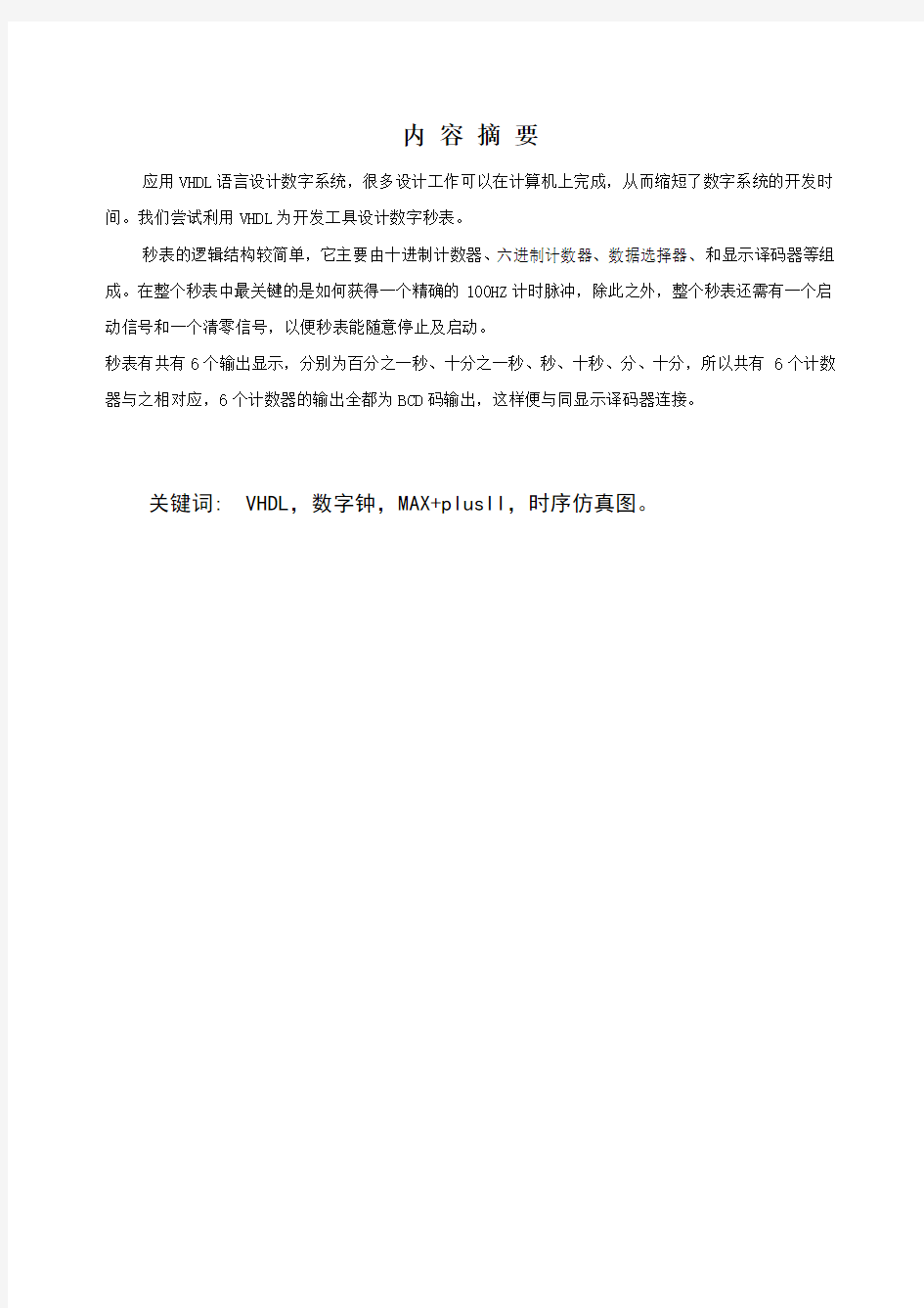
五、数字钟的整体连接图
9
图6. 数字钟各个模块连接示意图
六、实验步骤
(1)安装MAX+plusⅡ软件,为本项设计建立文件夹。
(2)输入设计项目的各个模块,存盘检查,编译并仿真至无误。
(3)调用底层文件的各个模块,连接整体原理图,进行存盘检查,编译仿真至无误。(4)将PC机与试验箱进行连接选择器件并锁定引脚,然后进行编译下载。
(5)按照锁定好的引脚进行连线,进行硬件测试,验证仿真和测试结果。
七、实验结果
通过硬件测试,得到如下测试结果:
(1)数码管能够正确显示时钟数字。
(2)给复位端(reset)低电平时,能够进行复位。
(3)给手动调时(sethour)调分(setmin)信号端高电平时,能够进行调时调分。(4)整点时蜂鸣器能够报时,3只LED灯循环点亮。
八、总结
本次EDA课程设计历时一个星期,一个星期的日子里,可以说是苦多于甜,但是让我学到了很多东西,同时巩固以前所学过的知识,而且还学到了很多在书本上所没有学到过的知识。通过这次设计,进一步加深了对EDA的了解,让我对它有了更加浓厚的兴趣。但是在编调试顶层文件的程序时,遇到了不少问题,特别是各元件之间的连接,以及信号的定义,总是有错误,在细心的检查下,终于找出了错误和警告,排除困难后,程序编译就通过了。在硬件实验时,也遇到了一点困难,想要的结果不能在数码管上得到正确的显示:
在设定输入的时钟信号后,数字秒表开始计数,但是始终是乱码。后来,经过多次调试之后,才发现是因为输入的时钟信号出了问题。经过屡次调试,终于找到了比较合适的输入脉冲,时钟周期设置在100hz秒左右比较合适。
通过这次课程设计使我懂得了理论与实际相结合是很重要的,只有理论知识是远远不够的,只有把所学的理论知识与实践相结合起来,从理论中得出结论,才能真正为社会服务,从而提高自己的实际动手能力和独立思考的能力。在设计的过程中遇到问题,可以说得是困难重重,这毕竟第一次做的,难免会遇到过各种各样的问题,同时在设计的过程中发现了自己的不足之处,对以前所学过的知识理解得不够深刻,掌握得不够牢固。
总的来说,这次设计的数字秒表还是比较成功的,虽然在实际的过程中曾经遇到了大量的问题,但是经过自己的努力,都给妥善解决了,这样的积累对于现在大学生来说是十分宝贵的。希望以后能有更多的动手实践机会,在硬件中发现自己的不足,弥补自己的不足,最终成为一个合格的大学生。最后,特别感谢老师对我的帮助。
九、参考文献
[1]李国洪、胡辉、沈明山.EDA技术与实验.机械工业出版社,2009
[2]闫石.数字电子技术基础(第五版).高等教育出版社,2006
10
指导教师评语及设计成绩
评语
课程设计成绩:
指导教师:
日期:年月日