FatNemo:Building a Resilient Multi-Source Multicast
Fat-Tree
Stefan Birrer,Dong Lu,Fabi′a n E.Bustamante,Yi Qiao,and Peter Dinda
Northwestern University,Evanston IL60201,USA,
{sbirrer,donglu,fabianb,yqiao,pdinda}@https://www.doczj.com/doc/a717680244.html,
Abstract.This paper proposes the idea of emulating fat-trees in overlays for
multi-source multicast applications.Fat-trees are like real trees in that their
branches become thicker the closer one gets to the root,thus overcoming the
“root bottleneck”of regular trees.We introduce FatNemo,a novel overlay multi-
source multicast protocol based on this idea.FatNemo organizes its members into
a tree of clusters with cluster sizes increasing closer to the root.It uses bandwidth
capacity to decide the highest layer in which a peer can participate,and relies
on co-leaders to share the forwarding responsibility and to increase the tree’s
resilience to path and node failures.
We present the design of FatNemo and show simulation-based experimental re-
sults comparing its performance with that of three alternative protocols(Narada,
Nice and Nice-PRM).These initial results show that FatNemo not only mini-
mizes the average and standard deviation of response time,but also handles end
host failures gracefully with minimum performance penalty.
1Introduction
High bandwidth multi-source multicast among widely distributed nodes is a critical capability for a wide range of important applications including audio and video confer-encing,multi-party games and content distribution.Throughout the last decade,a num-ber of research projects have explored the use of multicast as an ef?cient and scalable mechanism to support such group communication applications.Multicast decouples the size of the receiver set from the amount of state kept at any single node and potentially avoids redundant communication in the network.
The limited deployment of IP Multicast[16,17],a best effort network layer mul-ticast protocol,has led to considerable interest in alternate approaches that are imple-mented at the application layer,using only end-systems[14,24,19,32,11,2,10,33,39, 31,35].In an end-system multicast approach participating peers organize themselves into an overlay topology for data delivery.Each edge in this topology corresponds to a unicast path between two end-systems or peers in the underlying Internet.All multicast-related functionality is implemented at the peers instead of at routers,and the goal of the multicast protocol is to construct and maintain an ef?cient overlay for data trans-mission.
Among the end-system multicast protocols proposed,tree-based systems have proven to be highly scalable and ef?cient in terms of physical link stress,state and control overhead,and end-to-end latency.However,normal tree structures have two inherent problems:
Resilience:They are highly dependent on the reliability of non-leaf nodes.Resilience is particularly relevant to the application-layer approach,as trees here are com-posed of autonomous,unpredictable end systems.The high degree of transiency of the hosts1has been pointed out as one of the main challenges for these architec-tures[4].
Bandwidth limitations:They are likely to be bandwidth constrained2as bandwidth availability monotonically decreases as one descends into the tree.The bandwidth limitations of normal tree structures is particularly problematic for multi-source, bandwidth intensive applications.For a set of randomly placed sources in a tree, higher level paths(those closer to the root)will become the bottleneck and tend to dominate response times.Once these links become heavily loaded or overloaded, packets will start to be buffered or dropped.
We have addressed the resilience issue of tree-based systems in previous work[5] through the introduction of co-leaders and the reliance on triggered negative acknowl-edgements(NACKs).In this paper,we address the bandwidth limitations of normal tree overlays.
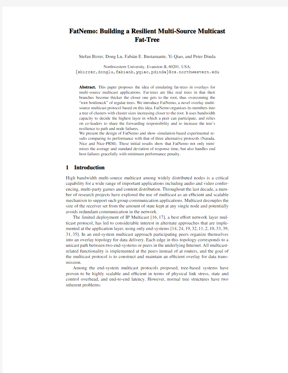
Our approach capitalizes on Leiserson’s seminal work on fat-trees[27].Paraphras-ing Leiserson,a fat-tree is like a real tree in that its branches become thicker the closer we get to the root,thus overcoming the“root bottleneck”of a regular tree.Figure1 shows a schematic example of a binary fat-tree.We propose to organize participant end-systems in a tree that closely resembles a Leiserson fat-tree by dynamically plac-ing higher degree nodes(nodes with higher bandwidth capacity)close to the root and increasing the cluster sizes as one ascends the tree.
This paper makes three main contributions.First,we introduce the use of Leiserson fat-trees for application-layer multi-source multicast,overcoming the inherent band-width limitations of normal tree-based overlay structures(Section2).Second,after re-viewing some background material in Section3,we describe the design and implemen-tation of FatNemo,a new application-layer multicast protocol that builds on this idea (Section4).Lastly,we evaluate the FatNemo design in simulation,illustrating the bene-?ts of a fat tree approach compared to currently popular approaches to application-layer multicast(Sections5and6).We review some related work in Section7and present our conclusion and directions of future work in Section8.
2Fat-Trees and the Overlay
The communication network of a parallel machine must support global collective com-munication operations in which all processors participate[26].These operations have a wide range,including reduction and broadcast trees,and neighbor exchange.All-to-all personalized communication[21],in which each processor sends a unique message to every other processor,is key to many algorithms.To support such operations well,the
Cap. 25 Kbps
Cap. 5 Kbps Cap. 5 Kbps Cap. 5 Kbps
(a)Normal
tree.
Cap. 5 Kbps
Cap. 5 Kbps Cap. 5 Kbps
Cap. 10 Kbps
(b)Fat-tree.
Fig.1.Two binary trees with nodes A and B as sources,publishing at5Kbps each.On the left, a normal binary tree where node E becomes the bottleneck,resulting on a reduced(dash line) outgoing stream quality.Node E has to forward the stream A to node B and node G,as well as stream B to node A and node G,thus it needs an outgoing bandwidth capacity of20Kbps. However,it has only10Kbps available,making it a bottleneck in the tree.On the right,a fat-tree with higher capacity nodes placed higher in the tree.
network should have(1)minimal and scalable diameter,and(2)maximal and scalable bisection bandwidth.These goals are very similar to those of a multisource multicast overlay,which can be thought of as providing many-to-many personalized communica-tion,a subset of all-to-all personalized communication.We expect a multisource multi-cast overlay to have a latency between end-systems that grows only slowly or not at all as the number of end-systems grows.Similarly,we expect the aggregate throughput of the overlay to grow linearly as end-systems are added.
In his seminal work on fat-trees[27],Leiserson introduced a universal routing net-work for interconnecting the processors of a parallel supercomputer,where communi-cation can be scaled independently of the number of processors.Based on a complete binary tree,a fat-tree consists of a set of processors,located at the leaves,and intercon-nected by a number of switching nodes(internal to the tree)and edges.Each edge in the tree corresponds to two unidirectional channels connecting a parent with each of its children.Channel consist of a bundle of wires,and the number of wires in a channel is called its capacity.The capacity of the channels of a fat-tree grows as one goes up the tree from the leaves,thus allowing it to overcome the“root bottleneck”of a regular tree. Since their introduction,fat-trees have been successfully applied in massively parallel systems[28,22]as well as in high performance cluster computing[23].
In this paper we propose to organize the end-systems participant in a multicast group,in an overlay tree that closely resembles a Leiserson fat-tree.In common with Leiserson,our goal is to minimize the mean and standard deviation of inter-node com-munication performance with multiple potential sources.
Emulating fat-trees in an overlay entails a number of challenges such as handling the high level of transiency of end-system populations and addressing their degree of heterogeneity.A straightforward way of approximating a fat-tree is placing those nodes
with higher bandwidth capacity3closer to the root.Since interior nodes are involved in most inter-node communication paths they strongly in?uence the overall end-to-end delay and can soon become bottlenecks as one increases the number of sources.Figure1 shows a schematic example of both a regular binary tree with two5Kbps sources(A and B)and a bottleneck node(E)unable to keep up with the publishing rate of the nodes downstream.
Available bandwidth can differ signi?cantly from bandwidth capacity over time, due typically to competing traf?c,and any algorithm that attempts to emulate fat-trees in an overlay needs to take account of such dynamism.Also,per-path characteristics must be taken into consideration.Since end-to-end latency is an important factor in the performance of interactive applications,the latency of each link in the overlay,the pro-cessing time at each node,and the number of intermediate nodes should be considered carefully.When selecting among possible parents,a closer node may be a better candi-date,if it is able to support the load,than an alternative node offering higher available bandwidth.Finally,the mean time to failure of end-systems is signi?cantly lower than for routers,possibly resulting in long interruptions to the data stream as the failure is discovered and the distribution tree repaired.
Although overlay fat-trees can be built above most tree-based multicast systems, in this paper we consider their implementation using Nemo,a high-resilience,latency-optimized overlay multicast protocol[5].The following section provides some back-ground material on overlay multicast in general and on the operational details of Nemo, before describing the FatNemo design in Section4.
3Background
All peer-to-peer or application-layer multicast protocols organize the participating peers into(1)a control topology for group membership related tasks,and(2)a delivery tree for data forwarding.Available protocols can be classi?ed according to the sequence adopted for their construction[1,13].In a tree-?rst approach[19,24,32],peers directly construct the data delivery tree by selecting their parents from among known peers. Additional links are later added to de?ne,in combination with the data delivery tree, the control topology.With a mesh-?rst approach[13,11],peers build a more densely connected graph(mesh)over which(reverse)shortest path spanning trees,rooted at any peer,can be constructed.Protocols adopting an implicit approach[2,10,33,39,35] create only a control topology among the participant peers.Their data delivery topology is implicitly determined by the de?ned set of packet-forwarding rules.
FatNemo builds on Nemo to emulate a fat-tree;thus,it inherits the latter’s high scal-ability and resilience.In the following paragraphs,we provide a summarized description of Nemo;for more complete details we direct the reader to our previous work[5].
Leader
Fig.2.Nemo’s logical organization.The shape illustrates only the role of a peer within a cluster: a leader of a cluster at a given layer can act as leader,co-leader,or an ordinary member at the next higher layer.
Nemo
Nemo follows the implicit approach to building an overlay for multicasting.The set of communication peers are organized into clusters based on network proximity,where every peer is a member of a cluster at the lowest layer.Clusters vary in size between d and3d?1,where d is a constant known as the degree.Each of these clusters selects a leader that becomes a member of the immediately superior layer.In part to avoid the dependency on a single node,every cluster leader recruits a number of co-leaders to form a supporting crew.The process is repeated at each new layer,with all peers in a layer being grouped into clusters,crew members selected,and leaders promoted to participate in the next higher layer.Hence peers can lead more than one cluster in successive layers of this logical hierarchy.Figure2illustrates the logical organization of Nemo.
A new peer joins the multicast group by querying a well-known special end-system, the rendezvous point,for the identi?er of the root node.Starting there and in an iterative manner,the incoming peer continues:(i)requesting the list of members at the current layer from the cluster’s leader,(ii)selecting from among them who to contact next based on the result from a given cost function,and(iii)moving into the next layer. When the new peer?nds the leader with minimal cost at the bottom layer,it joins the associated cluster.
Member peers can leave Nemo in a graceful manner(https://www.doczj.com/doc/a717680244.html,er disconnects)or in an ungraceful manner(unannounced,e.g.when the end-system crashes).For graceful departures,since a common member has no responsibilities towards other peers,it can simply leave the group after informing its cluster’s leader.On the other hand,a leader must?rst elect replacement leaders for all clusters it owns before it leaves the session.
To detect unannounced departures,Nemo relies on heartbeats exchanged among the cluster’s peers.Unreported members are given a?xed time interval before being considered dead,at which point a repair algorithm is initiated.If the failed peer happens to be a leader,the tree itself must be?xed,the members of the victim’s cluster must elect the replacement leader from among themselves.
To deal with dynamic changes in the underlying network,every peer periodically checks the leaders of the next higher layers and switches clusters if another leader has
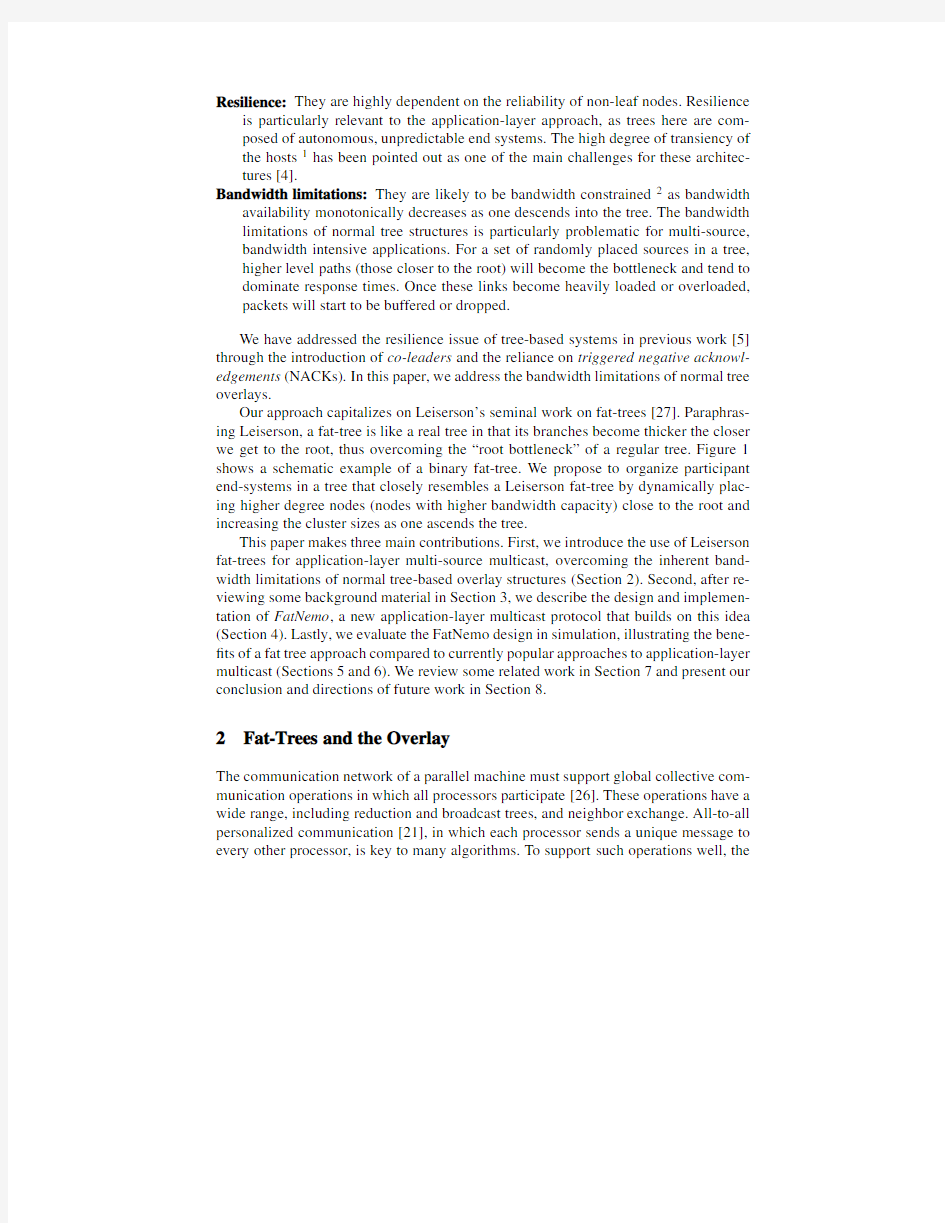
Fig.3.FatNemo’s Topology.The?gure illustrates how the tree gets fatter when moving toward the root.This tree has a cluster degree of2.
a lower cost(i.e.lower latency)than the current one.Additionally,in a continuous process of re?nement,every leader checks its highest owned cluster for better suited leaders and transfers leadership if such a peer exists.
Nemo addresses the resilience issue of tree-based systems through the introduc-tion of co-leaders.Co-leaders improve the resilience of the multicast group by avoiding dependencies on single nodes and providing alternative paths for data forwarding.In addition,crew members share the load from message forwarding,thus improving scal-ability.
4FatNemo Design
To build an overlay fat-tree,FatNemo relies on three heuristics:(1)higher bandwidth degree nodes should be placed higher up in the tree,(2)all peers must serve as crew members in order to maximize load balancing,and(3)the size of clusters should in-crease exponentially as one ascends the tree.The following paragraphs provide the motivations behind each of these heuristics.
The per-node bandwidth constraint is critical for bandwidth-demanding applica-tions and can be stated as the number of full-rate streams a peer is able to support, i.e.its out-degree.By organizing peers based on their out-degrees[36,13],we intend to reduce the bandwidth constraints of links higher up the tree.Since the process of estimating available bandwidth is time consuming,peers initially join the tree based on proximity.Once in the tree,every leader checks its highest owned cluster for better suited leaders in terms of bandwidth availability,and transfers leadership if such a peer exists.This process assures that high out-degree peers will gradually ascend to higher layers,thus transforming the tree into a bandwidth optimized fat-tree.
In traditional fat-trees the number of wires increases as one ascends the tree.Con-sidering an overlay unicast connection as a“wire”,the number of wires in FatNemo increases together with the crew size as one moves toward the root–the maximum possible number of wires is thus achieved by setting the crew size equal to the cluster
Table1.Cluster and Crew Size as a function of the cluster degree d,for a20,000peer population. The variable x is a place holder for the cluster index starting at0for the lowest layer.
Protocol Crew Size c(x)
d...3d?11
Nemo d=3:3 (8)
d x+1...2d x+1+2k(x)
size.The size of a cluster at layer i in FatNemo varies between d i and2d i+2,and
grows exponentially(d i=d i+1
0)as we move up the layers.The0-th layer contains the
leaf nodes and has a degree d0of3(same as Nice and Nemo).The increased number of wires helps avoid higher level links from becoming the bottleneck of the system,as alternate paths share the load and reduce the forward responsibility of each peer.
Beyond increasing the number of wires,large crew sizes also help reduce the depth of a tree(when compared with its constant cluster-sizes equivalent).A smaller depths means a lower total number of end-system hops,and should translate in a reduction on the end-to-end delay.
Figure3illustrates how FatNemo constructs a fat-tree.In this simple example d0= 2,so clusters scale up by a factor of2as we ascend the tree.Notice that these links/wires are indeed(d i+1...2d i+1+2)to(d i...2d i+2)relations,as every crew member of the next higher layer will talk to the crew members of the immediately lower layer.For clarity in the graph,this set of links is represented in the graph by d i lines.
To better understand the positive effect of FatNemo’s heuristics,we show an instan-tiation of them with a population of20,000peers from a popular on-line game.4 To begin,let’s generalize the concept of out-degree.The out-degree of a peer,d out, is equivalent to the total forwarding responsibility of a node,and it can be stated as a function of the number of layers L in which the node participates,the cluster size k(x) and the crew size c(x)at layer x(Equation(1)).Table1illustrates the parameter values for FatNemo and two alternative protocols.
d out=L?1
x=0
k(x)?1
4The number corresponds to the active populations of players in https://www.doczj.com/doc/a717680244.html,,an online soccer game.
5The average number of peers in a cluster is equal to the mean cluster size,which can be computed as the mean of the low and high cluster boundary.
Based on the expected depth of the different trees for this example population,we can now calculate the out-degree requirements on their root nodes.According to the generalized out-degree equation introduced in the previous paragraph(Equation(1)), Nice requires a root out-degree of31.5,or almost three times more than what is needed from a Nemo’s root(10.5)with a crew size of3.In other words,the root of a traditional tree for a20,000peer population must support31.5times the source rate to ful?ll its forwarding responsibility!By emulating a fat-tree in the overlay,FatNemo avoids this “root bottleneck”requiring only a root with an out-degree of3.7.
5Evaluation
We analyze the performance of FatNemo through simulation and compare it to that of three other protocols–Narada[14],Nice[2]and Nice-PRM[3].We evaluate the effectiveness of the alternative protocols in terms of performance improvements to the application and protocol’s overhead,as captured by the following metrics: Response Time:End-to-end delay(including retransmission time)from the source to the receivers,as seen by the application.This includes path latencies along the overlay hops,as well as queueing delay and processing overhead at peers along the path.A lower mean response time indicates a higher system responsiveness,and a smaller standard deviation implies better synchronization among the receivers. Delivered Packets:Number of packets successfully delivered to all subscribers within a ?xed time window.It indirectly measures the protocol’s ability to avoid bottlenecks in the delivery tree.
Delivery Ratio:Ratio of subscribers that have received a packet within a?xed time window.Disabled receivers are not accounted for.
Duplicate Packets:Number of duplicate packets per sequence number,for all enabled receivers,re?ecting an unnecessary burden on the network.Packets arrived outside of the delivery window are accounted for as duplicates,since the receiver already assumed them as lost.
Control-Related Traf?c:Total control traf?c in the system,in mega bits per second (Mbps);part of the system’s overhead.We measure the total traf?c during the observation interval by accounting packets at the router level.A network packet traversing four routers(including the source and destination node)will account as three sent packets,one for every router which has to forward it.
The remainder of this section brie?y discusses implementation details of the com-pared protocols and describes our evaluation setup.Section6presents our evaluation results.
5.1Details on Protocol Implementations
For each of the three alternative protocols,the values for the available parameters were obtained from the corresponding literature[13,2,3].
For Narada[13],we employ the bandwidth-only scheme for constructing the over-lay,as this will result in maximum throughput.For Nice[2]and Nice-PRM[3],the
cluster degree,k,is set to3.We use Nice-PRM(3,0.02)with three random peers chosen by each node,and with two percent forwarding probability.
For FatNemo,the cluster degree at the lowest layer is set to three.Cluster degree grows exponentially with every layer,being nine in the second lowest layer,27in the third,and so on.
Our implementations of the alternative protocols closely follow the descriptions from the literature,and have been validated by contrasting our results with the pub-lished values.However,there are a number of improvements to the common algorithms, such as the use of periodic probabilistic maintenance operations,that while part of Fat-Nemo,were made available to all protocols in our evaluations.The bene?ts from these algorithms help explain the performance improvements of the different protocols with respect to their original publications[13,2,3].
5.2Experimental Setup
We performed our evaluations through detailed simulation using SPANS,a locally writ-ten,packet-level,event-based simulator.Simulations were run using GridG[29,30] topologies with5510,6312and8115nodes,and a multicast group of256members. GridG leverages Tiers[18,8]to generate a three-tier hierarchical network structure, before it applies a power law enforcing algorithm that retains the hierarchical structure.
Members were randomly associated with end systems,and a random delay of be-tween0.1and80ms was assigned to every link.The links use drop-tail queues with a buffer capacity of0.5sec.We con?gured GridG to use different bandwidth distributions for different link types[25].We assume that the core of the Internet has higher band-width capacities than the edge,as shown in Fig.4.In all three scenarios,the bandwidth has a uniform distribution with ranges shown in Fig.4.
Fig.4.Three simulation scenarios:Low-,Medium-and High-Bandwidth.Bandwidth is expressed in Kbps.
Scenario End systems Client-Stub Transit-Stub
Low-B/W5000400-60004000-10000
312127304000-1000015000-30000 High-B/W75001000-1500010000-50000
# Publishers D e l i v e r e d P a c k e t s Fig.5.Delivered packets (256end hosts,Low-Bandwidth scenario).
mean time to repair (MTTR)equal to 10min.).The two means were chosen asymmet-rically to allow,on average,6/7of all members to be up during this phase.The failure event sequence was generated a priori based on the above distribution and used for all protocols and all runs.
In all experiments,we model multi-source multicast streams to a group.Each source sends constant bit rate (CBR)traf?c of 1000Byte payload at a rate of 10packets per second.The buffer size was set to 16packets,which corresponds to the usage of a
1.6-second buffer,a realistic scenario for applications such as video conferencing.6Experimental Results
This section presents early evaluation results of FatNemo and compares them with those of three alternative protocols.The reported results are from ?ve runs per protocol ob-tained with the different GridG topologies and the Low-Bandwidth scenario.Similar results were obtained with the Mid-and High-Bandwidth scenarios.
Figure 5shows the average number of delivered packets of all runs with no host failures.As we increase the number of publishers,the protocol’s data delivery topology collapses.This happens ?rst for Narada,which is unable to handle the full publishing rate from one publisher.Nice and Nice PRM handle an increasing number of publishers better;however,they deliver substantially fewer packets when compared with FatNemo.FatNemo is best at avoiding bottlenecks in the delivery tree,delivering the most packets when the network is overloaded (as seen with 8publishers).
The performance of a multi-source multicast system can be measured in terms of mean and standard deviation of the response time.Table 2shows these two metrics for the evaluated protocols with one publisher.FatNemo outperforms Nice,Nice PRM and Narada in terms of mean and standard deviation of response time.With an increased number of publishers the relative number of delivered packets for Nice,Nice PRM and Narada decreases compared to FatNemo,which makes it impossible to fairly compare
Table2.Response Time(1Publisher,256end hosts,Low-Bandwidth scenario).
Protocol Std
0.158
0.183
0.195
0.770
No Failures
FatNemo0.966
Nice0.956
Nice-PRM(3,0.02)0.970
Narada0.648
Table4.Overhead(1Publisher,256end hosts,Low-Bandwidth scenario).
Protocol Control Traf?c[Mbps]
0.367
0.000
5.168
0.006
improve the resilience of the overlay and adopts a periodic probabilistic approach to reduce/avoid the cost of membership operations.
A new set of projects have started to address the resilience of overlay multicast protocols[3,9,35,5,31,38].ZigZag[35],a single-source protocol,explores the idea of splitting the control and data delivery task between two peers in each level,making both responsible for repairs under failures.With PRM[3]Banerjee et al.propose the use of probabilistic forwarding and NACK-based retransmission to improve resilience. In order to reduce the time-to-repair,Yang and Fei[38]argue for proactively,ahead of failures,selecting parent replacements.CoopNet[31]improves resilience by building several disjoint trees on a centralized organization protocol and employing Multiple De-scription Coding(MDC)for data redundancy.Nemo[5]and FatNemo build redundancy into the overlay through co-leaders;different from the previously described protocols, they make all crew members share forwarding responsibilities while all cluster mem-bers are in charge of repair operations.These simple measures enable an uninterrupted service to downstream peers especially during recovery intervals.We are currently ex-ploring the use of data redundancy using forward error correction(FEC)encoding[6].
Aiming at bulk data distribution,protocols such as Splitstream[9],Bittorrent[15] and Bullet[25]have proposed simultaneous data streaming over different paths to better share the forwarding load and increased downloading capacity.The methods differ in how they locate alternate streaming peers.In comparison,FatNemo exploits alternate paths for resilience and load balancing.
8Conclusions and Further Work
In this paper we introduced the parallel architecture concept of fat trees to overlay mul-ticast protocols.We have described FatNemo,a novel scalable peer-to-peer multicast protocol that incorporates this idea to build data delivery topologies with minimized mean and standard deviation of the response time.Simulation results show that Fat-Nemo can achieve signi?cantly higher delivery ratios than alternative protocols(an in-crease of up to360%under high load),while reducing the mean(by up to80%)and standard deviation(by up to84%)of the response time in the non-overloaded case. Under a heavy load and a realistic host failure rate,the resulting protocol is able to at-tain high delivery ratios with negligible cost in terms of control-related traf?c.We are currently validating our?ndings through wide-area experimentation. Acknowledgments
We are grateful to Janine M.Casler,Kevin Livingston and Ananth Sundararaj for their helpful comments on early drafts of this paper.
References
1.S.Banerjee and B.Bhattacharjee.A comparative study of application layer multicast proto-
cols,2002.Submitted for review.
2.S.Banerjee,B.Bhattacharjee,and C.Kommareddy.Scalable application layer multicast.In
Proc.of ACM SIGCOMM,August2002.
3.S.Banerjee,S.Lee,B.Bhattacharjee,and A.Srinivasan.Resilient multicast using overlays.
In Proc.of ACM SIGMETRICS,June2003.
4.M.Bawa,H.Deshpande,and H.Garcia-Molina.Transience of peers&streaming media.In
Proc.of HotNets-I,October2002.
5.S.Birrer and F.E.Bustamante.Nemo-resilient peer-to-peer multicast without the cost.
Tech.Report NWU-CS-04-36,Northwestern U.,April2004.
6.R.E.Blahut.Theory and Practice of Error Control Codes.Addison Wesley,1994.
7. F.E.Bustamante and Y.Qiao.Friendships that last:Peer lifespan and its role in P2P proto-
cols.In Proc.of IWCW,October2003.
8.K.L.Calvert,M.B.Doar,and E.W.Zegura.Modeling internet topology.IEEE Communi-
cations Magazine,35(6):160–163,June1997.
9.M.Castro,P.Druschel,A.-M.Kermarrec,A.Nandi,A.Rowstron,and A.Singh.Splitstream:
High-bandwidth multicast in cooperative environments.In Proc.of the19th ACM SOSP, October2003.
10.M.Castro,A.Rowstron,A.-M.Kermarrec,and P.Druschel.SCRIBE:A large-scale and
decentralised application-level multicast infrastructure.IEEE Journal on Selected Areas in Communication,20(8),2002.
11.Y.Chawathe.Scattercast:an architecture for Internet broadcast distribution as an infras-
tructure service.Ph.D.Thesis,U.of California,Berkeley,CA,Fall2000.
12.Y.-H.Chu,A.Ganjam,T.S.E.Ng,S.G.Rao,K.Sripanidkulchai,J.Zhan,and H.Zhang.
Early experience with an Internet broadcast system based on overlay multicast.In Proc.of USENIX ATC,June2004.
13.Y.-H.Chu,S.G.Rao,S.Seshan,and H.Zhang.A case for end system multicast.IEEE
Journal on Selected Areas in Communication,20(8),October2002.
14.Y.-H.Chu,S.G.Rao,and H.Zhang.A case for end system multicast.In Proc.of ACM
SIGMETRICS,June2000.
15. https://www.doczj.com/doc/a717680244.html,/BitTorrent/,2001.File distribution.
16.S.E.Deering.Multicast routing in internetworks and extended LANs.In Proc.of ACM
SIGCOMM,August1988.
17. C.Diot,B.N.Levine,B.Lyles,H.Kassem,and D.Balensiefen.Deployment issues for the
IP multicast service and architecture.IEEE Network,14(1),January/February2000.
18.M.B.Doar.A better model for generating test networks.In Proc.of Globecom,November
1996.
19.P.Francis.Yoid:Extending the Internet multicast architecture.https://www.doczj.com/doc/a717680244.html,/yoid,
April2000.
20.K.P.Gummadi,R.J.Dunn,S.Saroiu,S.D.Gribble,H.M.Levy,and J.Zahorjan.Mea-
surement,modeling and analysis of a peer-to-peer?le-sharing workload.In Proc.of ACM SOSP,December2003.
21.S.Hinrichs,C.Kosak,D.O’Hallaron,T.Stricker,and R.Take.An architecture for optim-
imal all-to-all personalized communication.In Proceedings of the6th ACM Symposium on Parallel Algorithms and Architectures(SPAA),pages310–319,1994.
22.M.Homewood and M.McLaren.Meiko CS-2interconnect elan–elite design.In IEEE Hot
Interconnects Symposium,August1993.
23.In?niBand Trade Association.In?niband architecture speci?cation(1.0.a).
www.in?https://www.doczj.com/doc/a717680244.html,,June2001.
24.J.Jannotti,D.K.Gifford,K.L.Johnson,M.F.Kaashoek,and J.W.O’Toole Jr.Overcast:
Reliable multicasting with and overlay network.In Proc.of the4th USENIX OSDI,October 2000.
25. D.Kosti′c,A.R.adn Jeannie Albrecht,and A.Vahdat.Bullet:High bandwidth data dissem-
ination using an overlay mesh.In Proc.of the19th ACM SOSP,October2003.
26.T.Leighton.Introduction to Parallel Algorithms and Architectures:Arrays,Trees,Hyper-
cubes.Morgan Kaufmann,1992.
27. C.E.Leiserson.Fat-trees:Universal networks for hardware-ef?cient supercomputing.IEEE
Transactions on Computers,34(10):892–901,October1985.
28. C.E.Leiserson,Z.S.Abuhamdeh,D.C.Douglas,C.R.Feynman,M.N.Ganmukhi,J.V.
Hill,W.D.Hillis,B.C.Kuszmaul,M.A.S.Pierre,D.S.Wells,M.C.Wong-Chan,S.-W.
Yang,and R.Zak.The network architecture of the Connection Machine CM-5.Journal of Parallel and Distributed Computing,33(2):145–158,1996.
29. D.Lu and P.A.Dinda.GridG:Generating realistic computational grids.ACM Sigmetrics
Performance Evaluation Review,30(4):33–41,March2003.
30. D.Lu and P.A.Dinda.Synthesizing realistic computational grids.In Proc.of SC2003,
November2003.
31.V.N.Padmanabhan,H.J.Wang,and P.A.Chou.Resilient peer-to-peer streaming.In Proc.
of IEEE ICNP,2003.
32. D.Pendarakis,S.Shi,D.Verma,and M.Waldvogel.ALMI:An application level multicast
infrastructure.In Proc.of USENIX USITS,March2001.
33.S.Ratnasamy,M.Handley,R.Karp,and S.Shenker.Application-level multicast using
content-addressable networks.In Proc.of NGC,November2001.
34.S.Rhea,D.Geels,T.Roscoe,and J.Kubiatowicz.Handling churn in a DHT.In Proc.of
USENIX ATC,December2004.
35. D.A.Tran,K.A.Hua,and T.Do.ZIGZAG:An ef?cient peer-to-peer scheme for media
streaming.In Proc.of IEEE INFOCOM,April2003.
36.Z.Wang and J.Crowcroft.Bandwidth-delay based routing algorithms.In Proc.of IEEE
GlobeCom,November1995.
37.J.Xu,Z.Kalbarczyk,and https://www.doczj.com/doc/a717680244.html,worked Windows NT system?eld failure data
analysis.In Proc.of PRDC,December1999.
38.M.Yang and Z.Fei.A proactive approach to reconstructing overlay multicast trees.In Proc.
of IEEE INFOCOM,March2004.
39.S.Q.Zhuang,B.Y.Zhao,A.D.Joseph,R.H.Katz,and J.D.Kubiatowicz.Bayeux:An
architecture for scalable and fault-tolerant wide-area data dissemination.In Proc.of NOSS-DAV,June2001.
公司组织原则及组织机构设置原则 一、公司的组织原则 公司组织原则是指为了实现有效管理职能、提高管理效率和实现—定的 目标而建立管理机构共同遵循的原则。主要有以下几个方面: (一)目标一致原则。公司及各部门的目标必须和决策层确定的目标保 持高度一致,这是公司提高效能的前提条件,也是团结和鼓舞全体员工同心 协力地完成预定目标的动力。 (二)职责分明原则。组织中职权分明,使每一项管理职能都能落实到 一个执行机构。职责不要分散,不能实行多头领导,造成互相扯皮推诿。组 织的职能定位、个人的职责定位是相当明确的,要把握好角色定位,不失职、不越位是基本要求,坚守本职是核心要求。 (三)责权对等原则。无论组织还是管理者个人(组织是职能、管理者 是职责),只要你担负一定的责任,组织就会授予你相应的权力,以保证你 合法有效地履行你的职责。管理人员、员工所拥有的权力应当与其所承担的 责任一致,权力与其承担的责任应该对等,同时要使员工知道具体的责任内 容、权力范围和利益大小。 (四)协调原则。机构要互相协调、互相衔接,有利发挥组织整体功能, 使组织内部既有分工,又有合作,协调一致,实现一个共同目标。 (五)组织阶层原则。实行统一领导,分级管理,集权与分权结合。要 确定科学的管理幅度和管理层次。要坚持必要的集中统一领导,使企业领导 人指挥决策的实施有效而迅速。又要实行分级管理,调动各方面的积极性。 (六)控制幅度原则。在处理管理幅度与管理层级的关系时,应尽量减 少管理层级。适当的组织扁平化可通过破除公司自上而下的垂直高耸的结 构,减少管理层次,增加管理幅度,裁减冗员来建立一种紧凑的横向组织, 达到使组织变得灵活、敏捷、富有柔性、创造性的目的。但过度扁平化会出 现领导及管理部门的协调工作量大幅度增加、公司运营灵活性受限等阻碍公 司发展的情况。
机械原理课程设计说明书 ——平台印刷机主传动机构运动简图设计设计名称平台印刷机主传动机构运动简图设计 专业机械设计制造及其自动化 08622班 姓名 指导教师 时间2010-7-7
目录 一、设计题目 (3) 1、设计条件与要求 (3) 2、原理图 (3) 二、机械运动方案的选择 (3) 1、平台印刷机主要机构及功能 (3) 2、实现功能的方案 (4) 3、设计方案的拟定和比较及设计思路概述 (4) 4、平台印刷机设计数据 (5) 三、对选定机构的运动分析与设计 (5) 1、曲柄滑块机构综合分析 (5) (1)机构的运动几何关系 (5) (2) 参数选择 (6) 2、双曲柄机构的运动分析 (7) (1)曲柄滑块位移计算Ψ (7) (2)由Ψ1求Ψ3 (8) 3、曲柄滑块机构的位置分析 (8) 4、凸轮机构的设计 (9) (1)凸轮机构从动件运动规律的确定 (9) (2)绘制补偿凸轮轮廓 (10) 四、程序设计 (10) 1、所调用的子程序及功能 (10) 2、所编程序的框图 (11) 3、主程序如下 (13) 4、主程序子程序中主要参数说明 (16) 5、程序运行结果 (17) 6、版台位移,速度以及滚筒位移,速度曲线 (17) 五、总结 (17) 六、参考文献 (18)
一、设计题目 1、设计条件与要求 工作原理:平台印刷机的工作过程由输纸,着墨,压印和收纸四部分组成,主运动是压印,由卷有空白纸张的滚筒与镶着铅字的版台之间纯滚动来完成。滚筒与版台表面之间的滑动会造成字迹模糊,是不允许的。因此,对运动的主要要求是:其一,版台的移动速度严格等于滚筒表面的圆周速度;其二,为了提高生产率,要求版台的运动有急回特性。有一台电动机驱动。需设计满足上述两个要求的传动机构。执行件的运动为滚筒连续转动和版台往返移动。 2、原理图 图1 二、机械运动方案的选择 1、平台印刷机主要机构及功能 主要机构: 1) 传动机构I——从电动机到版台的运动链;
先教大家一些基础知识,学习破解其实是要和程序打交道的,汇编是破解程序的必备知识,但有可能部分朋友都没有学习过汇编语言,所以我就在这里叫大家一些简单实用的破解语句吧! ---------------------------------------------------------------------------------------------------------------- 语句:cmp a,b //cmp是比较的意思!在这里假如a=1,b=2 那么就是a与b比较大小. mov a,b //mov是赋值语句,把b的值赋给a. je/jz //就是相等就到指定位置(也叫跳转). jne/jnz //不相等就到指定位置. jmp //无条件跳转. jl/jb //若小于就跳. ja/jg //若大于就跳. jge //若大于等于就跳. 这里以一款LRC傻瓜编辑器为例,讲解一下软件的初步破解过程。大家只要认真看我的操作一定会!假如还是不明白的话提出难点帮你解决,还不行的话直接找我!有时间给你补节课!呵呵! 目标:LRC傻瓜编辑器杀杀杀~~~~~~~~~ 简介:本软件可以让你听完一首MP3歌曲,便可编辑完成一首LRC歌词。并且本软件自身还带有MP3音乐播放和LRC歌词播放功能,没注册的软件只能使用15天。 工具/原料 我们破解或给软件脱壳最常用的软件就是OD全名叫Ollydbg,界面如图: 它是一个功能很强大的工具,左上角是cpu窗口,分别是地址,机器码,汇编代码,注释;注释添加方便,而且还能即时显示函数的调用结果,返回值. 右上角是寄存器窗口,但不仅仅反映寄存器的状况,还有好多东东;双击即可改变Eflag的值,对于寄存器,指令执行后发生改变的寄存器会用红色突出显示. cpu窗口下面还有一个小窗口,显示当前操作改变的寄存器状态. 左下角是内存窗口.可以ascii或者unicode两种方式显示内存信息. 右下角的是当前堆栈情况,还有注释啊. 步骤/方法 1. 我们要想破解一个软件就是修改它的代码,我们要想在这代码的海洋里找到我们破解关键的代码确实很棘 手,所以我们必须找到一定的线索,一便我们顺藤摸瓜的找到我们想要的东东,现在的关键问题就是什么
选择板式换热器要注意以下三个事项 1、板式换热器板型的选择板片型式或波纹式应根据换热场合的实际需要而定。对流量大允许压降小的情况,应选用阻力小的板型,反之选用阻力大的板型。根据流体压力和温度的情况,确定选择可拆卸式,还是钎焊式。确定板型时不宜选择单板面积太小的板片,以免板片数量过多,板间流速偏小,传热系数过低,对较大的换热器更应注意这个问题。艾瑞德每种规格的板片,均具有至少两个板型,采用热混合技术,可以综合换热器的传热和压降,使其运行在最佳工作点。内旁通,双流道技术和不等流通截面积装配为两侧介质流量相差较大的工况提供了完美的解决方案。ARD艾瑞德板式换热器(江阴)有限公司板式换热器有AB系列、AM系列、AL系列、AP系列、AS系列等几大系列百余种板型。各种型号都有深波纹、浅波纹、大角度、小角度等,完全确保满足不同用户的需要,特殊工况可按用户需要专门设计制造。 2、流程和流道的选择流程指板式换热器内一种介质同一流动方向的一组并联流道,而流道指板式换热器内,相邻两板片组成的介质流动通道。一般情况下,将若干个流道按并联或串联的费那个是连接起来,以形成冷、热介质通道的不同组合。流程组合形式应根据换热和流体阻力计算,在满足工艺条件要求下确定。尽量使冷、热水流道内的对流换热系数相等或接近,从而得到最佳的传热效果。因为在传热表面两侧对流换热系数相等或接近时传热系数获得较大值。虽然板式换热器各板间流速不等,但在换热和流体阻力计算时,仍以平均流速进行计算。由于“U”形单流程的接管都固定在压紧板上,拆装方便。 3、压降校核在板式换热器的设计选型使,一般对压降有一定的要求,所以应对其进行校核。如果校核压降超过允许压降,需重新进行设计选型计算,直到满足工艺要求为止。 艾瑞德板式换热器(江阴)有限公司是专业生产可拆式板式换热器(PHE)、换热器密封垫(PHE GASKET)、换热器板片(PHE PLATE)并提供板式
问题背后的问题——组织结构变革设计 来源:网络 当企业出现经营业绩逐渐下滑、产品质量迟迟不能提高、浪费和消耗严重、新的管理措施总是难以实施、管理效率下降、员工不满情绪增加等等诸多问题的时候,企业家们首先想到的是什么?常见的思考方式会认为,这些可能是人员素质问题、激励措施问题、绩效考核问题或者是制度不完善,更进一步的,或许还会认为是企业战略不清晰、是企业执行力不够或者是企业文化需要重塑?于是,企业往往会采取执行力培训、文化重塑、战略转型、绩效管理改革、薪资改革等等手段,甚至会解聘和更换员工。 这些措施本身毫无问题,但是却往往只能起到短暂的作用,甚至解聘和更换员工都无法彻底解决问题。那么,究竟是什么困扰着企业的发展?我们需要找到问题背后的问题。 一、问题背后的问题——组织结构不合适才是根源 当企业出现病症的时候,最容易被忽视但却可能是最根本的问题是,企业的组织结构不再适合企业的发展。 之所以容易被忽视,是因为在传统的管理理论中我们通常认为,有很多合理的组织结构模型可以供选择:例如职能制、矩阵式、事业部制、母子公司体制、超矩阵式等。所以在组织结构设计的时候,企业家们会自觉或不自觉的采取一种耳熟能详的或者公认的组织结构形式。尤其是当看到很多成功的企业也在采用类似的组织结构时,企业家们会更加安心。 但是完美的组织结构理论这一温情脉脉的面纱背后,冰冷的现实时刻在提醒我们,不存在一种普适的、绝对正确的组织结构。组织结构的本质是为了实现企业战略目标而进行的分工与协作的安排,它是让人们有效的一起工作的工具。因此,不同的战略、不同的时期、不同的环境必然需要配合不同的组织结构。 不同的战略:组织结构是战略实施的载体,战略不同组织结构必然随之调整。就像蜗牛与羚羊,蜗牛的战略是当危险来临就缩进硬壳里面,所以蜗牛需要背着房子到处走;羚羊的战略是当危险来临就要快速奔跑离开,所以羚羊就需要强健的四肢。如果让羚羊背上房子,又怎么能实施快速奔跑的战略呢? 不同的发展阶段:在企业发展的不同阶段,随着组织规模的扩大和能力的改变,组织结构也需要相应变革来适应组织的发展。在创业阶段,企业需要快速反应来保证生存,组织结构需要简单,围绕主要职能来设置部门,如果组织结构过于臃肿、部门过多,就会造成流程割裂、效率低下,企业的生存就会出现问题。当企业发展壮大,如果仍然粗略的设置组织结构,就会造成重要职能薄弱或缺失,企业就会缺乏相应的能力,企业的发展就会受到影响。就像人小的时候,如果穿过大的鞋,就会举步维艰,怎么也跑不快;当长大成人,如果再穿小时候的鞋,跑的过程中一定会受到束缚、疼痛难忍。
板式换热器的技术参数 更新日期:2012-12-12 进出口管径进出口管径的大小以介质在管道内的活动速度小于3m/S为宜来确定,最大流速宜小于4m/s。现海内板式板式换热器板片厚度一股为0.5~1.0mm,考虑到厂家制造工艺、现场操纵水平及侵蚀、除垢等因素,板式换热器板片厚度宜选择0.7~0.9ram。 板式换热器软水侧压力损失 软化水进出板式换热器温度根据现有高炉软水供给的经验,软水供给温度在3 5~40℃之间时,对高炉稳产高产、安全出产最有利,同时考虑到夏季冷媒水及冷却塔的冷却能力,软化水进高炉温度在夏季最不利工况时宜小于40℃,软化水出高炉温度宜小于4 5℃,即软化水进板式换热器温度宜为4 5℃,出板式换热器温度宜为40℃。 板式换热器板片材质板式板式换热器板片材质基本上采用不锈钢、钛合金两种。 板式板式换热器数目根据中小高炉的特点,其炉体冷却软水系统采用板式板式换热器的数目宜为3台并联,每台流量为最大流量的5O%,正常运行开二备一。 冷却水进、出板式换热器温度根据夏季冷却水供水温度及冷却塔工作能力,冷却水进板式换热器温度宜小于32℃,出板式换热器温度宜小于3 7℃。 流量根据水在冷却壁的公道流速,并重点考虑高炉后期内壁耐热层减薄、传热量急剧增加的情况,按后期最大传热量来确定软化水流量。因为钛材料价格为不锈钢的4~6倍,且高炉冷却系统板式板式换热器板片材质采用不锈钢即可知足要求,为此板式板式换热器板片材质选用不锈钢。 板式换热器正常工作压力根据软水系统闭路轮回的特点,板式换热器正常工作压力最小值应为软水系统轮回水泵出口压力与高炉高位膨胀水箱水位高度之和。原有空冷器软水侧压力损失小于0.05MPa,因此板式板式换热器软水侧压力损失必需小于’0.05M Pa。 密封垫材质考虑现场实际情况及板式板式换热器工作温度、软化水成分等诸多因素,密封垫材质宜选用三元乙丙橡胶。 因为软水系统除停开空冷器、并入板武板式换热器外,其它部门不变,因此,板式板式换热器软水侧压力损失须小于原有空冷器软水侧压力损失。 板式换热器板片厚度板式换热器板片厚度与传热系数成反比关系,板片厚度越小,传热效果越好,但同时也轻易侵蚀泄漏。 ARD拥有世界上最先进的设计和生产技术以及最全面的换热器专业知识,有专门的选型软件根据用户不同工况测算出最适合的板式换热器。
(二)板式换热器 3设计与运行条件 3.1板式换热器型式 板式换热器采用等截面可拆卸板式换热器(水-水),换热面材质材质为GB316不锈钢。 3.2板式换热器的配置 本次招标共需配备2台可拆卸板式换热器(水-水),单台功率22.5MW,单台换热面积950㎡,换热器接管管径按设计所提管径配置,换热器按本技术规书所提面积订货。 3.3板式换热器设计参数 下表为单台22.5兆瓦板式换热器的参数
3.4热网循环水水质 板式换热器工作介质为热网循环水,水质为软化水,具体水质如下:
3.5运行方式 板式换热器并联运行。 板式换热器换热量的控制通过控制一次侧(高温介质)流量和控制二次侧(低温介质)流量来实现。 3.6设备的安装地点及标高 板式换热器安装在换热站0米层。 4技术要求 投标方提供的板式换热器设计、制造、检验与验收应满足国家相关规中的相关规定,同时应满足本技术规书术要求,如有矛盾时按较高要求执行。 4.1板式换热器性能要求 4.1.1投标方所提供的板式换热器是可拆卸板式换热器(水-水),其技术先进、经济合理,成熟可靠的产品,具有较高的运行灵活性。 4.1.2板式换热器能在最大工况点长期连续运行,能满足板式换热器不同运行工况的需要,并且预留能增加10%换热能力板片的安装空间和技术条件。 4.1.3板式换热器不宜选择单板面积太小的板片,避免板片数量过多,要求单板面积大于等于2.5㎡。 4.1.4板式换热器采用板型应使换热器流体充分湍动,防止板片表面结垢。 4.1.5板式换热器应选用阻力小的板型,保证一次侧(高温介质)压降不大于0.03MPa,二次侧(低温介质)压降不大于0.03MPa。 4.1.6板式换热器板片厚度应不小于0.7mm。 4.1.7板式换热器额定工况运行时,二次侧(低温介质)出口温度偏差不应出现负偏差。 4.1.8板片波纹形式应采用技术成熟、有成功使用业绩的波纹形式。 4.1.9板式换热器外部、部保证不泄漏,一、二次水禁止混流。
①战略匹配原则 一方面,战略决定组织结构,有什么样的战略就有什么样的组织结构;另一方面,组织结构又支持战略实施,组织结构是实施战略的一项重要工具,组织结构是随着战略而定的,它必须根据战略目标的变化而及时调整。通常情况下组织根据近期和中长期发展战略需要制订近期和中远期组织结构 ②顾客满意原则 顾客是组织赖以生存和发展的载体,组织设计的组织架构和业务流程必须是以提高产品和服务,满足顾客需求为中心的。要确保设计的组织架构和流程能够以最快捷的速度提供客户满意的产品的服务,组织中各部门的工作要优质、高效达到始于顾客需求,终于顾客满意的效果。政府部门应视群众为自己的顾客,提高服务意识,摆脱官僚主义。 ③精简且全面原则 精简原则是为了避免组织在人力资源方面的过量投入,降低组织内部的信息传递、沟通协调成本和控制成本,提高组织应对外界环境变化的灵活性;对于非核心职能,可能的话应比较自建与外包的成本,选择成本最低的方案。全面原则则是体现麻雀虽小,五脏俱全的思想,即组织功能应当齐全,部门职责要明确、具体,这样即使出现一人顶多岗的情况,也能使员工明确认知自身的岗位职责。 ④分工协作原则 如果组织中的每一个人的工作最多只涉及到单个的独立职能,或
者在可能的范围内由各部门人员担任单一或专业化分工的业务活动,就可提高工作效率,降低培训成本。分工协作原则不仅强调为了有效实现组织目标而使组织的各部门、各层次、各岗位有明确的分工。还强调分工之后的协调。因此在组织机构设计时,必须强调职能部门之间、分子公司之间的协调与配合,业务上存在互补性或上下游关系时,更需要保持高度的协调与配合,以实现组织的整体目标。 ⑤稳定与灵活结合原则 稳定性原则一方面要求组织在进行组织变革时,应考虑一定的稳定性,给组织以休养生息的机会,避免频繁变革导致的人心不稳和业绩下滑,另一方面要求所涉及的组织结构也有利于组织的稳定,避免个别岗位控制过多的资源而导致组织对该岗位的依赖度增加,从而增加组织的不稳定因素。灵活性原则要求组织的组织结构能针对内外条件及环境变化而做相应调整,以增加组织对环境的适应性。稳定与灵活相结合的原则就是在保持相对的稳定性的前提下,考虑多种实际因素灵活处理。 ⑥管理层次原则。 由于管理幅度的存在,管理层次的问题自然就显现出来。在组织结构设计过程中,应该充分考虑管理层次对权力流、资源流、信息流的影响,如果因为层次增加而对上述方面的负面影响大于管理幅度增加的影响,则应减少层次,增加幅度。 ⑦管理幅度原则。 管理幅度原则要求各个管理岗位所控制的管理幅度要适当,但每
组织架构设计的原则 企业运作最核心的就是组织架构,组织架构没设计好,会带来非常多的管理问题。组织架构设计好了,很多管理问题迎刃而解。组织架构设计的一般原则包括以下6个方面。 企业运作最核心的就是组织架构,组织架构没设计好,会带来非常多的管理问题。组织架构设计好了,很多管理问题迎刃而解。铭拓咨询认为组织架构设计的一般原则包括以下6个方面。 组织架构设计原则---专业分工 利于专业人才的复制与培养,因为专业出效益。例如一个合格的营销领导人需要具备三种能力,品牌策划能力、销售的能力、管理的能力。像这种人非常不好找。有人说企业内组织因岗设人,其实现在这个时代还有一个观念叫因人设岗,有的时候真是这样,在进行岗位设计的时如果没有考虑到招聘的前提,岗位设计有时就是是错误的。你招不到这个人,因为你设计了一个天才,根本就不好招。所以只能把复杂的事情变简单切分开,招人就好招,不然招不到人。 通常培养一个营销总监一般要五年,至少三年以上,不然他真的没事做。所以说张瑞敏讲过一句话,要培养一个人,三年才刚开始干点事,五年更好用,八年之后就不好用。所以说企业要考虑人才的复制和培养,因为企业里面人、机、料、法、环,人是第一要素。岗位设计要考虑团队人才的结构。
专业出效率,只有专业的人才,才能有真正的发言权把事情做对。我们很多企业经常选择非专业人才去做专业的事情,这是最大的错误。 举个一个生产的例子,我们生产过程中有IE工程,有PE工程,有ME工程,叫PIME工程。PE是生产工程,IE是工业工程,ME是设备工程。在生产的整个运作当中,有这样的工程师做技术指导、设备的保护、生产工艺路线的设计等等,这些事情都是很专业的,PIME 这样的岗位专业要求是非常高的,既要懂工业工程又要懂设备工程。那在企业岗位设计的时候要把它拆分一下,把他拆开三个的时候招人就相对好招很多。 这么做道理是一样的。有的企业他是这样做的,招的是PE,让他去做ME做IE,他根本就做不了。就算是聪明一点,善于学习和总结的人,他也能做,但是他不一定有工业工程那么专业。很多企业都面临这样的问题,所以在组织架构的设计需要涉及到专业分工,因为只有专业才能出效果。就要考虑到专业人才的复制和培养,就要考虑到我能不能招到这种人。所以说有很多企业的问题,组织架构就决定了。 组织架构设计原则---责任唯一 利于责任量化,避免推诿扯皮,培养责任文化。我们之前举个一个例子,凡是同一件事情交给两个以上的人做,往往是没有结果的,这就是人性。干好了不知道谁的功劳,反正干的不好,叫法不责众反正大家都错了,大不了老板骂一顿算了。所以说你要想让一件事情给
组织结构设计,指对企业的组织等级、运营结构及管理模式等进行再造的过程,EMBA、MBA等常见经营管理教育均组织结构设计方法有所探究。 一、定义 组织结构设计,是通过对组织资源(如人力资源)的整合和优化,确立企业某一阶段的最合理的管控模式,实现组织资源价值最大化和组织绩效最大化。狭义地、通俗地说,也就是在人员有限的状况下通过组织结构设计提高组织的执行力和战斗力。 企业的组织结构设计是这样的一项工作:在企业的组织中,对构成企业组织的各要素进行排列、组合,明确管理层次,分清各部门、各岗位之间的职责和相互协作关系,并使其在企业的战略目标过程中,获得最佳的工作业绩。 从最新的观念来看,企业的组织结构设计实质上是一个组织变革的过程,它是把企业的任务、流程、权力和责任重新进行有效组合和协调的一种活动。根据时代和市场的变化,进行组织结构设计或组织结构变革(再设计)的结果是大幅度地提高企业的运行效率和经济效益。 二、目的 创建柔性灵活的组织,动态地反映外在环境变化的要求,并在组织成长过程中,有效地积聚新的组织资源,同时协调好组织中部门与部门之间的关系,人员与任务间的关系,使员工明确自己在组织中应有的权力和应承担的责任,有效地保证组织活动的开展。 三、主要内容 1、职能设计 职能设计是指企业的经营职能和管理职能的设计。企业作为一个经营单位,要根据其战略任务设计经营、管理职能。如果企业的有些职能不合理,那就需要进行调整,对其弱化或取消。
2、框架设计 框架设计是企业组织设计的主要部分,运用较多。其内容简单来说就是纵向的分层次、横向的分部门。 3、协调设计 协调设计是指协调方式的设计。框架设计主要研究分工,有分工就必须要有协作。协调方式的设计就是研究分工的各个层次、各个部门之间如何进行合理的协调、联系、配合,以保证其高效率的配合,发挥管理系统的整体效应。 4、规范设计 规范设计就是管理规范的设计。管理规范就是企业的规章制度,它是管理的规范和准则。结构本身设计最后要落实并体现为规章制度。管理规范保证了各个层次、部门和岗位,按照统一的要求和标准进行配合和行动。 5、人员设计 人员设计就是管理人员的设计。企业结构本身设计和规范设计,都要以管理者为依托,并由管理者来执行。因此,按照组织设计的要求,必须进行人员设计,配备相应数量和质量的人员。 6、激励设计 激励设计就是设计激励制度,对管理人员进行激励,其中包括正激励和负激励。正激励包括工资、福利等,负激励包括各种约束机制,也就是所谓的奖惩制度。激励制度既有利于调动管理人员的积极性,也有利于防止一些不正当和不规范的行为。 四、基本理论
机构传动方案设计 设计方案要发散思维,参考资料文献关于机构传动方案设计知道怎么做吗?下面是XX为大家整理了机构传动方案设计,希望能帮到大家! 这种方法是从具有相同运动特性的机构中,按照执行构件所需的运动特性进行搜寻。当有多种机构均可满足所需要求时,则可根据上节所述原则,对初选的机构形式进行分析和比较,从中选择出较优的机构。 常见运动特性及其对应机构 连续转动定传动比匀速平行四杆机构、双万向联轴节机构、齿轮机构、轮系、谐波传动机构、摆线针轮机构、摩擦轮传动机构、挠性传动机构等变传动比匀速轴向滑移圆柱齿轮机构、混合轮系变速机构、摩擦传动机构、行星无级变速机构、挠性无级变速机构等非匀速双曲柄机构、转动导杆机构、单万向连轴节机构、非圆齿轮机构、某些组合机构等往复运动往复移动曲柄滑块机构、移动导杆机构、正弦机构、移动从动件凸轮机构、齿轮齿条机构、楔块机构、螺旋机构、气动、液压机构等往复摆动曲柄摇杆机构、双摇杆机构、摆动导杆机构、曲柄摇块机构、空间连杆机构、摆动从动件凸轮机构、某些组合机构等
间歇运动间歇转动棘轮机构、槽轮机构、不完全齿轮机构、凸轮式间歇运动机构、某些组合机构等间歇摆动特殊形式的连杆机构、摆动从动件凸轮机构、齿轮-连杆组合机构、利用连杆曲线圆弧段或直线段组成的多杆机构等间歇移动棘齿条机构、摩擦传动机构、从动件作间歇往复运动的凸轮机构、反凸轮机构、气动、液压机构、移动杆有停歇的斜面机构等预定轨迹直线轨迹连杆近似直线机构、八杆精确直线机构、某些组合机构等曲线轨迹利用连杆曲线实现预定轨迹的多杆机构、凸轮-连杆组合机构、行星轮系与连杆组合机构等特殊运动要求换向双向式棘轮机构、定轴轮系等超越齿式棘轮机构、摩擦式棘轮机构等过载保护带传动机构、摩擦传动机构等…………利用这种方法进行机构选型,方便、直观。设计者只需根据给定工艺动作的运动特性,从有关手册中查阅相应的机构即可,故使用普遍。 任何一个复杂的执行机构都可以认为是由一些基本机构组成的,这些基本机构具有下图所示的进行运动变换和传递动力的基本功能。
软件注册码破解案例教程 序言: 所谓计算机软件注册码是指为了不受限制地实现计算机软件的功能,而在软件安装或使用的过程中,按照指定的要求所输入的、由字母、数字或其它符号所组成的序列,因此,注册码有时又可称为序列号,只是在特定的条件下,两者会有所区别。之所以要对计算机软件设置注册码,开发者的初衷在于防止用户使用盗版软件,至今仍有部分软件注册码在发挥着这样的功能,最为典型的就是安装型注册码,即在软件安装过程中按要求必须输入的注册码,如果没有正确输入注册码,则软件根本不能安装到计算机中去。但是现在已经有了愈来愈多的软件注册码并非是对软件安装的限制,而是对软件其它方面的限制,比如,如果不输入正确的注册码,虽然可以安装并使用,但不能实现软件的全部功能等。 教程案例: 要破解的软件:网络填表终结者 破解需要的软件: 侦壳language.exe 脱壳AspackDie.exe 反编译W32Dasm黄金中文版 16进制编辑器UltraEdit.rar 在破解之前先复习一下基础知识: 一、破解的等级 初级:修改程序,用ultraedit修改exe文件,称暴力破解,简称爆破。 中级:追出软件的注册码。 高级:写出注册机。 二、用w32dasm破解的一般步骤: 1.看软件的说明书,软件注册与不注册在功能上有什么区别,如何注册。 2.运行此软件,试着输入你的姓名和任意注册码去注册,有什麽错误提示 信息,将错误提示信息记下来。 3.侦测有无加壳(第一课).若加壳,脱壳(第二课)。
4.pw32dasmgold反汇编。 5.串式参考中找到错误提示信息或可能是正确的提示信息双击鼠标左键。 6.pw32dasmgold主窗口中分析相应汇编,找出关键跳转和关键call。 7.绿色光条停在关键跳转,在pw32dasmgold主窗口底部找到关键跳转的偏移地址(实际修改地址)。 8.用ultraedit找到偏移地址(实际修改地址)修改机器码,保存。 壳的概念:版权信息需要保护起来,不想让别人随便改动,exe可执行文件压缩,最常见的加壳软件ASPACK ,UPX,PEcompact。 脱壳:拿到一个软件,侦测它的壳,然后我们要把它的壳脱去,还原它的本来面目.若它没有加壳,就省事不用脱壳了.脱壳软件 unaspack,caspr,upx,unpecompact,procdump。 实际修改地址(偏移地址)和行地址(虚拟地址)pw32dasmgold反汇编出来的代码由三列组成: 第一列行地址(虚拟地址) 第二列机器码(最终修改时用ultraedit修改) 第三列汇编指令 第一列第二列第三列 :0041BE38 2B45F0 sub eax, dword ptr [ebp-10] :0041BE3B 6A42 push 00000042 :0041BE3D 50 push eax :0041BE3E FF75F4 push [ebp-0C] :0041BE41 FF75F0 push [ebp-10] :0041BE44 FF35A8AB4400 push dword ptr [0044ABA8] 两种不同情况的不同修改方法: 1.修改为jmp: je(jne,jz,jnz) =>jmp相应的机器码EB (出错信息向上找到的第一个跳转)jmp的作用是绝对跳,无条件跳,从而跳过下面的出错信息。 2.修改为nop: je(jne,jz,jnz) =>nop相应的机器码90 (正确信息向上找到的第一个跳转)nop的作用是抹掉这个跳转,使这个跳转无效,失去作用,从而使程序顺利来到紧跟其后的正确信息处。 以上为必备知识。下面开始我们的破解之旅…… 软件破解:
换热器主要参数及性能特点 主要控制参数 板水加热器的主要控制参数为水加热器的单板换热面积、总换热面积、热水产量、换热量、传热系数K、设计压力、工作压力、热媒参数等。 性能特点 (1)换热量高,传热系数K值在3000~8000W/(m22K)范围,高于其它换热器型式。 (2)板式换热器具有很高的传热系数,就决定了它具有结构紧凑、体积小的特点,在每立方米体积内可以布置250平方米的传热面积,大大优于其它种类的换热器。 艾瑞德板式换热器(江阴)有限公司作为专业的可拆式板式换热器生产商和制造商,专注于可拆式板式换热器的研发与生产。ARD艾瑞德专业生产可拆式板式换热器(PHE)、换热器密封垫(PHEGASKET)、换热器板片(PHEPLATE)并提供板式换热器维护服务(PHEMAINTENANCE)的专业换热器厂家。 ARD艾瑞德拥有卓越的设计和生产技术以及全面的换热器专业知识,一直以来ARD致力于为全球50多个国家和地区的石油、化工、工业、食品饮料、电力、冶金、造船业、暖通空调等行业的客户提供高品质的板式换热器,良好地运行于各行业,ARD已发展成为可拆式板式换热器领域卓越的厂家。
ARD艾瑞德同时也是板式换热器配件(换热器板片和换热器密封垫)领域专业的供应商和维护商。能够提供世界知名品牌(包括:阿法拉伐/AlfaLaval、斯必克/SPX、安培威/APV、基伊埃/GEA、传特/TRANTER、舒瑞普/SWEP、桑德斯/SONDEX、艾普尔.斯密特/API.Schmidt、风凯/FUNKE、萨莫威孚 /Thermowave、维卡勃Vicarb、东和恩泰/DONGHWA、艾克森ACCESSEN、MULLER、FISCHER、REHEAT等)的所有型号将近2000种的板式换热器板片和垫片,ARD艾瑞德实现了与各品牌板式换热器配件的完全替代。全球几十个国家的板式换热器客户正在使用ARD提供的换热器配件或接受ARD的维护服务(包括定期清洗、维修及更换配件等维护服务)。 无论您身在何处,无论您有什么特殊要求,ARD都能为您提供板式换热器领域的系统解决方案。 (3)板式换热器还具有组装灵活,拆卸清洗方便的特点,可以用增减板片数量
机械传动系统设计实例 设计题目:V带——单级斜齿圆柱齿轮传动设计。 某带式输送机的驱动卷筒采用如图14-5所示的传动方案。已知输送物料为原煤,输送机室内工作,单向输送、运转平稳。两班制工作,每年工作300天,使用期限8年,大修期3年。环境有灰尘,电源为三相交流,电压380V。驱动卷筒直径350mm,卷筒效率0.96。输送带拉力5kN,速度2.5m/s,速度允差±5%。传动尺寸无严格限制,中小批量生产。 该带式输送机传动系统的设计计算如下:
例9-1试设计某带式输送机传动系统的V 带传动,已知三相异步电动机的额定功率P ed =15 KW, 转速n Ⅰ=970 r/min ,传动比i =2.1,两班制工作。 [解] (1) 选择普通V 带型号 由表9-5查得K A =1.2 ,由式 (9-10) 得P c =K A P ed =1.2×15=18 KW ,由图9-7 选用B 型V 带。 (2)确定带轮基准直径d 1和d 2 由表9-2取d 1=200mm, 由式 (9-6)得 ()6.41102.012001.2)1(/)1(12112=-??=-=-=εεid n d n d mm , 由表9-2取d 2=425mm 。 (3)验算带速 由式 (9-12)得 11π970200π 10.16100060100060 n d v ??= ==?? m/s , 介于5~25 m/s 范围内,合适。 (4)确定带长和中心距a 由式(9-13)得
)(2)(7.021021d d a d d +≤≤+, )425200(2)425200(7.00+≤≤+a , 所以有12505.4370≤≤a 。初定中心距a 0=800 mm , 由式(9-14)得带长 2 122 1004)()(2 2a d d d d a L -+++=π, 2 (425200)2800(200425)2597.62 4800 π -=?+ ++ =?mm 。 由表9-2选用L d =2500 mm ,由式(9-15)得实际中心距 2.7512/)6.25972500(8002/)(00=-+=-+=L L a a d mm 。 (5)验算小带轮上的包角1α 由式(9-16)得 012013.57180?--=a d d α 000042520018057.3162.84120,751.2 -=-?=> 合适。 (6)确定带的根数z 由式(9-17)得 00l α ()c P z P P K K = +?, 由表9-4查得P 0 = 3.77kW,由表9-6查得ΔP 0 =0.3kW;由表9-7查得K a =0.96; 由表9-2查得K L =1.03, 47.403 .196.0)3.077.3(18 =??+= z , 取5根。 (7)计算轴上的压力F 0 由表9-1查得q =0.17kg/m,故由式(9-18)得初拉力F 0 2c 0α 500 2.5 (1)P F qv zv K = -+
西北工业大学 机械原理课程设计说明书 --包装机推包机构运动简图与传动系统设计 指导老师: 班级: 学生: 学号: 组员: 目录
一、设计题目和要求 (3) 二、设计方案的选定 (3) 三、机构的尺寸设计 (8) 1、曲柄滑块结构的尺寸计算 (8) 2、凸轮尺寸设计 (9) 四、电动机的选择及传动方案的设计 (10) 1、电动机的选择 (10) 2、传动方案的设计 (10) 3、总装配件图 (11) 五、设计小结 (12) 六、参考资料 (13) 七、组员任务分配 (13)
一、设计题目和要求 现需要设计某一包装机的推包机构,要求待包装的工件1(见图1-1)先由输送带送到推包机构的推头2的前方,然后由该推头2将工件由a处推至b处(包装工作台),再进行包装。为了提高生产率,希望在推头2结束回程(由b至a)时,下一个工件已送到推头2的前方。这样推头2就可以马上再开始推送工作。这就要求推头2在回程时先退出包装工作台,然后再低头,即从台面的下面回程。因而就要求推头2按图示的abcde线路运动。即实现“平推—水平退回—下降—降位退回—上升复位”的运动。 设计数据与要求: 要求每5-6s包装一个工件,且给定:L=100mm,S=25mm,H=30mm。行程速比系数K在1.2-1.5围选取,推包机由电动机推动。 在推头回程中,除要求推头低位退回外,还要求其回程速度高于工作行程的速度,以便缩短空回程的时间,提高工效。至于“cdea”部分的线路形状不作严格要求。 图 1-1 运动要求图 二、设计方案的选定 1.方案1 用偏置滑块机构与凸轮机构的组合机构,偏置滑块机构与往复移动凸轮机构的组合(图2-1)。在此方案中,偏置滑块机构可实现行程较大的往复直线运动,且具有急回特性,同时利用往复移动凸轮来实现推头的小行程低头运动的要求,这时需要对心曲柄滑块机构将转动变换为移动凸轮的往复直线运动。
目录 1、目录 1 2、选型公式 2 3、选型实例一(水-水) 3 4、选型实例二(汽-水) 4 5、选型实例三(油-水) 5 6、选型实例四(麦芽汁-水) 6 7、附表一(空调采暖,水-水)7 8、附表二(空调采暖,汽-水)8 9、附表三(卫生热水,水-水)9 10、附表四(卫生热水,汽-水)10 11、附表五(散热片采暖,水-水)11 12、附表六(散热片采暖,汽-水)12
板式换热器选型计算 1、选型公式 a 、热负荷计算公式:Q=cm Δt 其中:Q=热负荷(kcal/h )、c —介质比热(Kcal/ Kg.℃)、m —介质质量流量(Kg/h )、Δt —介质进出口温差(℃)(注:m 、Δt 、c 为同侧参数) ※水的比热为1.0 Kcal/ Kg.℃ b 、换热面积计算公式:A=Q/K.Δt m 其中:A —换热面积(m 2)、K —传热系数(Kcal/ m 2.℃) Δt m —对数平均温差 K 值表: 介质 水—水 蒸汽-水 蒸汽--油 冷水—油 油—油 空气—油 K 2500~4500 1300~2000 700~900 500~700 175~350 25~58 注:K值按经验取值(流速越大,K值越大。水侧板间流速一般在0.2~0.8m/s 时可按上表取值,汽侧板 间流速一般在15m/s 以内时可按上表取值) Δt max -Δt min T1 Δt max Δt min Δt max 为(T1-T2’)和(T1’-T2)之较大值 Δt min 为(T1-T2’)和(T1’-T2)之较小值 T2’ T1’ c 、板间流速计算公式: q T2 A S n 其中V —板间流速(m/s )、q----体积流量(注意单位转换,m 3 /h – m 3 /s )、 A S —单通道截面积(具体见下表)、n —流道数 2、板式换热器整机技术参数表: BR0.05 BR0.1 BR0.25 BR0.3 BR0.35 BR0.5 BR0.7 BR1.0 BR1.35 最高使用压力Mpa 2.5 使用温度范围℃ -19~200 装机最大换热面积 5 15 30 65 80 120 220 350 500 最大流量m 3 /h 10 25 40 120 150 250 430 650 1730 标准接口法兰DN 25 40 65 80 100 125 150 250 350 单板换热面积m 2 0.051 0.109 0.238 0.308 0.375 0.55 0.71 1.00 1.35 平均流道截面积m 2 0.000494 0.000656 0.00098 0.00118 0.00119 0.001691 0.002035 0.0286 0.004 设备参考质量Kg 87 290 485 870 980 1800 2800 3700 7200 型号说明:BR0.3-1.0-9-E 表示波形为人字形、单板公称换热面积0.3m 2 、设计压力1.0Mpa 、垫片材质EPDM 、总换热面积为9 m 2 板式换热器。 注:以上选型计算方法适用于本公司生产的板式换热器。 选型实例一(卫生热水用:水-水) Ln Δt m = V= 型 号 设 备 参 数
第2章机械传动装置的总体设计 机械传动装置总体设计的任务是选择电动机、确定总传动比并合理分配各级传动比以及计算传动装置的运动和动力参数,为下一步各级传动零件设计、装配图设计作准备。 设计任务书一般由指导教师拟定,学生应对传动方案进行分析,对方案是否合理提出自己的见解。传动装置的设计对整台机器的性能、尺寸、重量和成本都有很大的影响,因此应当合理地拟定传动方案。 2.1 拟定传动方案 1.传动装置的组成 机器通常由原动机、传动装置和工作装置三部分组成。传动装置位于原动机和工作机之间,用来传递运动和动力,并可用以改变转速、转矩的大小或改变运动形式,以适应工作装置的功能要求。传动装置的传动方案一般用运动简图来表示。 2.合理的传动方案 当采用多级传动时,应合理地选择传动零件和它们之间的传动顺序,扬长避短,力求方案合理。常需要考虑以下几点: 1)带传动平稳性好,能缓冲吸振,但承载能力小,宜布置在高速级; 2)链传动平稳性差,且有冲击、振动,宜布置在低速级; 3)蜗杆传动放在高速级时蜗轮材料应选用锡青铜,否则可选用铝铁青铜; 4)开式齿轮传动的润滑条件差,磨损严重,应布置在低速级; 5)锥齿轮、斜齿轮宜放在高速级。 常见机械传动的主要性能见表2-1。 对初步选定的传动方案,在设计过程中还可能要不断地修改和完善。
表2-1 常见机械传动的主要性能 2.2 减速器的类型、特点及应用 减速器是原动机和工作机之间的独立的封闭传动装置。由于减速器具有结构紧凑、传动效率高、传动准确可靠、使用维护方便等特点,故在各种机械设备中应用甚广。 减速器的种类很多,用以满足各种机械传动的不同要求。其主要类型、特点及应用如表2-2所示。为了便于生产和选用,常用减速器已标准化,由专门工厂成批生产。标准减速器的有关技术资料,可查阅减速器标准或《机械设计手册》。因受某些条件限制选不到合适型号的标准减速
板式换热器选型计算书 目录 1、目录 1 2、选型公式 2 3、选型实例一(水-水) 3 4、选型实例二(汽-水) 4 5、选型实例三(油-水) 5 6、选型实例四(麦芽汁-水) 6 7、附表一(空调采暖,水-水)7 8、附表二(空调采暖,汽-水)8 9、附表三(卫生热水,水-水)9 10、附表四(卫生热水,汽-水)10 11、附表五(散热片采暖,水-水)11 12、附表六(散热片采暖,汽-水)12
板式换热器选型计算 1、选型公式 a 、热负荷计算公式:Q=cm Δt 其中:Q=热负荷(kcal/h )、c —介质比热(Kcal/ Kg.℃)、m —介质质量流量(Kg/h )、Δt —介质进出口温差(℃)(注:m 、Δt 、c 为同侧参数) ※水的比热为1.0 Kcal/ Kg.℃ b 、换热面积计算公式:A=Q/K.Δt m 其中:A —换热面积(m 2)、K —传热系数(Kcal/ m 2.℃) Δt m —对数平均温差 注:K值按经验取值(流速越大,K值越大。水侧板间流速一般在0.2~0.8m/s 时可按上表取值,汽侧板 间流速一般在15m/s 以内时可按上表取值) Δt max -Δ t min T1 Δt max Δt min Δt max 为(T1-T2’)和(T1’-T2)之较大值Δt min 为(T1-T2’)和(T1’-T2)之较小值 T2’ T1’ c 、板间流速计算公式: T2 其中V —板间流速(m/s )、q----体积流量(注意单位转换,m 3 /h – m 3 /s )、 A S —单通道截面积(具体见下表)、n —流道数 2、板式换热器整机技术参数表: 计压力1.0Mpa 、垫片材质EPDM 、总换热面积为9 m 2 板式换热器。 注:以上选型计算方法适用于本公司生产的板式换热器。 选型实例一(卫生热水用:水-水) Ln Δt m =