
附录:
外文资料与中文翻译
Micro-feed Mechanism with High-Resolution and
Large-Stroke
Based on Friction Drive
Haitao Liu?, Zesheng Lu
School of Mechantronics Engineering, Harbin Institute of Technology
ABSTRACT
Based on friction driving principle, design a long stroke length and high resolution walking micro-feeding device driven by piezoelectric ceramic elements and combined with the screw shaft and aerostatic guide way. The design was made to the adjustable preload device by flexible four-bar linkage. The static properties of flexible linkage device are analyzed with FEM. The transmission characteristics of micro-feeding device are exhaustively analyzed.
Keywords: Friction drive, Piezoelectric actuator, Flexure hinge,Finite element
1. INTRODUCTION
Aspheric optics has been widely used in industries such as aviation, aerospace, national defense and so on. However, the manufacture of large aspheric optics faces many problems such as great difficulty, low efficiency, high cost, increased requirement on process equipment etc [1, 2] . In order to arrive at high precision, the micro displacement resolution of ultra-precision machine must be further advanced, so as to compensating the processing error online. Therefore, the design of micro-feed mechanism has become one of the key technologies [3-7] . PZT is the new micro-feed mechanism developed in recent years. It has the advantages such as small volume, large power, high resolution, and high frequency response and so on and phenomena such as no heating, no backlash and mucosity, so it’s widely used micro controller in micro-feed mechanism. Nowadays, friction gearing mechanism is gradually been acquired and used [8, 9].
2. STRUCTURE AND OPERATING PRINCIPLE OF MICRO-FEED MECHANISM
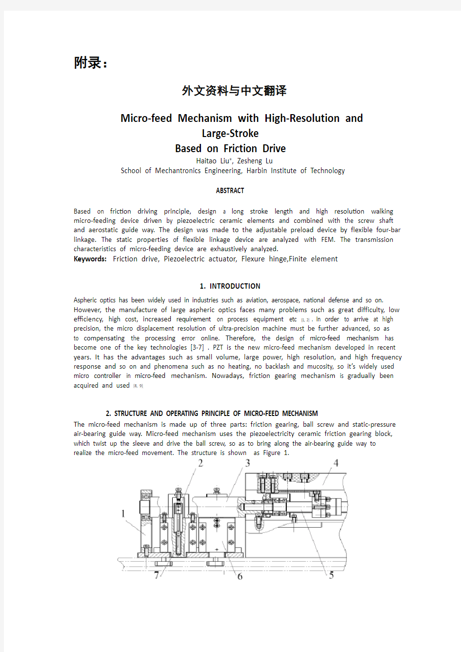
The micro-feed mechanism is made up of three parts: friction gearing, ball screw and static-pressure air-bearing guide way. Micro-feed mechanism uses the piezoelectricity ceramic friction gearing block, which twist up the sleeve and drive the ball screw, so as to bring along the air-bearing guide way to realize the micro-feed movement. The structure is shown as Figure 1.
1-Bearing bracket 2-Friction gearing block 3 Friction gearing sleeve 4-Static-pressure
air-bearing
guide way 5- Ball screw 6- Piezoelectricity ceramic base 7-Piezoelectricity ceramic used for feeding Figure 1: (a) Structure of the feed mechanism
As shown in Figure 2, the operating principle of the feed mechanism is that, friction gearing sleeve connects with ball screw, four friction gearing blocks are placed symmetrically at both sides of the sleeve. Each block is droved by the corresponding piezoelectricity ceramic used for feeding and is gripped by the corresponding gripping mechanism, which is droved by the piezoelectricity ceramic used for gripping to produce clamp force. When feeding mechanism works, the piezoelectricity ceramic used for gripping on the same side drive both the friction gearing blocks to work in certain orderliness, so as that the friction gearing sleeve turn continuously.
Figure 1: (b) Picture of the feed mechanism
Figure 2: Operating principle of the feeding mechanism
3. DESIGN OF THE ADJUSTABLE PRETIGHTENING MECHANISM
An adjustable retightening mechanism is required in the friction gearing mechanism, which must has enough pretightening force. The typical pretightening methods are plate spring pretightening mechanism, helical pretightening mechanism, and air pressure pretightening mechanism and so on. The retightening mechanism designed in this paper is flexible parallel four bars mechanism. It’s droved by piezoelectricity ceramic to supply pretightening force. The pretightening force can be changed by controlling the input voltage of piezoelectricity ceramic.
As shown in Figure 3, use the finite element software to analysis the static characteristic. When the drive force of piezoelectricity ceramic is 500N in maximum, the rigidity of flexible four bars
mechanism, analyzed by finite element software, is K=24. 1 5N/μm, and the maximum stress of flexible hinges is σ=32.7Mpa. If there is no distortion in flexible four bars mechanism (that is when the friction gearing blocks contact rigidly), the output force of piezoelectricity ceramic will completely translates to pretightening force through the flexible four bars mechanism.
4. DRIVE CHARACTERISTIC ANALYSIS OF THE MECHANISM
Studying and mastering the drive characteristic of mechanism redounds to adopting the proper measures to improve the whole performance and provides the design basis for designing the control system.
4.1 Drive torque
When system starts, there is a problem on initial inertia moment as a result of the existence of parts quality. To research the drive torque, choose the friction gearing sleeve as subject investigated. According to the theory that the kinetic energy of gearing train is same before and after conversion, the rotary inertia of each part is transformed to friction sleeve. Because of that, we can get the rotary inertia after conversion is
(a) Structure of the pretightening mechanism
(b) Node motion nephogram (c) Von-mise stress envelope
Figure 3: The static characteristic assay plan of pretightening mechanism
Where p is pitch of lead screw, m;
r is radius of the friction sleeve, m;
m S is quality of the ball screw, kg;
T is quality of the friction sleeve, kg.
Through the above analysis, we get the equivalent rotary inertia of friction sleeve. Now we choose the friction sleeve as subject investigated to discuss the drive torque (drive force)that is needed when device starts and it’s influencing factors. The following equation works when device starts:
Where J' is equivalent rotary inertia, kg·m2;
α is angular acceleration of friction sleeve, rad/s2;
r is radius of the friction sleeve, m;
M is drive torque, N·m;
F is drive force (breakout friction between friction block and friction sleeve), N.
When system starts, a condign drive deflecting couple should be applied on the friction sleeve, in order that the sleeve can have certain angular acceleration. The drive deflecting couple is generated by the output force of piezoelectricity ceramic. From equation 2 we can get that the equivalent rotary inertia of system, radius of the friction sleeve and drive force of the piezoelectricity ceramic (breakout friction between friction block and friction sleeve) are the influencing factor of mechanism start, so we should think over the influence of each factor to ensure the normal start of mechanism. Same questions exist when feed mechanism stop moving.
4.2 Driving rigidity
The driving rigidity is one of the important driving characteristics of feed mechanism. Now we will analyze the driving rigidity of feed mechanism in detail as following.
The rigidity of the feed mechanism is the cascade connection of the each segment rigidity of the feed mechanism, which has the calculated equation as follows:
Where K is the total rigidity of the feed mechanism;
K F is the touching rigidity of surface in contact between friction block and friction sleeve;
K S is the axial rigidity of lead screw;
K S' is the axial rigidity changed from the torsional rigidity of lead screw;
K N is the rigidity of nut;
K B is the rigidity of axial bearing;
K H is rigidity of nut bracket and bearing block;
K D is the axial rigidity of nut link block;
Here is the analysis and calculation of part rigidity.
4.2.1 Rigidity of the piezoelectricity ceramic
The piezoelectricity ceramic in this paper is the ceramic micro positioner typed WTYD0808055 produced by China Electronics Technology Group Corporation No.26 Research Institute. It’s rigidity measured through experiment is 15.1 5N/μm, as shown in Figure 4.
4.2.2 Touching rigidity of surface in contact between friction block and friction sleeve
Two objects contacting with each other will have certain tangential transition before relative slip in the action of tangential external force, which is called pre-displacement. The proportional relation
between force and displacement reflects a rigidity characteristic in fact [10]. The corresponding rigidity now is:
Where k is const;
N is normal pressure;
r is the radius of idealized sphere on friction surface.
It’s clear in the equation that, in special friction gearing system, k is got from experiment, r is const, the only influencing factor of touching rigidity is normal pressure N. It’s evident that the larger N is, th e larger the touching rigidity K is.
Figure 4: Rigidity curve of piezoelectricity ceramic
4.2.3 Axial rigidity changed from the torsional rigidity of lead screw
The dimension of driving chain needs to be transformed uniformly when calculating it’s rigidi ty. Therefore, the torsional rigidity must be transformed into axial rigidity as the following equation:
Where a is the rising angle of lead screw, (°);
d is th
e diameter o
f lead screw, mm;
F is the axial force of lead screw, N;
M is the input moment of lead screw, N·mm;
q is the friction angle between lead screw and nut, (°);
K T is the torsional rigidity of lead screw, N·mm/rad;
0 is the torsional deformation of lead screw, rad;
p is the lead of lead screw, mm;
G is the shear modulus of elasticity of lead screw material, Mpa;
J P is the inertia moment of cross section, mm4, J P=πd4/32;
L is the maximum distance from loading point to two thrust bearing, mm.
The axial rigidity of nut link block can be gained by the finite element analysis. The rigidity of nut
bracket and bearing
block is very large, which can be dismissed. The rigidity of other parts can be got by looking up table and calculating.
In a word, by deducing the equation of drive rigidity of feed mechanism, we have found the influencing factors of
driving rigidity caused by each driving segment, which offers the basis for further study on the driving characteristic.
5. EXPERIMENTAL STUDY OF THE
FEED MECHANISM 5.1 Foundation of the experiment
system
As shown in Figure 5, the experiment system is made up of feed mechanism, computer, piezoelectricity ceramic driver and its power supply and the inductance amesdial.
Figure 5: Foundation of experiment system
This paper uses a control method based on average curve model to set up the open loop control model. Above all, measure the experimental curve of relation between piezoelectricity ceramic control voltage and slide carriage distance. Using the Matlab software to fit the line with cubic algebraic multinomial, and the fitted line and fitted error line are as shown in Figure 6, from which we get the corresponding relational expression of control voltage and distance and therefore control the distance of feed mechanism.
a) Fitted line b) Fitted error line
Figure 6: Fit with cubic algebraic multinomial
Relational expression of control voltage and distance is as shown in equation 7:
Where x is the output distance, μm;
u is the control voltage, V.
5.2 Experimental study of system resolution
As shown in Figure 7, piezoelectricity ceramic has certain elongation. At this time, the distance of micro working table is 0.1 5μm. Then step elongating gradually on this base and keep 1.5s in each moment. The sampling time is 100ms. The resolution curve can be gained by measuring the practice distance of micro feed mechanism using the inductance amesdial.
Figure 7: Distance resolution curve of feed mechanism
6. CONCLUSION
A step micro feed mechanism with long march and high resolution was designed in this paper,
and the following conclusions were concluded:
1. Designed the pretightening mechanism based on the piezoelectricity ceramic flexible iron hinges
and analyzed its static characteristic using the finite element software;
2. Analyzed the starting torque of micro feed mechanism and calculated the equivalent rotary
inertia; analyzed the driving rigidity characteristic of micro feed mechanism and found its influencing factors;
3. The march of the micro feed mechanism can reach 300mm, and the resolution is less than 0.05μm.
REFERENCES
1. Seugng-Bok Choi, Sang-Soo Han. Position Control System Using ER Clutch and Piezoactuator. Pro. of SPIE,
2003, 5056: 424~431
2. Suzuki H, Kodera S, Mabkawa S, et al. Study on Precision Grinding of Micro a Spherical
Surface. JSPE, 1998, 64(4):61 9~623.
1. Arrasmith S. R, Kozhinova I A, Gregg L L et al. Details of The polishing Spot in
Magnetorheological Finishing(MRF).Proceedings of SPIE-the
International Society for Optical Engineering,
2001 ,Vol.3782:92~100.
2. Atherton P D, Xu Y, McConnell M. New X-Y Stage for Precision Positioning and
Scanning. SPIE, 1996, 2865:1 5~20.
3. Liu Yung -Tien, Toshiro Higuchi, Fung Rong-Fong. A Novel Precision Positioning Table Utilizing Impact Force
of Spring-Mounted Piezoelectric Actuator. Precision Engineering, 2003, 27:14221
4. Lobontiu N, Goldfarb M, Garcia E. A Piezoelectric Drive Inchworm Locomotion Device.
Mechanism and Machine Theory, 2001, 36: 425~443.
5. A. A. Elmustafa, Max G. Lagally. Flexural-hinge Guided Motion Nanopositioner Stage
for Precision Machining: Finite Element Simulations. Precision Engineering, 2001,
25: 77~8 1
6. Jaehwa Jeong, Young-Man Choi, Jun-Hee Lee. Design and Control of Dual Servo Actuator for
Near Field Optical Recording System. Pro. of SPIE, 2005, 6048: 1~8
7. Kim Jeong-Du, Nam Soo-Ryong. Development of a Micro-depth Control System for an Ultra-precision
Lathe Using a Piezoelectric Actuator. International Journal of Machine Tools and Manufacture.
Volume:37,Issue:4, April, 1997, pp.495~509
8. Li Sheng-yi, Luo Bing, Dai Yi-fan, Peng Li. Design and Experiment of The
Ultra Precision Twist-roller Friction Drive. ICAMT’99. 1999.
基于摩擦传动的高分辨率和大冲程的微量进给机械系统
哈尔滨工业大学机电工程学院刘海涛,卢泽生
摘要
在摩擦传动原理的基础上,设计了一种通过压电陶瓷结合螺杆轴和气体静压引导的方式驱动的长冲程和高分辨率的微量进给系统。设计用来使加载装置可以灵活的起落。利用有限元方法对柔性连接装置对它的静态特性进行分析。对这种微量进给系统的传输特性进行了详细的分析。
关键词:摩擦传动压电传动装置柔性铰链有限元
1.简介
光学在航空、航天、国防等领域中已得到广泛应用的行业。然而,生产的大型光学镜面面临着巨大的困难,效率较低、成本较高、增加在工艺设备的要求等。为了获得更高的精度,高微位移分辨率超-先进精密机床有待进一步深入,以补偿加工误差。因此,微量进给机制的设计已成为其关键技术之一。压电陶瓷是一种近年来发展起来的新型的微量进给机制。它所拥有的优势,比如体积小、功率大、分辨率高和高频率响应,恒温,不反弹,无粘性。因此它广泛使用在微量进给机制。如今,摩擦传动机制逐步被获得和使用。
2.微量进给机制的结构和工作原理
微量进给机制是由三个部分组成:摩擦传动装置、滚珠螺杆及静态压力空气轴承引导的方式。采用压电陶瓷微量进给机制阻滞,这些摩擦传动扭曲向上套筒和驱动器
滚珠丝杠,从而带动空气轴承引导地实现了微量进给运动。结构如图1所示。
1,轴承支架,2.活塞,3、活塞缸,4.精压力空气轴承导轨,5.滚珠丝杠,6. 压电陶瓷底座,7.压电陶瓷底座
图一:进给机构的结构
按照图2所示的进给系统工作原理是,套筒连接着球摩擦传动螺杆、四个模块是放置的两侧对称的轴套。每一块由相应的压电陶瓷用于驱动,这种机制由于是由压电陶瓷驱动,适用于夹持产生夹力。进给机制的运作,压电陶瓷适用于夹持在同一阵营的摩擦传动驱动都工作在特定块整齐,从而使摩擦传动套筒连续的传动。
图1:(b)进给系统图片
图2:进料机构的运行原理
3.结合设计的可调机制
拧紧调节机制是一个需要在摩擦传动机构,它必须有足够的预紧力。典型的方法是钢板弹簧预紧预紧机制,螺旋预紧机制,气压预紧机制等。该拧紧机制本文设计的灵活的平行四杆机构。这是由压电陶瓷droved供应预紧力。该预紧力可以改变控制的压电陶瓷输入电压。如图3所示,利用有限元软件分析的静态特性。当驱动力的压电陶瓷是在最大500N的,灵活安排四杆机构刚度,有限元分析软件,是K =24.15N/μm,以及最大应力弹性铰链是= 32.7Mpa。如果没有灵活失真四杆机构(即当摩擦传动板块跟硬性),输出力的压电陶瓷将完全转化为预紧通过灵活的四杆机构的力量。
4.驱动特性分析的机制
学习和掌握辐射源驱动特性的机制以便采取适当的措施,以改善整体性能,并提供了设计控制系统设计的基础。
4.1驱动力矩
当系统启动时,有一个初步的转动惯量作为零件的质量存在问题的结果。为了研究驱动力矩,选择摩擦传动套筒为主体的影响。根据该理论认为,动力学传动装置的能量是一样的火车前和转换后,各部分的转动惯量,转化为摩擦套。正因为如此,我们可以得到转换后的转动惯量。
图三:计划的静态特性分析结合的机制
P:导程,m
R:套筒半径,m
Ms:滚珠螺杆质量,kg
Mt:套筒质量,kg
通过以上分析,我们得到的等效转动惯量的摩擦的袖子。现在我们选择摩擦的袖子一样对象来讨论这个驱动力矩(动力),是需要装置时开始及其影响因素。下列方程装置时开始工作:
J:等效转动惯量,kg。m2
R:摩擦套筒半径,m
:套筒摩擦角加速度,rad/s2
M:驱动力矩,n。m
F:驱动力(摩擦片与套筒之间的摩擦力),n
当系统启动时,一个适宜的驱动器偏转组应该被应用于摩擦套,以使该套可以有一定的角加速度。该驱动器偏转组所产生的压电输出力陶瓷。由式2我们可以得到的等效转动惯量的系统,半径套的摩擦和驱动器对压电陶瓷(爆发摩擦块之间的摩擦和摩擦套),是影响力机制启动的因素,所以我们应该考虑各因素,以确保机制正常启动。
4.2驱动刚性
刚性的驱动是其中的重要驱动进给机构的特征之一。现在我们将分析驾驶进给机构的刚度详细的证明。不灵活的进给机构的级联连接刚度的饲料的每一个片段的机制,这种机制有计算公式如下:
K:进刀机构总体硬度
Ky:压电陶瓷刚度
Kf:接触刚度之间的接触摩擦表面的摩擦刚性块体和压电陶瓷套筒
Ks:导螺杆轴向刚度
Ks':从轴向刚度改变导螺杆的扭转刚度
Kn:螺母刚度
Kb:轴向载荷
Kh:轴承座机轴承架螺母的刚度
Kd:螺母连接块轴向刚度
这是部分的分析和计算的刚性。
4.2.1压电陶瓷刚度
本文用压电陶瓷微定位是打印的WTYD0808055陶瓷生产的中国电子科技集团公司先研究所。通过它的刚度测量实验15.15N /μm,如图4
4.2.2接触表面的接触刚度、摩擦块之间的套筒
两个物体互相接触将在以前的某些行动切向相对滑移过渡切向外部力量,这被称为预位移。力和位移之间的比例关系,实际上反映了一个刚性的特点。相应的刚性现在是:
K:常数
N:正压力
R:对摩擦半径的理想化的球体表面
很明显的,特殊摩擦方程出发,得到了齿轮传动系统、钾是由实验,r是常量,唯一的影响动人的刚性因素常压N .很明显,更大的N、较大的接触刚度K。
图4:刚度曲线的压电陶瓷
4.2.3 轴向刚度的改变,从扭转刚度的导螺杆
传动链方面的需要进行改造时统一计算它的刚性。因此,扭转刚性必须转换成下面的公式轴向刚度:
是螺旋上升的铅角,(°);
D是丝杆直径,mm;
F是丝杆轴向力,N;
M是丝杆输入时刻,N·mm;
是在丝杆和螺母之间的摩擦角,(°);
是对丝杠扭转刚度,Nmm/rad;
是丝杠扭转,rad
P是丝杆长度,mm;
G是丝杆剪切弹性模量,Mpa;
是截面惯性矩,mm
L是两个推力轴承的距离,mm
螺母连接的刚性块轴向可以得到的有限元分析。螺母支架的刚度和轴承块是非常大的,可以予以辞退。其他部分可以得到刚性通过查找表和计算。总之,通过演绎着驱动进给机构的刚性方程,我们已经找到了影响因素每一次驾驶驾驶部分,它提供了有关驾驶特性研究的基础上进一步造成刚性。
5.进刀机构的实验研究
5.1实验系统的基础
如图5所示,该实验系统是由送料机构,计算机,压电陶瓷驱动器其电源供应器及电感测微仪。
图5:基础的实验系统
本文采用一种基于平均控制曲线模型建立开环控制模型。首先,实验曲线测量压电陶瓷控制电压之间的关系和滑动运输距离。利用Matlab软件以适应线,以三次代数多项式拟合线,线拟合误差,是一样的显示在图6,由此我们得到相应的关系表达式的控制电压和距离和因
此控制距离的进给机制。
图6:适合以三次代数多项式
控制电压和距离的关系式公式7所示
x是输出的距离,μm;
u控制电压,V。
5.2实验研究系统分辨率
如图7,压电陶瓷具有一定的伸长。就在这个时候,距离工作表微0.15μm。然后一步拉伸逐渐在此基础上,保持1.5在每一时刻。采样时间是控寄存器。这分辨率曲线可以获得实践的距离,通过测量微进给机构使用的电感测微仪。
图7:距离分辨率曲线的进给机制
6.结论
微进给机构一步用长征、高分辨率的设计,并在此基础上从以下结论分析得出:
1.结合机理的基础上,设计了压电陶瓷灵活的铁铰链和分析了它静态特性,采用有限元分析软件;
2.分析了起动转矩的微进给机构的等效转动惯量计算;分析了驾驶刚度特性的微进给机构,发现其影响因素;
3. 微进给机构可以达到300mm,分辨率小于0.05μm少。
参考文献
1.Seugng-Bok Choi, Sang-Soo Han. Position Control System Using ER Clutch and Piezoactuator. Pro. of SPIE, 2003, 5056: 424~431
2.Suzuki H, Kodera S, Mabkawa S, et al. Study on Precision Grinding of Micro a Spherical Surface. JSPE, 1998, 64(4):619~623.
3.Arrasmith S. R, Kozhinova I A, Gregg L L et al. Details of The polishing Spot in Magnetorheological Finishing(MRF).Proceedings of SPIE-the International Society for OpticalEngineering,2001,Vol.3782:92~100.
4.Atherton P D, Xu Y, McConnell M. New X-Y Stage for Precision Positioning and Scanning. SPIE, 1996, 2865:15~20.
5.Liu Yung -Tien, Toshiro Higuchi, Fung Rong-Fong. A Novel Precision Positioning Table Utilizing Impact Force of Spring-Mounted Piezoelectric Actuator. Precision Engineering, 2003, 27:14221
6.Lobontiu N, Goldfarb M, Garcia E. A Piezoelectric Drive Inchworm Locomotion Device. Mechanism and Machine Theory, 2001, 36: 425~443.
7.A. A. Elmustafa, Max G. Lagally. Flexural-hinge Guided Motion Nanopositioner Stage for Precision Machining: Finite Element Simulations. Precision Engineering, 2001, 25: 77~81
8.Jaehwa Jeong, Young-Man Choi, Jun-Hee Lee. Design and Control of Dual Servo Actuator for Near Field Optical Recording System. Pro. of SPIE, 2005, 6048: 1~8
9.Kim Jeong-Du, Nam Soo-Ryong. Development of a Micro-depth Control System for an
Ultra-precision Lathe Using a Piezoelectric Actuator. International Journal of Machine Tools and Manufacture. Volume:37,Issue:4, April, 1997, pp.495~509
10.Li Sheng-yi, Luo Bing, Dai Yi-fan, Peng Li. Design and Experiment of The Ultra Precision Twist-roller Friction Drive. ICAMT'99.1999.
外文出处: 《Exploiting Software How to Break Code》By Greg Hoglund, Gary McGraw Publisher : Addison Wesley Pub Date : February 17, 2004 ISBN : 0-201-78695-8 译文标题: JDBC接口技术 译文: JDBC是一种可用于执行SQL语句的JavaAPI(ApplicationProgrammingInterface应用程序设计接口)。它由一些Java语言编写的类和界面组成。JDBC为数据库应用开发人员、数据库前台工具开发人员提供了一种标准的应用程序设计接口,使开发人员可以用纯Java语言编写完整的数据库应用程序。 一、ODBC到JDBC的发展历程 说到JDBC,很容易让人联想到另一个十分熟悉的字眼“ODBC”。它们之间有没有联系呢?如果有,那么它们之间又是怎样的关系呢? ODBC是OpenDatabaseConnectivity的英文简写。它是一种用来在相关或不相关的数据库管理系统(DBMS)中存取数据的,用C语言实现的,标准应用程序数据接口。通过ODBCAPI,应用程序可以存取保存在多种不同数据库管理系统(DBMS)中的数据,而不论每个DBMS使用了何种数据存储格式和编程接口。 1.ODBC的结构模型 ODBC的结构包括四个主要部分:应用程序接口、驱动器管理器、数据库驱动器和数据源。应用程序接口:屏蔽不同的ODBC数据库驱动器之间函数调用的差别,为用户提供统一的SQL编程接口。 驱动器管理器:为应用程序装载数据库驱动器。 数据库驱动器:实现ODBC的函数调用,提供对特定数据源的SQL请求。如果需要,数据库驱动器将修改应用程序的请求,使得请求符合相关的DBMS所支持的文法。 数据源:由用户想要存取的数据以及与它相关的操作系统、DBMS和用于访问DBMS的网络平台组成。 虽然ODBC驱动器管理器的主要目的是加载数据库驱动器,以便ODBC函数调用,但是数据库驱动器本身也执行ODBC函数调用,并与数据库相互配合。因此当应用系统发出调用与数据源进行连接时,数据库驱动器能管理通信协议。当建立起与数据源的连接时,数据库驱动器便能处理应用系统向DBMS发出的请求,对分析或发自数据源的设计进行必要的翻译,并将结果返回给应用系统。 2.JDBC的诞生 自从Java语言于1995年5月正式公布以来,Java风靡全球。出现大量的用java语言编写的程序,其中也包括数据库应用程序。由于没有一个Java语言的API,编程人员不得不在Java程序中加入C语言的ODBC函数调用。这就使很多Java的优秀特性无法充分发挥,比如平台无关性、面向对象特性等。随着越来越多的编程人员对Java语言的日益喜爱,越来越多的公司在Java程序开发上投入的精力日益增加,对java语言接口的访问数据库的API 的要求越来越强烈。也由于ODBC的有其不足之处,比如它并不容易使用,没有面向对象的特性等等,SUN公司决定开发一Java语言为接口的数据库应用程序开发接口。在JDK1.x 版本中,JDBC只是一个可选部件,到了JDK1.1公布时,SQL类包(也就是JDBCAPI)
前言 在目前激烈的市场竞争中,产品投入市场的迟早往往是成败的关键。模具是高质量、高效率的产品生产工具,模具开发周期占整个产品开发周期的主要部分。因此客户对模具开发周期要求越来越短,不少客户把模具的交货期放在第一位置,然后才是质量和价格。因此,如何在保证质量、控制成本的前提下加工模具是值得认真考虑的问题。模具加工工艺是一项先进的制造工艺,已成为重要发展方向,在航空航天、汽车、机械等各行业得到越来越广泛的应用。模具加工技术,可以提高制造业的综合效益和竞争力。研究和建立模具工艺数据库,为生产企业提供迫切需要的高速切削加工数据,对推广高速切削加工技术具有非常重要的意义。本文的主要目标就是构建一个冲压模具工艺过程,将模具制造企业在实际生产中结合刀具、工件、机床与企业自身的实际情况积累得高速切削加工实例、工艺参数和经验等数据有选择地存储到高速切削数据库中,不但可以节省大量的人力、物力、财力,而且可以指导高速加工生产实践,达到提高加工效率,降低刀具费用,获得更高的经济效益。 1.冲压的概念、特点及应用 冲压是利用安装在冲压设备(主要是压力机)上的模具对材料施加压力,使其产生分离或塑性变形,从而获得所需零件(俗称冲压或冲压件)的一种压力加工方法。冲压通常是在常温下对材料进行冷变形加工,且主要采用板料来加工成所需零件,所以也叫冷冲压或板料冲压。冲压是材料压力加工或塑性加工的主要方法之一,隶属于材料成型工程术。 冲压所使用的模具称为冲压模具,简称冲模。冲模是将材料(金属或非金属)批量加工成所需冲件的专用工具。冲模在冲压中至关重要,没有符合要求的冲模,批量冲压生产就难以进行;没有先进的冲模,先进的冲压工艺就无法实现。冲压工艺与模具、冲压设备和冲压材料构成冲压加工的三要素,只有它们相互结合才能得出冲压件。 与机械加工及塑性加工的其它方法相比,冲压加工无论在技术方面还是经济方面都具有许多独特的优点,主要表现如下; (1) 冲压加工的生产效率高,且操作方便,易于实现机械化与自动化。这是
附录 科技译文: Numerical Control Numerical Control(NC) is a method of controlling the movements of machineComponents by directly inserting coded instructions in the form of numerical data(numbers and data ) into the system.The system automatically interprets these data and converts to output signals. These signals ,in turn control various machine components ,such as turning spindles on and off ,changing tools,moving the work piece or the tools along specific paths,and turning cutting fluits on and off. In order to appreciate the importer of numerical control of machines ,let’s briefly review how a process such as machining has been carried out traditionally .After studying the working drawing of a part, the operator sets up the appropriate process parameters(such as cutting speed ,feed,depth of cut,cutting fluid ,and so on),determines the sequence of operations to be performed,clamps the work piece in a workholding device such as chuck or collet ,and proceeds to make the part .Depending on part shape and the dimensional accuracy specified ,this approach usually requires skilled
附录一英文科技文献翻译 英文原文: Experimental investigation of laser surface textured parallel thrust bearings Performance enhancements by laser surface texturing (LST) of parallel-thrust bearings is experimentally investigated. Test results are compared with a theoretical model and good correlation is found over the relevant operating conditions. A compari- son of the performance of unidirectional and bi-directional partial-LST bearings with that of a baseline, untextured bearing is presented showing the bene?ts of LST in terms of increased clearance and reduced friction. KEY WORDS: ?uid ?lm bearings, slider bearings, surface texturing 1. Introduction The classical theory of hydrodynamic lubrication yields linear (Couette) velocity distribution with zero pressure gradients between smooth parallel surfaces under steady-state sliding. This results in an unstable hydrodynamic ?lm that would collapse under any external force acting normal to the surfaces. However, experience shows that stable lubricating ?lms can develop between parallel sliding surfaces, generally because of some mechanism that relaxes one or more of the assumptions of the classical theory. A stable ?uid ?lm with su?cient load-carrying capacity in parallel sliding surfaces can be obtained, for example, with macro or micro surface structure of di?erent types. These include waviness [1] and protruding microasperities [2–4]. A good literature review on the subject can be found in Ref. [5]. More recently, laser surface texturing (LST) [6–8], as well as inlet roughening by longitudinal or transverse grooves [9] were suggested to provide load capacity in parallel sliding. The inlet roughness concept of Tonder [9] is based on ??e?ective clearance‘‘ reduction in the sliding direction and in this respect it is identical to the par- tial-LST concept described in ref. [10] for generating hydrostatic e?ect in high-pressure mechanical seals. Very recently Wang et al. [11] demonstrated experimentally a doubling of the load-carrying capacity for the surface- texture design by reactive ion etching of SiC
毕业设计(论文)外文文献翻译 文献、资料中文题目:软件开发概念和设计方法文献、资料英文题目: 文献、资料来源: 文献、资料发表(出版)日期: 院(部): 专业: 班级: 姓名: 学号: 指导教师: 翻译日期: 2017.02.14
外文资料原文 Software Development Concepts and Design Methodologies During the 1960s, ma inframes and higher level programming languages were applied to man y problems including human resource s yste ms,reservation s yste ms, and manufacturing s yste ms. Computers and software were seen as the cure all for man y bu siness issues were some times applied blindly. S yste ms sometimes failed to solve the problem for which the y were designed for man y reasons including: ?Inability to sufficiently understand complex problems ?Not sufficiently taking into account end-u ser needs, the organizational environ ment, and performance tradeoffs ?Inability to accurately estimate development time and operational costs ?Lack of framework for consistent and regular customer communications At this time, the concept of structured programming, top-down design, stepwise refinement,and modularity e merged. Structured programming is still the most dominant approach to software engineering and is still evo lving. These failures led to the concept of "software engineering" based upon the idea that an engineering-like discipl ine could be applied to software design and develop ment. Software design is a process where the software designer applies techniques and principles to produce a conceptual model that de scribes and defines a solution to a problem. In the beginning, this des ign process has not been well structured and the model does not alwa ys accurately represent the problem of software development. However,design methodologies have been evolving to accommo date changes in technolog y coupled with our increased understanding of development processes. Whereas early desig n methods addressed specific aspects of the
机械设计理论 机械设计是一门通过设计新产品或者改进老产品来满足人类需求的应用技术科学。它涉及工程技术的各个领域,主要研究产品的尺寸、形状和详细结构的基本构思,还要研究产品在制造、销售和使用等方面的问题。 进行各种机械设计工作的人员通常被称为设计人员或者机械设计工程师。机械设计是一项创造性的工作。设计工程师不仅在工作上要有创造性,还必须在机械制图、运动学、工程材料、材料力学和机械制造工艺学等方面具有深厚的基础知识。如前所诉,机械设计的目的是生产能够满足人类需求的产品。发明、发现和科技知识本身并不一定能给人类带来好处,只有当它们被应用在产品上才能产生效益。因而,应该认识到在一个特定的产品进行设计之前,必须先确定人们是否需要这种产品。 应当把机械设计看成是机械设计人员运用创造性的才能进行产品设计、系统分析和制定产品的制造工艺学的一个良机。掌握工程基础知识要比熟记一些数据和公式更为重要。仅仅使用数据和公式是不足以在一个好的设计中做出所需的全部决定的。另一方面,应该认真精确的进行所有运算。例如,即使将一个小数点的位置放错,也会使正确的设计变成错误的。 一个好的设计人员应该勇于提出新的想法,而且愿意承担一定的风险,当新的方法不适用时,就使用原来的方法。因此,设计人员必须要有耐心,因为所花费的时间和努力并不能保证带来成功。一个全新的设计,要求屏弃许多陈旧的,为人们所熟知的方法。由于许多人墨守成规,这样做并不是一件容易的事。一位机械设计师应该不断地探索改进现有的产品的方法,在此过程中应该认真选择原有的、经过验证的设计原理,将其与未经过验证的新观念结合起来。 新设计本身会有许多缺陷和未能预料的问题发生,只有当这些缺陷和问题被解决之后,才能体现出新产品的优越性。因此,一个性能优越的产品诞生的同时,也伴随着较高的风险。应该强调的是,如果设计本身不要求采用全新的方法,就没有必要仅仅为了变革的目的而采用新方法。 在设计的初始阶段,应该允许设计人员充分发挥创造性,不受各种约束。即使产生了许多不切实际的想法,也会在设计的早期,即绘制图纸之前被改正掉。只有这样,才不致于堵塞创新的思路。通常,要提出几套设计方案,然后加以比较。很有可能在最后选定的方案中,采用了某些未被接受的方案中的一些想法。
附录 INTEGRATION OF MACHINERY (From ELECTRICAL AND MACHINERY INDUSTRY)ABSTRACT Machinery was the modern science and technology development inevitable result, this article has summarized the integration of machinery technology basic outline and the development background .Summarized the domestic and foreign integration of machinery technology present situation, has analyzed the integration of machinery technology trend of development. Key word:integration of machinery ,technology,present situation ,product t,echnique of manufacture ,trend of development 0. Introduction modern science and technology unceasing development, impelled different discipline intersecting enormously with the seepage, has caused the project domain technological revolution and the transformation .In mechanical engineering domain, because the microelectronic technology and the computer technology rapid development and forms to the mechanical industry seepage the integration of machinery, caused the mechanical industry the technical structure, the product organization, the function and the constitution, the production method and the management system has had the huge change, caused the industrial production to enter into “the integration of machinery” by “the machinery electrification” for the characteristic development phase. 1. Integration of machinery outline integration of machinery is refers in the organization new owner function, the power function, in the information processing function and the control function introduces the electronic technology, unifies the system the mechanism and the computerization design and the software which constitutes always to call. The integration of machinery development also has become one to have until now own system new discipline, not only develops along with the science and technology, but also entrusts with the new content .But its basic characteristic may summarize is: The integration of machinery is embarks from the system viewpoint, synthesis community technologies and so on utilization mechanical technology, microelectronic technology, automatic control technology,
本科毕业论文(设计) 外文翻译 学院:机电工程学院 专业:机械工程及自动化 姓名:高峰 指导教师:李延胜 2011年05 月10日 教育部办公厅 Failure Analysis,Dimensional Determination And
Analysis,Applications Of Cams INTRODUCTION It is absolutely essential that a design engineer know how and why parts fail so that reliable machines that require minimum maintenance can be designed.Sometimes a failure can be serious,such as when a tire blows out on an automobile traveling at high speed.On the other hand,a failure may be no more than a nuisance.An example is the loosening of the radiator hose in an automobile cooling system.The consequence of this latter failure is usually the loss of some radiator coolant,a condition that is readily detected and corrected.The type of load a part absorbs is just as significant as the magnitude.Generally speaking,dynamic loads with direction reversals cause greater difficulty than static loads,and therefore,fatigue strength must be considered.Another concern is whether the material is ductile or brittle.For example,brittle materials are considered to be unacceptable where fatigue is involved. Many people mistakingly interpret the word failure to mean the actual breakage of a part.However,a design engineer must consider a broader understanding of what appreciable deformation occurs.A ductile material,however will deform a large amount prior to rupture.Excessive deformation,without fracture,may cause a machine to fail because the deformed part interferes with a moving second part.Therefore,a part fails(even if it has not physically broken)whenever it no longer fulfills its required function.Sometimes failure may be due to abnormal friction or vibration between two mating parts.Failure also may be due to a phenomenon called creep,which is the plastic flow of a material under load at elevated temperatures.In addition,the actual shape of a part may be responsible for failure.For example,stress concentrations due to sudden changes in contour must be taken into account.Evaluation of stress considerations is especially important when there are dynamic loads with direction reversals and the material is not very ductile. In general,the design engineer must consider all possible modes of failure,which include the following. ——Stress ——Deformation ——Wear ——Corrosion ——Vibration ——Environmental damage ——Loosening of fastening devices
外文翻译 专业机械设计制造及其自动化学生姓名刘链柱 班级机制111 学号1110101102 指导教师葛友华
外文资料名称: Design and performance evaluation of vacuum cleaners using cyclone technology 外文资料出处:Korean J. Chem. Eng., 23(6), (用外文写) 925-930 (2006) 附件: 1.外文资料翻译译文 2.外文原文
应用旋风技术真空吸尘器的设计和性能介绍 吉尔泰金,洪城铱昌,宰瑾李, 刘链柱译 摘要:旋风型分离器技术用于真空吸尘器 - 轴向进流旋风和切向进气道流旋风有效地收集粉尘和降低压力降已被实验研究。优化设计等因素作为集尘效率,压降,并切成尺寸被粒度对应于分级收集的50%的效率进行了研究。颗粒切成大小降低入口面积,体直径,减小涡取景器直径的旋风。切向入口的双流量气旋具有良好的性能考虑的350毫米汞柱的低压降和为1.5μm的质量中位直径在1米3的流量的截止尺寸。一使用切向入口的双流量旋风吸尘器示出了势是一种有效的方法,用于收集在家庭中产生的粉尘。 摘要及关键词:吸尘器; 粉尘; 旋风分离器 引言 我们这个时代的很大一部分都花在了房子,工作场所,或其他建筑,因此,室内空间应该是既舒适情绪和卫生。但室内空气中含有超过室外空气因气密性的二次污染物,毒物,食品气味。这是通过使用产生在建筑中的新材料和设备。真空吸尘器为代表的家电去除有害物质从地板到地毯所用的商用真空吸尘器房子由纸过滤,预过滤器和排气过滤器通过洁净的空气排放到大气中。虽然真空吸尘器是方便在使用中,吸入压力下降说唱空转成比例地清洗的时间,以及纸过滤器也应定期更换,由于压力下降,气味和细菌通过纸过滤器内的残留粉尘。 图1示出了大气气溶胶的粒度分布通常是双峰形,在粗颗粒(>2.0微米)模式为主要的外部来源,如风吹尘,海盐喷雾,火山,从工厂直接排放和车辆废气排放,以及那些在细颗粒模式包括燃烧或光化学反应。表1显示模式,典型的大气航空的直径和质量浓度溶胶被许多研究者测量。精细模式在0.18?0.36 在5.7到25微米尺寸范围微米尺寸范围。质量浓度为2?205微克,可直接在大气气溶胶和 3.85至36.3μg/m3柴油气溶胶。
I / 11 本科毕业设计外文翻译 <2018届) 论文题目基于WEB 的J2EE 的信息系统的方法研究 作者姓名[单击此处输入姓名] 指导教师[单击此处输入姓名] 学科(专业 > 所在学院计算机科学与技术学院 提交日期[时间 ]
基于WEB的J2EE的信息系统的方法研究 摘要:本文介绍基于工程的Java开发框架背后的概念,并介绍它如何用于IT 工程开发。因为有许多相同设计和开发工作在不同的方式下重复,而且并不总是符合最佳实践,所以许多开发框架建立了。我们已经定义了共同关注的问题和应用模式,代表有效解决办法的工具。开发框架提供:<1)从用户界面到数据集成的应用程序开发堆栈;<2)一个架构,基本环境及他们的相关技术,这些技术用来使用其他一些框架。架构定义了一个开发方法,其目的是协助客户开发工程。 关键词:J2EE 框架WEB开发 一、引言 软件工具包用来进行复杂的空间动态系统的非线性分析越来越多地使用基于Web的网络平台,以实现他们的用户界面,科学分析,分布仿真结果和科学家之间的信息交流。对于许多应用系统基于Web访问的非线性分析模拟软件成为一个重要组成部分。网络硬件和软件方面的密集技术变革[1]提供了比过去更多的自由选择机会[2]。因此,WEB平台的合理选择和发展对整个地区的非线性分析及其众多的应用程序具有越来越重要的意义。现阶段的WEB发展的特点是出现了大量的开源框架。框架将Web开发提到一个更高的水平,使基本功能的重复使用成为可能和从而提高了开发的生产力。 在某些情况下,开源框架没有提供常见问题的一个解决方案。出于这个原因,开发在开源框架的基础上建立自己的工程发展框架。本文旨在描述是一个基于Java的框架,该框架利用了开源框架并有助于开发基于Web的应用。通过分析现有的开源框架,本文提出了新的架构,基本环境及他们用来提高和利用其他一些框架的相关技术。架构定义了自己开发方法,其目的是协助客户开发和事例工程。 应用程序设计应该关注在工程中的重复利用。即使有独特的功能要求,也
机械类外文翻译 塑料注塑模具浇口优化 摘要:用单注塑模具浇口位置的优化方法,本文论述。该闸门优化设计的目的是最大限度地减少注塑件翘曲变形,翘曲,是因为对大多数注塑成型质量问题的关键,而这是受了很大的部分浇口位置。特征翘曲定义为最大位移的功能表面到表面的特征描述零件翘曲预测长度比。结合的优化与数值模拟技术,以找出最佳浇口位置,其中模拟armealing算法用于搜索最优。最后,通过实例讨论的文件,它可以得出结论,该方法是有效的。 注塑模具、浇口位臵、优化、特征翘曲变形关键词: 简介 塑料注射成型是一种广泛使用的,但非常复杂的生产的塑料产品,尤其是具有高生产的要求,严密性,以及大量的各种复杂形状的有效方法。质量ofinjection 成型零件是塑料材料,零件几何形状,模具结构和工艺条件的函数。注塑模具的一个最重要的部分主要是以下三个组件集:蛀牙,盖茨和亚军,和冷却系统。拉米夫定、Seow(2000)、金和拉米夫定(2002) 通过改变部分的尼斯达到平衡的腔壁厚度。在平衡型腔充填过程提供了一种均匀分布压力和透射电镜,可以极大地减少高温的翘曲变形的部分~但仅仅是腔平衡的一个重要影响因素的一部分。cially Espe,部分有其功能上的要求,其厚度通常不应该变化。 pointview注塑模具设计的重点是一门的大小和位臵,以及流道系统的大小和布局。大门的大小和转轮布局通常被认定为常量。相对而言,浇口位臵与水口大小布局也更加灵活,可以根据不同的零件的质量。 李和吉姆(姚开屏,1996a)称利用优化流道和尺寸来平衡多流道系统为multiple 注射系统。转轮平衡被形容为入口压力的差异为一多型腔模具用相同的蛀牙,也存
沈阳工业大学工程学院 毕业设计(论文)外文翻译 毕业设计(论文)题目:工具盒盖注塑模具设计 外文题目:Friction , Lubrication of Bearing 译文题目:轴承的摩擦与润滑 系(部):机械系 专业班级:机械设计制造及其自动化0801 学生姓名:王宝帅 指导教师:魏晓波 2010年10 月15 日
外文文献原文: Friction , Lubrication of Bearing In many of the problem thus far , the student has been asked to disregard or neglect friction . Actually , friction is present to some degree whenever two parts are in contact and move on each other. The term friction refers to the resistance of two or more parts to movement. Friction is harmful or valuable depending upon where it occurs. friction is necessary for fastening devices such as screws and rivets which depend upon friction to hold the fastener and the parts together. Belt drivers, brakes, and tires are additional applications where friction is necessary. The friction of moving parts in a machine is harmful because it reduces the mechanical advantage of the device. The heat produced by friction is lost energy because no work takes place. Also , greater power is required to overcome the increased friction. Heat is destructive in that it causes expansion. Expansion may cause a bearing or sliding surface to fit tighter. If a great enough pressure builds up because made from low temperature materials may melt. There are three types of friction which must be overcome in moving parts: (1)starting, (2)sliding, and(3)rolling. Starting friction is the friction between two solids that tend to resist movement. When two parts are at a state of rest, the surface irregularities of both parts tend to interlock and form a wedging action. To produce motion in these parts, the wedge-shaped peaks and valleys of the stationary surfaces must be made to slide out and over each other. The rougher the two surfaces, the greater is starting friction resulting from their movement . Since there is usually no fixed pattern between the peaks and valleys of two mating parts, the irregularities do not interlock once the parts are in motion but slide over each other. The friction of the two surfaces is known as sliding friction. As shown in figure ,starting friction is always greater than sliding friction . Rolling friction occurs when roller devces are subjected to tremendous stress which cause the parts to change shape or deform. Under these conditions, the material in front of a roller tends to pile up and forces the object to roll slightly uphill. This changing of shape , known as deformation, causes a movement of molecules. As a result ,heat is produced from the added energy required to keep the parts turning and overcome friction. The friction caused by the wedging action of surface irregularities can be overcome
毕业设计(论文) 外文翻译 题目西安市水源工程中的 水电站设计 专业水利水电工程 班级 学生 指导教师 2016年
研究钢弧形闸门的动态稳定性 牛志国 河海大学水利水电工程学院,中国南京,邮编210098 nzg_197901@https://www.doczj.com/doc/ad16184103.html,,niuzhiguo@https://www.doczj.com/doc/ad16184103.html, 李同春 河海大学水利水电工程学院,中国南京,邮编210098 ltchhu@https://www.doczj.com/doc/ad16184103.html, 摘要 由于钢弧形闸门的结构特征和弹力,调查对参数共振的弧形闸门的臂一直是研究领域的热点话题弧形弧形闸门的动力稳定性。在这个论文中,简化空间框架作为分析模型,根据弹性体薄壁结构的扰动方程和梁单元模型和薄壁结构的梁单元模型,动态不稳定区域的弧形闸门可以通过有限元的方法,应用有限元的方法计算动态不稳定性的主要区域的弧形弧形闸门工作。此外,结合物理和数值模型,对识别新方法的参数共振钢弧形闸门提出了调查,本文不仅是重要的改进弧形闸门的参数振动的计算方法,但也为进一步研究弧形弧形闸门结构的动态稳定性打下了坚实的基础。 简介 低举升力,没有门槽,好流型,和操作方便等优点,使钢弧形闸门已经广泛应用于水工建筑物。弧形闸门的结构特点是液压完全作用于弧形闸门,通过门叶和主大梁,所以弧形闸门臂是主要的组件确保弧形闸门安全操作。如果周期性轴向载荷作用于手臂,手臂的不稳定是在一定条件下可能发生。调查指出:在弧形闸门的20次事故中,除了极特殊的破坏情况下,弧形闸门的破坏的原因是弧形闸门臂的不稳定;此外,明显的动态作用下发生破坏。例如:张山闸,位于中国的江苏省,包括36个弧形闸门。当一个弧形闸门打开放水时,门被破坏了,而其他弧形闸门则关闭,受到静态静水压力仍然是一样的,很明显,一个动态的加载是造成的弧形闸门破坏一个主要因素。因此弧形闸门臂的动态不稳定是造成弧形闸门(特别是低水头的弧形闸门)破坏的主要原是毫无疑问。