
EM30718 Datasheet
I2C Interface Digital Proximity and Ambient Light Sensor
Version 1.01
2014-10-08
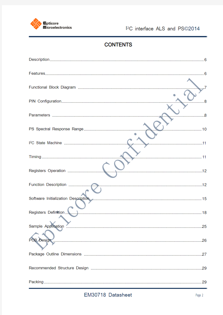
CONTENTS Description (6)
Features (6)
Functional Block Diagram (7)
PIN Configuration (8)
Parameters (8)
PS Spectral Response Range (10)
I2C State Machine (11)
Timing (11)
Registers Operation (12)
Function Description (12)
Software Initialization Description (15)
Registers Definition (18)
Sample Application (25)
PCB Design (26)
Package Outline Dimensions (27)
Recommended Structure Design (29)
Packing (29)
Recommended Reflow Profile (31)
NOTICE: (32)
FIGURE LIST
Fig. 1 EM30718 Functional Block Diagram (7)
Fig. 2 PS Spectral Response Range (10)
Fig. 3 Slave State Machine (11)
Fig. 4 Data Structure (11)
Fig. 5 Write waveform (11)
Fig. 6 Read waveform (12)
Fig. 7 Register random write operation (12)
Fig. 8 Register page write operation (12)
Fig. 9 Register random read operation (12)
Fig. 10 Sensor Operation State Machine (13)
Fig. 11 Transient Interrupt Mode Operation (14)
Fig. 12 Recommended Interrupt Procedure Flowchart (17)
Fig. 13 ALS value vs. ambient light lux (22)
Fig. 14 PS count vs. distance (cm) in different reflecting surface (The grey card is GC1890S with 18% grey) (22)
Fig. 16 Operation current vs. supply voltage (23)
Fig. 17 Normalized ALS Response vs. Angle (23)
Fig. 18 Normalized PS response vs. Angle (24)
Fig. 19 Typical Application Circuit of EM30718 (25)
Fig. 20 Typical Application Circuit of EM30718 in cases of LEDA connect to VBAT directly (26)
Fig. 21 PCB layout design guide (all linear dimensions are in mm) (27)
Fig. 22 Side view of package (27)
Fig. 23 Package Outline Dimensions (28)
Fig. 24 Recommended in case of Air gap <= 1.0mm, without rubber (29)
Fig. 25 Recommended in case of Air gap > 1.0mm, with rubber added (29)
Fig. 26 Tape & Reel Information (30)
Fig. 27 Recommended Reflow Profile for SMT (31)
TABLE LIST
Table. 1 Pin Configuration (8)
Table. 2 I2C bus timing characteristics (8)
Table. 3 Electrical Characteristics (9)
Table. 4 Optical Characteristics (9)
Table. 5 Absolute Maximum Ratings (10)
Table. 6 Registers and Register bits (18)
Table. 7 REGISTER 0x00 (RESERVED) (18)
Table. 8 REGISTER 0x01 (CONFIGURE) - PROX/ALS CONFIGURATION (18)
Table. 9 REGISTER 0x02 (INTERRUPT) - PROX/ALS INTERRUPT CONTROL (19)
Table. 10 REGISTER 0x03 (PROX_LT) - INTERRUPT LOW THRESHOLD FOR PROXIMITY SENSOR (19)
Table. 11 REGISTER 0x04 (PROX_HT) - INTERRUPT HIGH THRESHOLD FOR PROXIMITY SENSOR (19)
Table. 12 REGISTER 0x05 (ALSIR_TH1)-INTERRUPT LOW THRESHOLD FOR ALS/IR (19)
Table. 13 REGISTER 0x06 (ALSIR_TH2) INTERRUPT LOW/HIGH THRESHOLDS FOR ALS/IR (19)
Table. 14 REGISTER 0x07 (ALSIR_TH3) - INTERRUPT HIGH THRESHOLD FOR ALS/IR (20)
Table. 15 REGISTER 0x08 (PROX_DATA) - PROXIMITY SENSOR DATA (20)
Table. 16 Register 0x09 (ALSIR_DT1) - ALS/IR sensor data (Lower 8 bits) (20)
Table. 17 Register 0x0A(ALSIR_DT2) - ALS/IR sensor data(upper 4 bits) (20)
Table. 18 Register 0x0E (RESET) - Soft Reset (20)
Table. 19 Register 0x0F (OFFSET) - Offset Control of PS (21)
Table. 20 I2C Device address (21)
Table. 21 Plating Thickness (26)
Description
EM30718 is an I 2C interface sensor includes Ambient Light Sensor (ALS), Proximity Sensor (PS), and built-in LED driver. It is designed especially for smart phones and tablets with capacitive touch panel. With its ultra-low-power design, it is also useful for proximity wake-up application.
Features
● Proximity Sensor, Ambient Light Sensor, LED driver and IR LED integrated in a single Optical Module ● Wide Spectrum Response of Ambient Light Sensor (ALS)
● 50Hz/60Hz Flicker Noise Rejection
● Temperature Compensation
● Higher Sensitivity of Proximity Sensing with better SNR design ● Programmable Interrupt for PS and ALS ● Proximity Sensor (PS) Ambient Light Rejection'
● Built-In LED constant current driver high voltage tolerance up to 5.5V ● PS offset adjust for crosstalk calibration ● Enhanced PS dark surface detect flexibility ● Programmable LED driver current
● Average Current (Operation Current 95μA in low-power mode, Sleep Mode Current 0.5μA ) ● Output Type: I 2C Bus (ALS/PS) up to 400K Hz ● Operation Voltage 2.5V ~ 3.6V
● Logic Interface Voltage VBUS = 1.8V or VBUS = VDD
GND LDR LEDA
INT VDD 8LEDK 7SCL 1SDA 234
56Top View
Bottom View
Functional Block Diagram
Fig. 1 EM30718 Functional Block Diagram
PIN Configuration
I 2C State Machine
Timing
Fig. 5 Write waveform
EM30718 ALS and PS can work at the same time. ALS detects ambient light in every 100ms, and the detection value is the average of the ambient light during the period of 100 ms; PS can be set one detection in every 100 ms or 800 ms, and its LED driver current is programmable in order to meet requirements of different applications.
SCL SDA
DA TA
R
A
DATA
!A
P
Fig. 10 Sensor Operation State Machine
When both the ALS and PS are enabled, it is recommended that the software is operating in ALS Polling (Polling)/PS Interrupt (Interrupt) mode, ie. ALS register is read in every 200 ms, and main controller will adjust the backlight pulse width according to the count of ALS.
After the PS upper and lower threshold initialization is completed, PS count move from lower than low
Fig. 11 Transient Interrupt Mode Operation
Software Initialization Description
EM30718 software on initialization process is recommended as follows: WriteRegData(1, 0); //Disable and Power down
WriteRegData(2, 0); //Clear all Interrupt Flag
WriteRegData(0x0e, 0); //Initialize Reset Register
uint8 PSLT, PSHT;
PSLT = 0x40; //64 – PS Low Threshold Value
PSHT = 0x48; //72 – PS High Threshold Value
WriteRegData (3, PSLT);
WriteRegData (4, PSHT);
WriteRegData(0xf, 0x00); //Initialize PS offset
//Disable ALS Interrupt
WriteRegData (5, 0x00);
WriteRegData (6, 0xf0);
WriteRegData (7, 0xff);
if(val == 0x03) //Enable both PS & ALS{
int PSLT=0x40;
int PSHT=0x48;
i2c_smbus_write_byte_data(this_client, 0x02, 0);
i2c_smbus_write_byte_data(this_client, 0x03, PSLT);
i2c_smbus_write_byte_data(this_client, 0x04, PSHT);
i2c_smbus_write_byte_data(this_client, 0x0F, 0x00;
i2c_smbus_write_byte_data(this_client, 0x05, 0x00);
i2c_smbus_write_byte_data(this_client, 0x06, 0xF0);
i2c_smbus_write_byte_data(this_client, 0x07, 0xFF);
i2c_smbus_write_byte_data(this_client, 0x01, 0xBE);
}
else if(val& EM30718_PROXIMITY) //Enable PS only
{
int PSLT =0x40;
int PSHT=0x48;
i2c_smbus_write_byte_data(this_client, 0x03, PSLT);
i2c_smbus_write_byte_data(this_client, 0x04, PSHT);
i2c_smbus_write_byte_data(this_client, 0x0F, 0x00);
i2c_smbus_write_byte_data(this_client, 0x01, 0xB8);
}
else if(val& EM30718_ALS) //Enable ALS only
{
i2c_smbus_write_byte_data(this_client, 0x05, 0x00);
i2c_smbus_write_byte_data(this_client, 0x06, 0xF0);
i2c_smbus_write_byte_data(this_client, 0x07, 0xFF);
i2c_smbus_write_byte_data(this_client, 0x01, 0x06); }
Fig. 12 Recommended Interrupt Procedure Flowchart
Registers Definition