? Copyright 1998 Advanced Micro Devices, Inc. All Rights Reserved.
Advanced Micro Devices, Inc. (“AMD”) reserves the right to discontinue its products, or make changes in its products, at any time without notice.
The information in this publication is believed to be accurate at the time of publication, but AMD makes no representations or warranties with respect to the accuracy or completeness of the contents of this publication or the information contained herein, and reserves the right to make changes at any time, without notice. AMD disclaims responsibility for any consequences resulting from the use of the information included in this publication.
This publication neither states nor implies any representations or warranties of any kind, including but not limited to, any implied warranty of merchantability or fitness for a particular purpose. AMD’s products are not designed, intended, authorized or warranted for use as components in systems intended for surgical implant into the body, or in other applications intended to support or sustain life, or in any other application in which the failure of AMD’s product could create a situation where personal injury,
death, or severe property or environmental damage may occur. AMD assumes no liability whatsoever for claims associated with the sale or use (including the use of engineering samples) of AMD products except as provided in AMD’s Terms and Conditions of Sale for such product.Publication# 21028Rev: B Amendment/0 Issue Date: December 1998
élan?SC400 and élanSC410 Single-Chip, Low-Power,
PC/AT-Compatible Microcontrollers
DISTINCTIVE CHARACTERISTICS
élan?SC400 and élanSC410 Microcontrollers
s E86TM family of x86 embedded processors –Offers improved time-to-market, software migration, and field-proven development tools
s Highly integrated single-chip CPU with a complete set of common peripherals
–Accelerates time-to-market with simplified hardware
–Low-power 0.35-micron process technology
–Single chip delivers smallest system form factor –33-MHz, 66-MHz, and 100-MHz operating frequencies
s Am486? CPU core
–Robust Microsoft? Windows? compatible CPU –8-Kbyte write-back cache for enhanced
performance
–Fully static design with System Management Mode (SMM) for power savings
s Comprehensive power management unit –Seven modes of operation allow fine-tuning of power requirements for maximum battery life –Provides a superset of APM 1.2 features
s Glueless burst-mode
ROM/Flash memory/SRAM interface
–Reduces system cost by allowing mask ROM and Flash memory at the same time with three ROM/
Flash memory/SRAM chip selects
s Glueless DRAM controller
–Allows mixed DRAM types on a per-bank basis to reduce system cost
s VESA Local (VL) bus and ISA bus interface –Reduces time-to-market with a wide variety of off-the-shelf companion chips s Standard PC/AT system logic
(PICs, DMACs, timer, RTC)
–DOS, ROM-DOS, Windows, and industry-standard BIOS support
–Leverages the benefits of desktop computing environment at embedded price points
s Bidirectional parallel port with Enhanced Parallel Port (EPP) mode
s16550-compatible UART
s Infrared port for wireless communication –Standard and high-speed
s Keyboard interface
–Matrix keyboard support with up to 15 rows and 8 columns
–SCP-emulation mode for PC/AT and XT
keyboard support
élanSC400 Microcontroller Only
The élanSC400 microcontroller includes the following additional features designed specifically for mobile computing applications. The élanSC410 microcontrol-ler does not include these features.
s Dual PC Card (PCMCIA Version 2.1) controller supports 8- or 16-bit data bus
–End-user (after-market) system expansion
–ExCA-compliant, 82365-register set compatible –Leverages off-the-shelf card and socket services –Supports DMA transfers between I/O PC cards and system DRAM
s LCD graphics controller
–Supports monochrome and 4-bit color Super Twisted Nematic (STN) LCDs
–Unified Memory Architecture (UMA) eliminates separate video memory
2
élan?SC400 and élanSC410 Microcontrollers Data Sheet
GENERAL DESCRIPTION
The élan?SC400 and élanSC410 microcontrollers are the among the latest in a series of E86? family microcontrollers, which integrate proven x86 CPU cores with a comprehensive set of on-chip peripherals in a 0.35-micron process.
The élanSC400 and élanSC410 microcontrollers combine a 32-bit, low-voltage Am486 CPU with a complete set of PC/AT-compatible peripherals, along with the power management features required for battery operation.
Leveraging the benefits of the x86 desktop computing environment, the élanSC400 and élanSC410 microcon-trollers integrate all of the common logic and I/O func-tionality associated with a PC/AT computing system into a single device, eliminating the need for multiple periph-eral chips. Fully integrated PC/AT-compatible peripher-als include two 8259A-compatible programmable interrupt controllers (PICs), two 8237A-compatible DMA controllers, an 8254-compatible timer, a 16550 UART,an IrDA controller, VL-bus and ISA bus controllers, a real-time clock (RTC), and Enhanced Parallel Port (EPP) mode for the parallel port.
With its low-voltage Am486? CPU core and ultra-small form factor, the élanSC400 microcontroller is highly op-timized for mobile computing applications. The élanSC410 microcontroller is targeted specifically for embedded systems.
A feature comparison of the two microcontrollers is shown in Table 1 on page 3.
The élanSC400 and élanSC410 microcontrollers use the industry-standard 486 microprocessor instruction set. All software written for the x86 architecture family is compatible with the élanSC400 and élanSC410microcontrollers.
The élanSC400 and élanSC410 microcontrollers are based on a fully static design and include an advanced power management unit. Operating voltages are 2.7V–3.3 V with 5-V-tolerant I/O pads. Orderable in both 33-MHz, 66-MHz, and 100-MHz peak processor speeds, the product is available in the ultra-small 292ball grid array (BGA) package.
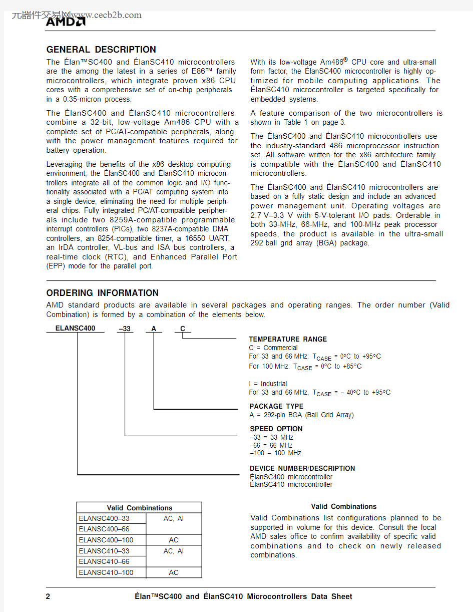
ORDERING INFORMATION
AMD standard products are available in several packages and operating ranges. The order number (Valid Combination) is formed by a combination of the elements below.
Valid Combinations
Valid Combinations list configurations planned to be supported in volume for this device. Consult the local AMD sales office to confirm availability of specific valid combinations and to check on newly released combinations.
–33
A
C
TEMPERATURE RANGE C = Commercial
For 33 and 66MHz: T CASE = 0°C to +95°C For 100MHz: T CASE = 0°C to +85°C
I = Industrial
For 33 and 66MHz, T CASE = – 40°C to +95°C PACKAGE TYPE
A = 292-pin BGA (Ball Grid Array)SPEED OPTION –33 = 33 MHz –66 = 66 MHz –100 = 100 MHz
ELANSC400
DEVICE NUMBER/DESCRIPTION élanSC400 microcontroller élanSC410 microcontroller
Valid Combinations
ELANSC400–33AC, AI
ELANSC400–66ELANSC400–100AC ELANSC410–33AC, AI ELANSC410–66ELANSC410–100
AC
élan?SC400 and élanSC410 Microcontrollers Data Sheet
3
Table 1.
Product Compari son—élanSC400 and élanSC410 Microcontrollers
Feature élanSC410élanSC400Core CPU L1 Cache
System management mode (SMM)Floating-point unit Am486 CPU 8-Kbyte Write-Back
Yes No Am486 CPU 8-Kbyte Write-Back
Yes No Data Bus 16, 32 bit 16, 32 bit ISA Interface
ISA bus mastering 8, 16 bit No 8, 16 bit No VESA Local Bus VL bus mastering 32 bit No 32 bit No Power Management Mode timers
Activity detection SMI/NMI generation Battery monitoring
Yes Yes Yes Yes Yes Yes Yes Yes Yes Yes On-Chip ROM Interface Width
Size (total ROM space)ROM chip selects Burst-mode support
Support for SRAM as ROM address space 8, 16, 32 bit 3 x 64 Mbyte
3Yes Yes 8, 16, 32 bit 3 x 64 Mbyte
3Yes Yes On-Chip DRAM Controller Banks Width
Size (total of all banks)EDO support
Support for SRAM as main memory
416, 32 bit 64 Mbyte Yes
ROM-mappable 416, 32 bit 64 Mbyte Yes
ROM-mappable Integrated PC/AT-Compatible Peripherals Programmable timer (8254-compatible)Real-time clock (146818A-compatible)Port B and Port 92h I/O registers
Cascaded DMA Controllers (8237A)Width
Total number of channels External channels
Cascaded Interrupt Controllers (8259)External IRQ signals
Yes Yes Yes 28, 16 bit
7228Yes Yes Yes 28, 16 bit 7228Bidirectional Parallel Port with EPP Mode Yes
Yes
Serial Port (UART)16550-compatible
16550-compatible Keyboard Interface
Support for external 8042 SCP XT interface
Matrix scanned with SCP emulation
Yes Yes Yes Yes Yes Yes General-Purpose Input/Output Signals 3232Infrared (IrDA) Port Yes Yes PC Card Controller Sockets
PCMCIA 2.1-compliant 82365-compatible
No
Yes 2Yes Yes LCD Graphics Controller
Programmable clock frequency Unified memory architecture (UMA)No
Yes Yes Yes JTAG Support
Yes Yes Pin Count and Package 292 BGA 292 BGA V CC : CPU core
On-chip peripheral logic
I/O tolerance (designated pins) 2.7–3.3 V 3.3 V 5 V
2.7–
3.3 V 3.3 V 5 V
Processor Clock Rate
33, 66, 100 MHz
33, 66, 100 MHz
4
élan?SC400 and élanSC410 Microcontrollers Data Sheet
Serial Port
Infrared
Graphics or
Local Bus Controller
Socket A Ctrl GPIOs or Parallel Port or PC Card Socket B
32-kHz Crystal
Clock I/O GPIOs
GPIOs
Columns or XT Keyboard DRAM Control
Addr
Addr GPIOs
GPIOs
Internal Bus
System Address Bus
Data
ROM Control Data Bus
GPIOs or
Keyboard Rows DRAM Control or Keyboard Rows ISA Control or Keyboard Rows ISA Control ISA Control or GPIOs
GPIOs Am486?
CPU
Dual DMA Controllers
8237
Power
Management
Unit
Clock Generation Real-Time Clock Boundary Scan AT Port Logic Timer 8254Dual Interrupt Controllers
8259
PC Card Controller
EPP Parallel Port UART 16550Infrared Port
Memory Management
Unit
Address Decoder
Data Steering
LCD Graphics Controller
Local Bus Controller
System Arbiter Memory Controller
Keyboard Interface:Matrix/XT/SCP
ISA Bus Controller
élanSC400 Microcontroller
élan?SC400 and élanSC410 Microcontrollers Data Sheet
5
System Arbiter
Serial Port
Infrared
Local Bus Controller
GPIOs or Parallel Port
32-kHz Crystal
Clock I/O GPIOs
GPIOs Columns or XT Keyboard DRAM Control Addr
Addr GPIOs
GPIOs
Internal Bus
System Address Bus
Data
ROM Control Data Bus
GPIOs or
Keyboard Rows DRAM Control or Keyboard Rows
ISA Control or Keyboard Rows ISA Control ISA Control or GPIOs
GPIOs
Am486?CPU
Dual DMA Controllers
8237
Power
Management
Unit
Clock Generation Real-Time Clock Boundary Scan AT Port Logic Timer 8254Dual Interrupt Controllers
8259
EPP Parallel Port
UART 16550Infrared Port
Memory Management
Unit
Address Decoder
Data Steering
Local Bus Controller
Memory Controller Keyboard Interface:Matrix/XT/SCP
ISA Bus Controller
élanSC410 Microcontroller
6
élan?SC400 and élanSC410 Microcontrollers Data Sheet
DRAM, VL, ROM, ISA and PC Card Data Scan Keyboard Rows/ISA Interface
GPIO/ISA Interface
GPIO/External Buffer Control
SA25–SA0SD15–SD0 [D31–D16]
ROMRD ROMCS1–ROMCS0
IOR IOW MEMR MEMW RSTDRV
LCDD0 [VL_RST]M [VL_BE2]LC [VL_BE1]SCK [VL_BE0]FRM [VL_LCLK]LVEE [VL_BRDY]LVDD [VL_BLAST]
DTR, RTS, SOUT CTS, DCD, DSR
RIN, SIN SIROUT SIRIN ACIN BL2–BL1BL0 [CLK_IO]GPIO_CS0GPIO_CS1
GPIO_CS2 [[DBUFRDL]]GPIO_CS3 [[DBUFRDH]]GPIO_CS4 [[DBUFOE]]GPIO_CS5 [IOCS16]
GPIO_CS6 [IOCHRDY]GPIO_CS7 [PIRQ1]GPIO_CS8 [PIRQ0]
MA11–MA5
D15–D0
RAS1–RAS0CASL/H1–CASL/H0
MWE
RST_A [[BNDSCN_TDI]]REG_A [[BNDSCN_TDO]]
CD_A RDY_A
BVD1_A, BVD2_A
WAIT_AB OE WE ICDIR
WP_A
GPIO31 [STRB] [MCEL_B] GPIO30 [AFDT] [MCEH_B] GPIO29 [SLCTIN] [RST_B] GPIO28 [INIT] [REG_B] GPIO27 [ERROR] [CD_B] GPIO26 [PE] [RDY_B] GPIO25 [ACK] [BVD1_B] GPIO24 [BUSY] [BVD2_B] GPIO23 [SLCT] [WP_B] GPIO22 [PPOEN] GPIO21 [PPDWE] 32KXTAL1, 32KXTAL2
LF_INT, LF_LS RESET BBATSEN
SPKR
BNDSCN_EN
V CC _RTC GPIO_CS9 [TC]GPIO_CS10 [AEN]GPIO_CS11 [PDACK0]LCDD1 [VL_ADS]LCDD2 [VL_W/R]
LCDD3 [VL_M/IO]LCDD4 [VL_LRDY]LCDD5 [VL_D/C]LCDD6 [VL_LDEV]LCDD7 [VL_BE3]SUS_RES / KBD_ROW14GPIO_CS12 [PDRQ0]MA4MA3 {CFG3}MA2 {CFG2}MA1 {CFG1}
MA0 {CFG0}KBD COL1-0 [XT_CLK/DATA]
KBD_ROW13 [[R32BFOE]]ROMWR
MCEL_A [[BNDSCN_TCK]]MCEH_A [[BNDSCN_TMS]]LF_VID, LF_HS
GPIO_CS13 [PCMA_VCC]GPIO_CS14 [PCMA_VPP1]GPIO15 [PCMA_VPP2]
GPIO16 [PCMB_VCC]GPIO17 [PCMB_VPP1]GPIO18 [PCMB_VPP2]
GPIO19 [LBL2]GPIO20 [CD_A2]
KBD_COL7
KBD_COL6-2 / PIRQ7-3KBD_ROW12 [MCS16]
KBD_ROW11 [SBHE]KBD_ROW10 [BALE]KBD_ROW9 [PIRQ2]KBD_ROW8 [PDRQ1]KBD_ROW7 [PDACK1]KBD_ROW6 [MA12]KBD_ROW5 [RAS3]
KBD_ROW4 [RAS2]KBD_ROW3 [CASH3]KBD_ROW2 [CASH2]KBD_ROW1 [CASL3]
KBD_ROW0 [CASL2]
LCD Graphics Controller or VESA Local Bus
8-Pin Serial Port DRAM Interface and Feature
Configuration Pins
Infrared Interface Boundary Scan Enable
Speaker RTC
Reset Loop Filters Power
Management Interface GPIOs GPIO/PC Card Power Control
Scan Keyboard Columns/IRQs/XT Keyboard Interface
Scan Keyboard Rows/DRAM Interface
VL, ROM, ISA, and PC Card Address ROM/Flash Memory Control
PC Card Command ISA Bus Command and Reset
Dedicated Single Slot PC Card and Boundary Scan Interface
Parallel Port or Second PC Card or GPIOs
32-kHz Crystal élanSC400 Microcontroller
292 BGA
Notes:
/ =Two functions available on the pin at the same time. { } = Function during hardware reset. [ ] = Alternative function selected by firmware configuration. [[ ]] = Alternate function selected by a hardware configuration pin state at power-on reset. This does not apply to [[BNDSCN_TCK]], [[BNDSCN_TMS]], [[BNDSCN_TDI]], and [[BNDSCN_TDO]]. These alternate functions are enabled by the BNDSCN_EN signal.
élan?SC400 and élanSC410 Microcontrollers Data Sheet
7
DRAM, VL, ROM, and ISA Data Scan Keyboard Rows/ISA Interface
GPIO/ISA Interface
GPIO/External Buffer Control
SA25–SA0
SD15–SD0 [D31–D16]
ROMRD ROMCS1–ROMCS0
IOR IOW MEMR MEMW RSTDRV
VL_RST VL_BE2VL_BE1VL_BE0VL_LCLK VL_BRDY VL_BLAST
DTR, RTS, SOUT CTS, DCD, DSR
RIN, SIN SIROUT SIRIN ACIN BL2–BL1BL0 [CLK_IO]GPIO_CS0GPIO_CS1
GPIO_CS2 [[DBUFRDL]]GPIO_CS3 [[DBUFRDH]]GPIO_CS4 [[DBUFOE]]GPIO_CS5 [IOCS16]
GPIO_CS6 [IOCHRDY]GPIO_CS7 [PIRQ1]GPIO_CS8 [PIRQ0]
MA11–MA5
D15–D0
RAS1–RAS0CASL/H1–CASL/H0
MWE
[[BNDSCN_TDI]][[BNDSCN_TDO]]
GPIO31 [STRB] GPIO30 [AFDT] GPIO29 [SLCTIN] GPIO28 [INIT] GPIO27 [ERROR] GPIO26 [PE] GPIO25 [ACK] GPIO24 [BUSY] GPIO23 [SLCT] GPIO22 [PPOEN] GPIO21 [PPDWE]
32KXTAL1, 32KXTAL2
LF_INT, LF_LS
RESET
BBATSEN
SPKR
BNDSCN_EN
V CC _RTC GPIO_CS9 [TC]GPIO_CS10 [AEN]GPIO_CS11 [PDACK0]VL_ADS VL_W/R
VL_M/IO VL_LRDY VL_D/C VL_LDEV VL_BE3SUS_RES / KBD_ROW14GPIO_CS12 [PDRQ0]
MA4MA3 {CFG3}
MA2MA1 {CFG1}
MA0 {CFG0}KBD COL1-0 [XT_CLK/DATA]
KBD_ROW13 [[R32BFOE]]ROMWR
[[BNDSCN_TCK]][[BNDSCN_TMS]]
LF_HS
GPIO_CS13GPIO_CS14GPIO15GPIO16GPIO17GPIO18GPIO19 [LBL2]
GPIO20
KBD_COL7
KBD_COL6-2 / PIRQ7-3KBD_ROW12 [MCS16]
KBD_ROW11 [SBHE]KBD_ROW10 [BALE]KBD_ROW9 [PIRQ2]KBD_ROW8 [PDRQ1]KBD_ROW7 [PDACK1]KBD_ROW6 [MA12]KBD_ROW5 [RAS3]
KBD_ROW4 [RAS2]KBD_ROW3 [CASH3]KBD_ROW2 [CASH2]KBD_ROW1 [CASL3]
KBD_ROW0 [CASL2]
VESA Local Bus
8-Pin Serial Port DRAM Interface and Feature
Configuration Pins
Infrared Interface Boundary Scan Enable
Speaker RTC
Reset
Loop Filters
Power
Management Interface GPIOs GPIO/
Power Control
Scan Keyboard Columns/IRQs/XT Keyboard Interface
Scan Keyboard Rows/DRAM Interface
VL, ROM, and ISA Address
ROM/Flash Memory Control
ISA Bus Command and Reset
Boundary Scan Interface
Parallel Port or GPIOs
32-kHz Crystal élanSC410 Microcontroller
292 BGA
Notes:
/{ } = Function during hardware reset. [ ] = Alternative function selected by firmware configuration. [[ ]] = Alternate function selected by a hardware configuration pin state at power-on reset. This does not apply to [[BNDSCN_TCK]], [[BNDSCN_TMS]], [[BNDSCN_TDI]], and [[BNDSCN_TDO]]. These functions are enabled by the BNDSCN_EN signal.
8
élan?SC400 and élanSC410 Microcontrollers Data Sheet
TABLE OF CONTENTS
Distinctive Characteristics ............................................................................................................1élan?SC400 and élanSC410 Microcontrollers ......................................................................1élanSC400 Microcontroller Only .............................................................................................1General Description .....................................................................................................................2Block Diagram—élanSC400 Microcontroller ..............................................................................4Block Diagram—élanSC410 Microcontroller ..............................................................................5Logic Symbol—élanSC400 Microcontroller .................................................................................6Logic Symbol—élanSC410 Microcontroller .................................................................................7Related AMD Products ..............................................................................................................12E86? Family Devices ...........................................................................................................12Related Documents ...............................................................................................................12élan?SC400 Microcontroller Evaluation Board ...................................................................13Third-Party Development Support Products ...................................................................................13Customer Service ..................................................................................................................13Architectural Overview ...............................................................................................................13Low-Voltage Am486 CPU Core ............................................................................................14Power Management ..............................................................................................................14Clock Generation ..................................................................................................................14ROM/Flash Memory Interface ...............................................................................................15DRAM Controller ...................................................................................................................15Integrated Standard PC/AT Peripherals ................................................................................15PC/AT Support Features .......................................................................................................16Bidirectional Enhanced Parallel Port (EPP) ..........................................................................16Serial Port..............................................................................................................................17Keyboard Interfaces ..............................................................................................................17Programmable General-Purpose Inputs and Outputs ...........................................................17Infrared Port for Wireless Communication ............................................................................17Dual PC Card Controller (élanSC400 Microcontroller Only) .................................................17Graphics Controller for CGA-Compatible Text and Graphics (élanSC400 Microcontroller Only) ..17JTAG Test Features ..............................................................................................................18System Interfaces .................................................................................................................18System Considerations ..............................................................................................................20Connection Diagram—élanSC400 and élanSC410 Microcontrollers ........................................24Pin Designations ........................................................................................................................25Pin Naming ............................................................................................................................25Pin Changes for the élanSC410 Microcontroller .......................................................................25Pin Designations (Pin Number)—élanSC400 Microcontroller ...................................................26Pin Designations (Pin Name)—élanSC400 Microcontroller ......................................................29Pin Designations (Pin Number)—élanSC410 Microcontroller ...................................................33Pin Designations (Pin Name)—élanSC410 Microcontroller ......................................................36Pin State Tables ........................................................................................................................40Pin Characteristics ................................................................................................................40Using the Pin State Tables ....................................................................................................41Signal Descriptions ....................................................................................................................62Multiplexed Pin Function Options ..........................................................................................70Using the Configuration Pins to Select Pin Functions............................................................74Clocking .....................................................................................................................................76Clock Generation ..................................................................................................................76Integrated Peripheral Clock Sources ....................................................................................7732-kHz Crystal Oscillator .......................................................................................................79Loop Filters ...........................................................................................................................79Intermediate and Low-Speed PLLs .......................................................................................79Graphics Dot Clock PLL (élanSC400 Microcontroller Only) . (80)
élan?SC400 and élanSC410 Microcontrollers Data Sheet
9
High-Speed PLL ....................................................................................................................81Band Gap Block ....................................................................................................................81RTC Voltage Monitor .............................................................................................................81Clock Specifications ..............................................................................................................83Absolute Maximum Ratings .......................................................................................................86Operating Ranges ......................................................................................................................86DC Characteristics Over Commercial and Industrial Operating Ranges....................................86Capacitance ...............................................................................................................................87Typical Power Numbers .............................................................................................................88Power Requirements Under Different Power Management Modes ......................................88Derating Curves .........................................................................................................................89AC Switching Characteristics and Waveforms ..........................................................................91Key to Switching Waveforms ................................................................................................91AC Switching Test Waveforms ..................................................................................................91AC Switching Characteristics over Commercial and Industrial Operating Ranges ...............92Thermal Characteristics ...........................................................................................................130Physical Dimensions—BGA 292—Plastic Ball Grid Array (131)
LIST OF FIGURES
Figure 1.Typical Mobile Terminal Design .............................................................................21Figure 2.System Diagram with Trade-offs—élanSC400 Microcontroller .............................22Figure 3.System Design with Trade-offs—élanSC410 Microcontroller ...............................23Figure 4.Clock Generation Block Diagram ...........................................................................76Figure 5.Clock Source Block Diagram .................................................................................78Figure 6.32-kHz Crystal Circuit ............................................................................................79Figure 7.32-kHz Oscillator Circuit ........................................................................................79Figure 8.Intermediate and Low-Speed PLLs Block Diagram ...............................................80Figure 9.Graphics Dot Clock PLL Block Diagram ................................................................81Figure 10.High-Speed PLL Block Diagram ............................................................................82Figure 11.RTC Voltage Monitor Circuit ..................................................................................82Figure 12.Timing Diagram for RTC-On Power-Down Sequence ...........................................83Figure 13.PLL Enabling Timing Sequence ............................................................................85Figure 14. 3.3-V I/O Drive Type A Rise Time .........................................................................89Figure 15. 3.3-V I/O Drive Type A Fall Time ...........................................................................89Figure 16. 3.3-V I/O Drive Type B Rise Time .........................................................................89Figure 17. 3.3-V I/O Drive Type B Fall Time ...........................................................................89Figure 18. 3.3-V I/O Drive Type C Rise Time .........................................................................90Figure 19. 3.3-V I/O Drive Type C Fall Time ...........................................................................90Figure 20. 3.3-V I/O Drive Type D Rise Time .........................................................................90Figure 21. 3.3-V I/O Drive Type D Fall Time ...........................................................................90Figure 22. 3.3-V I/O Drive Type E Rise Time .........................................................................90Figure 23. 3.3-V I/O Drive Type E Fall Time ...........................................................................90Figure 24.Power-Up Timing Sequence ..................................................................................92Figure 25.Fast Mode 8-/16-/32-Bit ROM/Flash Memory Read Cycle ....................................94Figure 26.Fast Mode CPU Read of Three Consecutive Bytes from 8-Bit ROM/Flash Memory ..95Figure 27.Fast Mode 8-/16-/32-Bit Flash Memory Write Cycles ............................................95Figure 28.Fast Mode 16-Bit Burst ROM Read Cycles ...........................................................96Figure 29.Fast Mode CPU Burst Read from 32-Bit Burst Mode ROM/Flash Memory ...........96Figure 30.Normal Mode 8-/16-Bit ROM/Flash Memory Read Cycles ....................................97Figure 31.Normal Mode 8-/16-Bit Flash Memory Write Cycles ..............................................97Figure 32.DRAM Page Hit Read, Interleaved ........................................................................99Figure 33.DRAM Page Hit Write, Interleaved ........................................................................99Figure 34.
DRAM Page Miss Read, Interleaved (100)
10
élan?SC400 and élanSC410 Microcontrollers Data Sheet
Figure 35.DRAM Page Hit Read, Non-Interleaved ..............................................................100Figure 36.DRAM Page Hit Write, Non-Interleaved ..............................................................101Figure 37.DRAM Page Miss Read, Non-Interleaved ...........................................................101Figure 38.EDO DRAM Page Hit Read, Non-Interleaved .....................................................102Figure 39.EDO DRAM Page Miss Read, Non-Interleaved ..................................................102Figure 40.DRAM CAS-Before-RAS Refresh ........................................................................103Figure 41.DRAM Self-Refresh .............................................................................................103Figure 42.DRAM Slow Refresh ............................................................................................104Figure 43.8-Bit ISA Bus Cycles ............................................................................................107Figure 44.16-Bit ISA Bus Cycles ..........................................................................................108Figure 45.ISA DMA Read Cycle ..........................................................................................109Figure 46.ISA DMA Write Cycle ...........................................................................................110Figure 47.VESA Local Bus Cycles .......................................................................................112Figure 48.EPP Parallel Port Write Cycle ..............................................................................114Figure 49.EPP Parallel Port Read Cycle .............................................................................115Figure 50.I/O Decode (R/W), Address Decode Only ...........................................................116Figure 51.I/O Decode (R/W), Command Qualified ..............................................................116Figure 52.I/O Decode (R/W), GPIO_CSx as 8042CS Timing ..............................................117Figure 53.Memory CS Decode (R/W), Address Decode Only .............................................117Figure 54.Memory CS Decode (R/W), Command Qualified ................................................118Figure 55.PC Card Attribute Memory Read Cycle (élanSC400 Microcontroller Only) ........120Figure 56.PC Card Attribute Memory Write Cycle (élanSC400 Microcontroller Only) .........121Figure 57.PC Card Common Memory Read Cycle (élanSC400 Microcontroller Only) .......122Figure 58.PC Card Common Memory Write Cycle (élanSC400 Microcontroller Only) .......123Figure 59.PC Card I/O Read Cycle ......................................................................................124Figure 60.PC Card I/O Write Cycle ......................................................................................125Figure 61.PC Card DMA Read Cycle (Memory Read to I/O Write) .....................................126Figure 62.PC Card DMA Write Cycle (I/O Read to Memory Write) .....................................127Figure 63.Graphics Panel Interface Timing (élanSC400 Microcontroller Only) ...................128Figure 64.
Graphics Panel Power Sequencing (élanSC400 Microcontroller Only) (129)
LIST OF TABLES
Table 1.Product Comparison—élanSC400 and élanSC410 Microcontrollers ......................3Table 2.Drive Output Description ........................................................................................40Table 3.Pin Type Abbreviations ..........................................................................................40Table 4.Power Pin Type Abbreviations ...............................................................................41Table 5.Power-Down Groups .............................................................................................41Table 6.Pin State Table—System Interface ........................................................................42Table 7.Pin State Table—Memory Interface .......................................................................44Table 8.Pin State Table—GPIOs/Parallel Port/PC Card Socket B .....................................47Table 9.Pin State Table—GPIOs/ISA Bus ..........................................................................49Table 10.Pin State Table—GPIOs/System Data (SD) Buffer Control ...................................51Table 11.Pin State Table—GPIOs ........................................................................................52Table 12.Pin State Table—Serial Port ..................................................................................52Table 13.Pin State Table—Infrared Interface .......................................................................52Table 14.Pin State Table—Keyboard Interface ....................................................................53Table 15.Pin State Table—PC Card Socket A .....................................................................55Table 16.Pin State Table—Graphics Controller/VESA Local Bus Control ............................56Table 17.Pin State Table—Miscellaneous ............................................................................58Table 18.Pin State Table—Power and Ground ....................................................................59Table 19.Signal Description Table ........................................................................................62Table 20.Multiplexed Pin Configuration Options ...................................................................70Table 21.
Pinstrap Bus Buffer Options (74)
élan?SC400 and élanSC410 Microcontrollers Data Sheet
11
Table 22.CFG0 and CFG1 Configuration .............................................................................74Table 23.CFG2 Configuration (élanSC400 microcontroller only) .........................................74Table 24.CFG3 Configuration ...............................................................................................75Table 25.BNDSCN_EN Configuration ..................................................................................75Table 26.Integrated Peripheral Clock Sources .....................................................................77Table 27.Frequency Selection Control for Graphics Dot Clock PLL .....................................80Table 28.Loop-Filter Component Specification for PLLs ......................................................84Table 29.Analog V CC (VCCA) Specification .........................................................................84Table 30.32.768-kHz Crystal Characteristics .......................................................................84Table 31.Start-Up Time Specifications PLLs ........................................................................84Table 32.PLL Jitter Specification ..........................................................................................85Table 33.Operating Voltage (Commercial and Industrial) .....................................................87Table 34.Power Estimates ....................................................................................................88Table 35.Power-On Reset Cycle ..........................................................................................92Table 36.ROM/Flash Memory Cycles ...................................................................................93Table 37.DRAM Cycles ........................................................................................................98Table 38.ISA Cycles ...........................................................................................................105Table 39.VESA Local Bus Cycles .......................................................................................111Table 40.Parallel Port Cycles .............................................................................................113Table 41.General-Purpose Input/Output Cycles .................................................................115Table 42.PC Card Cycles—élanSC400 Microcontroller Only ............................................119Table 43.PC Card Attribute Memory Read Function (élanSC400 Microcontroller Only) ....120Table 44.PC Card Attribute Memory Write Function (élanSC400 Microcontroller Only) ....121Table 45.PC Card Common Memory Read Function (élanSC400 Microcontroller Only) ..122Table 46.PC Card Common Memory Write Function (élanSC400 Microcontroller Only) ...123Table 47.PC Card I/O Read Function (élanSC400 Microcontroller Only) ..........................124Table 48.PC Card I/O Write Function (élanSC400 Microcontroller Only) ..........................125Table 49.PC Card DMA Read Function (élanSC400 Microcontroller Only) .......................126Table 50.PC Card DMA Write Function (élanSC400 Microcontroller Only) .......................127Table 51.LCD Graphics Controller Cycles—élanSC400 Microcontroller Only ...................128Table 52.Thermal Resistance ΨJ-T and θJA (°C/W) for the 292-BGA Package) .................130Table 53.
Maximum T A at Various Airflows in °C (130)
12
élan?SC400 and élanSC410 Microcontrollers Data Sheet
RELATED AMD PRODUCTS E86? Family Devices
Device Description
80C18616-bit microcontroller
80C18816-bit microcontroller with 8-bit external data bus 80L186Low-voltage, 16-bit microcontroller
80L188
Low-voltage, 16-bit microcontroller with 8-bit external data bus
Am186?EM High-performance, 80C186-compatible, 16-bit embedded microcontroller
Am188?EM High-performance, 80C188-compatible, 16-bit embedded microcontroller with 8-bit external data bus Am186EMLV High-performance, 80C186-compatible, low-voltage, 16-bit embedded microcontroller
Am188EMLV High-performance, 80C188-compatible, low-voltage, 16-bit embedded microcontroller with 8-bit
external data bus Am186ES High-performance, 80C186-compatible, 16-bit embedded microcontroller
Am188ES
High-performance, 80C188-compatible, 16-bit embedded microcontroller with 8-bit external data bus
Am186ESLV High-performance, 80C186-compatible, low-voltage, 16-bit embedded microcontroller
Am188ESLV High-performance, 80C188-compatible, low-voltage, 16-bit embedded microcontroller with 8-bit
external data bus Am186ED
High-performance, 80C186- and 80C188-compatible, 16-bit embedded microcontroller with 8- or 16-bit external data bus
Am186EDLV High-performance, 80C186- and 80C188-compatible, low-voltage, 16-bit embedded microcontroller
with 8- or 16-bit external data bus Am186ER High-performance, 80C186-compatible, low-voltage, 16-bit embedded microcontroller with 32 Kbyte of internal RAM
Am188ER High-performance, 80C188-compatible, low-voltage, 16-bit embedded microcontroller with 8-bit external data bus and 32 Kbyte of internal RAM
Am186CC High-performance, 80C186-compatible 16-bit embedded communications controller Am186CH High-performance, 80C186-compatible 16-bit embedded HDLC microcontroller Am186CU High-performance, 80C186-compatible 16-bit embedded USB microcontroller élan?SC300High-performance, highly integrated, low-voltage, 32-bit embedded microcontroller
élanSC310High-performance, single-chip, 32-bit embedded PC/AT microcontroller élanSC400Single-chip, low-power, PC/AT-compatible microcontroller élanSC410Single-chip, PC/AT-compatible microcontroller
Am386?DX High-performance, 32-bit embedded microprocessor with 32-bit external data bus Am386?SX High-performance, 32-bit embedded microprocessor with 16-bit external data bus Am486?DX
High-performance, 32-bit embedded microprocessor with 32-bit external data bus
Related Documents
The following documents provide additional information regarding the élanSC400 and élanSC410microcontrollers.
s élanSC400 and élanSC410 User’s Manual , order #21030s élanSC400 Register Set Reference Manual , order #21032s élanSC400 Register Set Reference Manual Amendment , order #21032A/1
s élanSC400 Evaluation Board User’s Manual , order #21906s élanSC400 Microcontroller and Windows CE μforCE Demonstration System User’s Manual ,order #21892s ROMCS0 Redirection to PC Card Socket A on the élanSC400 Microcontroller Application Note , order #21643
élan?SC400 and élanSC410 Microcontrollers Data Sheet
13
élan ?SC400 Microcontroller Evaluation Board
The élan?SC400 microcontroller evaluation board is a stand-alone evaluation platform for the élanSC400 and élanSC410 microcontrollers.
As a test and development platform for designs based on the élanSC400 and élanSC410 microcontrollers,this AMD product is used by system designers to ex-periment with design trade-offs, make power measure-ments, and develop software. Contact your local AMD sales office for more information on evaluation board availability and pricing.
Third-Party Development Support Products
The FusionE86S M Program of Partnerships for Application Solutions provides the customer with an array of products designed to meet critical time-to-market needs. Products and solutions available from the AMD FusionE86 partners include protocol stacks,emulators, hardware and software debuggers, board-level products, and software development tools,among others.
In addition, mature development tools and applications for the x86 platform are widely available in the general marketplace.
Customer Service
The AMD customer service network includes U.S.offices, international offices, and a customer training center. Expert technical assistance is available from the AMD worldwide staff of field application engineers and factory support staff to answer E86? and C o m m 86? fa m i l y ha r d w ar e a n d s o f tw ar e development questions.
Hotline and World Wide Web Support
For answers to technical questions, AMD provides e-mail support as well as a toll-free number for direct access to our corporate applications hotline.
The AMD World Wide Web home page provides the latest product information, including technical information and data on upcoming product releases. In addition, EPD CodeKit software on the Web site provides tested source code example applications.Additional contact information is listed on the back of this datasheet. For technical support questions on all E86 an d Com m86 pr odu cts , s end e-mai l t o epd.support@https://www.doczj.com/doc/af10703698.html, .
World Wide Web Home Page
To access the AMD home page, go to: https://www.doczj.com/doc/af10703698.html, .Then follow the Embedded Processors link for information about E86 and Comm86 products.Questions, requests, and input concerning AMD’s W W W pa g e s c a n be s e nt v i a e -m a il t o webmaster@https://www.doczj.com/doc/af10703698.html, .Documentation and Literature
Free information such as data books, user’s manuals,data sheets, application notes, the E86? Family Products and Development Tools CD , order #21058,and other literature is available with a simple phone call. Internationally, contact your local AMD sales office for product literature. Additional contact information is listed on the back of this data sheet.ARCHITECTURAL OVERVIEW
The architectural goals of the élanSC400 and élanSC410 microcontrollers included a focus on CPU performance, CPU-to-memory performance, and inter-nal graphics controller (élanSC400 microcontroller only) performance. The resulting architecture includes several distinguishing features of interest to the system designer:
s The main system DRAM is shared between the CPU and graphics controller, so that the graphics controller can be serviced quickly to maintain video display performance at higher panel resolutions.The internal unified memory architecture (UMA)implemented on the élanSC400 and élanSC410microcontrollers means lower cost and less complication for the system designer, with only one DRAM interface, fewer pins, and a much smaller board for many designs.s CPU-to-memory performance is critical for both DRAM and ROM accesses. The CPU on the élanSC400 microcontroller has a concurrent path to the ROM/Flash memory interface and can execute code out of ROM/Flash memory at the same time as the graphics controller is accessing DRAM for a screen refresh. Many system designs can take advantage of this concurrency without sacrificing performance.
Corporate Applications Hotline (800) 222-9323Toll-free for U.S. and Canada 44-(0) 1276-803-299
U.K. and Europe hotline
Literature Ordering (800) 222-9323Toll-free for U.S. and Canada (512) 602-5651Direct dial worldwide (512) 602-7639
Fax
14
élan?SC400 and élanSC410 Microcontrollers Data Sheet
s The ROM/Flash memory interface provides the flex-ibility to optimize the performance of ROM cycles,including the support of burst-mode ROMs. This is beneficial because products based on the élanSC400 and élanSC410 microcontrollers may be implemented such that the operating system or application programs are executed from ROM.s Because the microcontrollers support a large num-ber of external buses and interfaces, the address and data buses are shared between the various in-terfaces to reduce pin count on the chip.These features result in a versatile architecture that can use various combinations of data bus sizes to achieve cost and performance goals. The architecture provides maximum performance and flexibility for high-end vertical applications, but contains functionality for a wider horizontal market that may demand less performance.
s A typical lower performance/lower cost system might implement 16-bit DRAM banks, an 8-bit ISA bus, an 8/16-bit PC Card bus, and use the internal graphic controller.s A higher performance, full-featured system might include 32-bit DRAM, VL-bus to an external graph-ics controller, and a 16-bit ISA/PC Card bus.The following basic data bus configuration rules apply.(A complete list of feature trade-offs to be considered in system design can be found in “System Consider-ations” on page 20.)
s When the internal graphics controller on the élanSC400 microcontroller is enabled, DRAM is al-ways 16 bits wide, and no 32-bit targets are sup-ported. This is because the graphics controller needs a guaranteed short latency for adequate video performance. If either 32-bit DRAMs, 32-bit ROMs, or the VL-bus is enabled, the internal graph-ics controller is unavailable. Note that, as a derivative of the original élanSC400 mi-crocontroller, the élanSC410 microcontroller shares the primary architectural characteristics of the élanSC400 microcontroller described above, minus the graphics controller and PCMCIA interfaces.The following sections provide an overview of the fea-tures of the élanSC400 and élanSC410 microcontrollers,including on-chip peripherals and system interfaces.
Low-Voltage Am486 CPU Core
The élanSC400 and élanSC410 microcontrollers are based on the low-voltage Am486 CPU core. The core includes the following features:
s 2.7–3.3-V operation reduces power consumption s Industry-standard 8-Kbyte unified code and data write-back cache improves both CPU and total sys-
tem performance by significantly reducing traffic on the DRAM bus.
s System management mode (SMM) facilitates de-signs requiring power management by providing a mechanism to control power to unneeded peripher-als transparently to application software.To reduce power consumption, the floating-point unit has been removed from the Am486 CPU core. Float-ing-point instructions are not supported on the élanSC400 and élanSC410 microcontrollers, although normal software emulation can be easily implemented.The élanSC400 and élanSC410 microcontrollers use the industry-standard 486 instruction set. Software written for the 486 microprocessor and previous mem-bers of the x86 architecture family can run on the élanSC400 and élanSC410 microcontrollers.
Power Management
Power managem ent o n th e élanS C400 and élanSC410 microcontrollers includes a dedicated power management unit and additional power man-agement features built into each integrated peripheral.The élanSC400 and élanSC410 microcontrollers can use the following techniques to conserve power:s Slow down clocks when the system is not in active use s Shut off clocks to parts of the chip that are idle s Switch off power to parts of the system that are idle s Automatically reduce power use when batteries are low The power management unit (PMU) controls stopping and changing clocks, SMI generation, timers, activities,and battery-level monitoring. It provides:
s Hyper-Speed, High-Speed, Low-Speed, Temporary Low-Speed, Standby, Suspend, and Critical Suspend modes s Dynamically adjusted clock speeds for power reduction s Programmable activity and wake-up monitoring s General-purpose I/O signals to control external devices and external power management s Battery low and AC power monitoring s SMI/NMI synchronization and generation
Clock Generation
The élanSC400 and élanSC410 microcontrollers re-quire only one 32.768-kHz crystal to generate all the other clock frequencies required by the system. The output of the on-chip crystal oscillator circuit is used to generate the various frequencies by utilizing four Phase-Locked Loop (PLL) circuits (three for the élanSC410 microcontroller). An additional PLL in the CPU is used for Hyper-Speed mode.
élan?SC400 and élanSC410 Microcontrollers Data Sheet
15
ROM/Flash Memory Interface
The integrated ROM/Flash memory interface supports the following features:
s 8-, 16-, and 32-bit ROM/Flash memory interfaces s Three ROM/Flash memory chip selects s Burst-mode ROMs
s ROM accesses at both ISA and CPU speeds (normal and fast-speed modes)s Dedicated ROM Read and ROM Write signals for better performance Each ROM space can accommodate up to 64 Mbyte of ROM. The three ROM spaces can be individually write-protected. This is useful for protecting code residing in Flash memory devices.
Two of the three ROM/Flash memory chip selects can be remapped to a PC Card socket via pinstrap or soft-ware control. This feature supports reprogramming of soldered-down Flash memory boot devices and also simplifies testing of BIOS/XIP OS code.
Three ROM access modes are supported: Normal mode, Fast mode, and Burst mode. A different set of timings is used in each mode. In Normal ROM access mode, the bus cycles follow ISA-like timings. In Fast ROM access mode, the bus cycle timing occurs at the CPU clock rate with controls for wait-state insertion.Burst ROM access timing is used when the ROM/Flash memory interface is fulfilling an internal CPU burst re-quest to support a cache line refill.
Wait states are supported for all ROM and Flash mem-ory accesses, including Burst mode. Burst-mode (page-mode) ROM reads are supported for either a 16-or 32-bit ROM interface running in Fast mode.
DRAM Controller
The integrated DRAM controller provides the signals and associated timing necessary to support an external DRAM array with minimal software programming and overhead. Internal programmable registers are provided to select the DRAM type and operating mode, as well as refresh options. A wide variety of commodity DRAMs are supported, and substantial flexibility is built into the DRAM controller to optimize performance of the CPU and (on the élanSC400 microcontroller) the internal graphics control-ler, which uses system DRAM for its buffers.
The DRAM controller supports the following features:s 3.3-V, 70-ns DRAMs s Up to four banks s 16-bit or 32-bit banks
s Up to 64 Mbyte of total memory s Self-refresh DRAMs
s Fast page and Extended Data Out (EDO) DRAMs s Two-way interleaved operation among identically populated banks using fast-page mode devices s Mixed depth and width of DRAM banks in non-inter-leaved mode s Symmetrical and asymmetrical DRAM support
Integrated Standard PC/AT Peripherals
The élanSC400 and élanSC410 microcontrollers in-clude all the standard peripheral controllers that make up a PC/AT system.Dual DMA Controllers
Dual, cascaded, 8237A-compatible DMA controllers provide seven user-definable DMA channels. Of the seven internal channels, four are 8-bit channels and three are 16-bit channels. Channel 4 is used for the cas-cade function.
Any two of the seven channels can be mapped simul-taneously to external DMA request/acknowledge lines.The DMA controller on the élanSC400 and élanSC410microcontrollers is software compatible with the PC/AT cascaded 8237 controller pair. Its features include:s Single, block, and demand transfer modes s Enable/disable channel controller s Address increment or decrement s Software priority
s 64-Mbyte system address space for increased performance s Dynamic clock-enable design for reducing clocked elements during DMA inactivity s Programmable clock frequency for performance Dual Interrupt Controllers
Dual, cascaded, 8259-compatible programmable interrupt controllers support 15 user-definable interrupt levels. Eight external interrupt requests can be mapped to any of the 15 internal IRQ inputs.
The interrupt controller block includes these features:s Software-compatibility with PC/AT interrupt controllers s 15-level priority controller s Programmable interrupt modes
s Individual interrupt request mask capability s Accepts requests from peripherals
s Resolves priority on pending interrupts and interrupts in service s Issues interrupt request to processor
s Provides interrupt vectors for interrupt service routines s Tied into the PMU for power management
16
élan?SC400 and élanSC410 Microcontrollers Data Sheet
The interrupt controller block is functionally compatible with the standard cascaded 8259A controller pair as implemented in the PC/AT system. The master control-ler drives the CPU’s interrupt input signal based on the highest priority interrupt request pending at the master controller’s IRQ7–IRQ0 inputs. The master IRQ2 input is configured for Cascade mode and is driven only by the slave controller’s interrupt output signal. The high-est pending interrupt at the slave’s IRQ inputs will therefore drive the IRQ2 input of the master.
The interrupt controller has programmable sources for interrupts that are controlled through extended config-uration registers and, on the élanSC400 microcontrol-ler, through PC Card controller configuration registers.Programmable Interval Timer (PIT)
The programmable interval timer (PIT) on the élanSC400 and élanSC410 microcontrollers is soft-ware-compatible with PC/AT 8254 system timers. The PIT provides three 16-bit counters that can be operated independently in six different modes. The PIT is gener-ally used for timing external events, counting, and pro-ducing repetitive waveforms. The PIT can be programmed to count in binary or in BCD.Real-Time Clock (RTC)
The RT C designed into the élanSC400 and élanSC410 microcontrollers is compatible with the MC146818A device used in PC/AT systems. The RTC consists of a time-of-day clock with alarm interrupt and a 100-year calendar. The clock/calendar has a pro-grammable periodic interrupt, 114 bytes of static user RAM, and can be represented in either binary or BCD.The RTC includes the following features:
s Counts seconds, minutes, and hours of the day s Counts days of the week, date, month, and year s 12–24 hour clock with AM and PM indication in 12-hour mode s 14 clock, status, and control registers s 114 bytes of general-purpose RAM
s Three separately software-maskable and testable interrupts –Time-of-day alarm is programmable to occur from once-per-second to once-per-day –Periodic interrupts can be continued to occur at rates from 122 μs to 500 ms –Update-ended interrupt provides cycle status s Dedicated power pin directly supports lithium backup battery when the rest of the chip is com-pletely powered down (RTC-only mode)
s Voltage monitor circuit checks the voltage level of the lithium backup battery and sets a bit when the battery is below specification.s Internal RTC reset signal performs a reset when power is applied to the RTC core.
PC/AT Support Features
The élanSC400 and élanSC410 microcontrollers provide all of the support functions found in the original IBM PC/AT. These include the Port B status and control bits, speaker control, CPU-core reset based on the system control processor (SCP), and A20 gate control,as well as extensions for fast CPU core reset. In addition, a CPU shutdown cycle (e.g., as a result of a triple fault) generates a CPU core reset.
Bidirectional Enhanced Parallel Port (EPP)
The parallel port on the élanSC400 and élanSC410microcontrollers is functionally compatible with IBM PC/AT and PS/2 systems, with an added EPP mode for faster transfers. The microcontroller’s parallel port in-terface provides all the status inputs, control outputs,and the control signals necessary for the external par-allel port data buffers.
The parallel port interface on both microcontrollers is shared with some of the GPIO signals and, on the élanSC400 microcontroller, with the second PC Card socket interface. Only one of these interfaces can be enabled at one time.
The parallel port interface can be configured to operate in one of three different modes of operation:
s PC/AT Compatible mode : This mode provides a byte-wide forward (host-to-peripheral) channel with data and status lines used according to their original (Centronics) definitions in the IBM PC/AT.s Bidirectional mode : This mode offers byte-wide bi-directional parallel data transfers between host and peripheral, equivalent to the parallel interface on the IBM PS/2.s Enhanced Parallel Port (EPP) mode : This mode provides a byte-wide bidirectional channel con-trolled by the microcontroller. It provides separate address and data cycles over the eight data lines of the interface with an automatic address and data strobe for the address and data cycles, respectively.EPP mode offers wider system bandwidth and in-creased performance over both the PC/AT Compat-ible and Bidirectional modes.
élan?SC400 and élanSC410 Microcontrollers Data Sheet
17
Serial Port
The élanSC400 and élanSC410 microcontrollers in-clude an industry-standard 16550A UART. The UART can be used to drive a standard 8-pin serial interface or a 2-pin infrared interface. The serial interface and infra-red interface signals are available on the élanSC400and élanSC410 microcontrollers at all times, though only one is available at any given time.
The UART powers up as a 16450-compatible device. It can be switched to and from the FIFO (16550) mode under software control. In the FIFO mode, the receive and the transmit circuitry are each enhanced by sepa-rate 16-byte FIFOs to off-load the CPU from repetitive service routines.
The serial port includes the following features:s Eight-pin interface: serial in, serial out, two modem control lines, and four modem status lines s Separately enabled receiver line status, receiver data, character timeout, transmitter holding register,and modem status interrupts s Baud-rate generator provides input clock divisor from 1 to 65535 to create 16x clock s 5-, 6-, 7-, or 8-bit data
s Even, odd, stick, or no parity generation and checking s 1, 1-1/2 or 2 stop-bit generation s Break generation/detection
Keyboard Interfaces
The integrated keyboard controller has the following features:
s Matrix keyboard support with up to 15 rows and 8columns s Hardware support for software emulation of the System Control Processor (SCP) emulation logic s XT keyboard interface
Programmable General-Purpose Inputs and Outputs
The chip supports several general-purpose I/O signals (GPIOs) that can be used on the system board. There are two classifications of GPIO available: the GPIOx signals, which are programmable as inputs or outputs only, and the GPIO_CSx signals.
The GPIO_CSx signals have many programmable op-tions. They can be configured as chip selects. As out-puts, these signals are individually programmable to be High or Low for the following PMU modes: Hyper, High-Speed, Low-Speed, Standby, and Suspend. As inputs,they can be programmed to cause System Manage-ment Interrupts (SMIs), Non-Maskable Interrupts
(NMIs), wake-ups, or activities for the power manage-ment unit. They can also be used as I/O or memory chip selects.
Infrared Port for Wireless Communication
The élanSC400 and élanSC410 microcontrollers sup-port infrared data transfer. This support consists of adding additional transmit and receive serializers as well as a controlling state machine and DMA interface to the internal UART.
The integrated infrared port includes these features:s Low-speed mode supports all bit rates from UART,up to 115 Kbit/s s High-speed mode transfers 1.152 Mbit/s using DMA
Dual PC Card Controller
(élanSC400 Microcontroller Only)
The PC Card host bus adapter included on the élanSC400 microcontroller conforms to PCMCIA Stan-dard Release 2.1. It provides support for two sockets,each implementing the PC Card memory and I/O inter-faces. The PC Card controller is not supported on the élanSC410 microcontroller.
The PC Card controller includes the following features:s ExCA-compliant, 82365-register-set compatible s 8-bit and 16-bit data bus
s DMA transfers between I/O PC cards and system DRAM s Ten available memory windows, five per socket Of the two PC Card sockets supported, only one is available in all modes of operation. The second socket is multiplexed with the parallel port and GPIO features.Register set compatibility with the 82365SL PC Card Interface Controller is maintained where features are common to both controllers.
Of the ten memory windows available, six are dedi-cated to the PC Card controller and four are shared with memory mapping system (MMS) Windows C–F.Two of the three ROM/Flash memory chip selects can be remapped to a PC Card socket via pinstrap or soft-ware control. This feature supports reprogramming of soldered down Flash memory boot devices and also simplifies testing of BIOS/XIP OS code.
Graphics Controller for CGA-Compatible Text and Graphics
(élanSC400 Microcontroller Only)
The graphics controller included on the élanSC400 mi-crocontroller offers a low-cost integrated graphics solu-tion for the mobile terminal market. Integration with the main processor and system logic affords the advan-
18
élan?SC400 and élanSC410 Microcontrollers Data Sheet
tages of an integrated local-bus interface and frame and font buffers that are shared with main memory. The graphics controller is not supported on the élanSC410microcontroller.
The graphics controller includes the following features:s Supports multiple panel resolutions
s Provides internal unified memory architecture (UMA) with optional write-through caching of graphics buffers s Stores frame and font buffer data in system DRAM,eliminates extra memory chip s Provides software compatibility with Color Graphics Adapter (CGA), Monochrome Display Adapter (MDA), and Hercules Graphics Adapter (HGA) text and graphics s Supports single-scan or dual-scan monochrome LCD panels with 4-bit or 8-bit data interface s Typical panels supported include:
–640x 200, 640x 240, 640x 480, 480x 320,480x 240, 480x 128, 320x 200, 320x 240–Other resolutions can be supported
s Supports single-scan color STN panels with 8-bit interface, same resolutions as monochrome mode s Internal local-bus interface provides high perfor-mance s Logical screen can be larger than physical window. s Supports panning and scrolling
s Supports horizontal dot doubling and vertical line doubling The following MDA/CGA-compatible text mode fea-tures are supported:
s 40, 64, or 80 columns with characters 16, 10, or 8pixels wide s Variable height characters up to 32 lines s Variable width characters—8, 10, or 16 pixels s MDA Monochrome, or CGA 4 gray shades, 16 gray shades, or 16-colors s 16-Kbyte downloadable font area, relocatable on 16-Kbyte boundaries within lower 16 Mbytes of system DRAM (can be write protected)s 16-Kbyte frame buffer, relocatable on either 16-Kbyte boundaries within lower 16 Mbyte of system DRAM (CGA-compatible mode) or 32-Kbyte boundaries when the frame buffer is larger than 16Kbyte (flat-mapped mode)
The following graphics mode features are supported:s 640x 200 1 bit-per-pixel, CGA-compatible graphics buffer memory map s 320x 200 2 bits-per-pixel, CGA-compatible graph-ics buffer memory map s 640x 480 2 bits-per-pixel, flat memory map (lower resolutions supported)s 640x 480 1 bit-per-pixel, flat memory map s 1, 2, or 4 bits-per-pixel packed-pixel flat-mapped graphics up to 640x 240/480x 320 with two map-ping modes:–16-Kbyte window with bank swapping to ad-dress up to 64 Kbyte of graphics frame buffer while consuming only 16 Kbyte of DOS/Real-mode CPU address space –Direct-mapped (no bank swapping) with locat-able base address, up to 128-Kbyte direct ad-dressability s Hercules Graphics mode emulation (HGA)
JTAG Test Features
The élanSC400 and élanSC410 microcontrollers pro-vide a boundary-scan interface based on the IEEE Std 1149.1, Standard Test Access Port and Boundary-Scan Architecture . The test access port provides a scan interface for testing the microcontroller and sys-tem hardware in a production environment. It contains extensions that allow a hardware-development system to control and observe the microcontroller without inter-posing hardware between the microcontroller and the system.
System Interfaces
Data Buses
The élanSC400 and élanSC410 microcontrollers pro-vide 32 bits of data that are divided into two separate 16-bit buses.
s System Data Bus : The system (or peripheral) data bus (SD15–SD0) is always 16 bits wide and is shared between ISA, 8-bit or 16-bit ROM/Flash memory, and PC Card peripherals (élanSC400microcontroller only). It can be directly connected to all of these devices. In addition, these signals are the upper word of the VESA local (VL) data bus, the 32-bit DRAM interface, and the 32-bit ROM interface.s Data Bus : The D15–D0 data bus is used during 16-bit DRAM cycles. For 32-bit DRAM, VL-bus, and ROM cycles, this bus is combined with the system data bus. In other words, the data bus signals (D31–D16) are shared with the system data bus signals SD15–SD0.
élan?SC400 and élanSC410 Microcontrollers Data Sheet
19
The élanSC400 and élanSC410 microcontrollers sup-port the data bus configurations listed below. External transceivers or buffers can be used to isolate the buses.
s 16-bit DRAM bus, 8-/16-bit ROM, 32-bit VL-bus disabled, internal graphics controller enabled/disabled s 16-/32-bit DRAM bus, 8/16-bit ROM, 32-bit VL-bus enabled/disabled, internal graphics controller disabled s 16-/32-bit DRAM bus, 32-bit ROM, 32-bit VL-bus enabled/disabled, internal graphics controller disabled See Figure 2 on page 22 and Figure 3 on page 23 for block diagrams of example systems.
The élanSC400 and élanSC410 microcontrollers offer flexibility in configuring the ROM and DRAM data buses for different widths. The widths (8/16/32 bits) for ROMCS0 are programmed during power-up through two pinstraps, CFG0 and CFG1. The DRAM widths (16/32 bits) are programmed through configuration registers. Up to four 16- or 32-bit banks of DRAM are supported.
Two of the three ROM/Flash memory chip selects (ROMCS2–ROMCS0) can be remapped to a PC Card socket via pinstrap or software control. This feature supports reprogramming of soldered-down Flash memory boot devices and also simplifies testing of BIOS/XIP (execute in place) OS code.Address Buses
There are two external address buses on the élanSC400 and élanSC410 microcontrollers.
s System Address Bus : The SA25–SA0 system ad-dress bus outputs the physical memory or I/O port latched addresses. These addresses are used by all external peripheral devices other than main sys-tem DRAM. In addition, the system address bus is the local address bus in VL-bus mode.s DRAM Address Bus : DRAM row and column ad-dresses are multiplexed onto the DRAM address bus (MA12–MA0). Row addresses are driven onto this bus and are valid upon the falling edge of RAS.Column addresses are driven onto this bus and are valid upon the falling edge of CAS.The SA bus is shared between the ISA bus, the VL-bus, the ROM/Flash memory controller and, on the élanSC400 microcontroller, the PC Card controller.The élanSC400 and élanSC410 microcontrollers provide programmable drive strengths in the I/O buffers to accommodate loading for various system configurations.
Memory Management
The élanSC400 and élanSC410 microcontrollers man-age up to nine separate physical device memory ad-dress spaces. All but the ISA memory address space can have a depth of up to 64 Mbyte each. The ISA bus memory area is limited to 16 Mbyte, as defined by ISA specifications. The microcontroller will drive all 26 ad-dress lines on ISA cycles to allow up to 64-Mbyte ad-dress space, as described in the memory management section of the élanSC400 and élanSC410 Microcon-trollers User’s Manual (order #21030)—refer to the subsection on ISA bus addressing). The nine memory spaces are:
s System memory address space (DRAM)s ROM0 memory address space (ROMCS0 signal)s ROM1 memory address space (ROMCS1 signal)s ROM2 memory address space (ROMCS2 signal)s PC Card Socket A memory address spaces (com-mon and attribute) (élanSC400 microcontroller only)s PC Card Socket B memory address spaces (com-mon and attribute) (élanSC400 microcontroller only)s External ISA/VL-bus memory address space The system memory address space (DRAM) is acces-sible using direct-mapped CPU addresses and can also be accessed by the CPU in an indirect method using the Memory Mapping System (MMS). On the élanSC400 microcontroller, DRAM is also accessible by the integrated graphics controller if enabled.The ROM0 address space is partially accessible via a direct mapping of the CPU address bus and partially accessible via the MMS. The ROM1 and ROM2address spaces are only accessible indirectly using the MMS.
On the élanSC400 microcontroller, the PC Card ad-dress spaces are accessed through a separate,82365SL-compatible address mapping system.The ISA/VL-bus address space is accessible as a direct mapping of the CPU address bus. ISA memory cycles are generated when the CPU generates a memory cycle that is not detected as an access to any other memory space. An ISA bus memory cycle can also be generated if the CPU generates a memory address that resides in the ISA overlapping memory region window. This window can be defined to overlay any system memory region below 16 Mbyte.
20
élan?SC400 and élanSC410 Microcontrollers Data Sheet
ISA Bus Interface For External ISA Peripherals The ISA interface consists of a subset of ISA-compati-ble bus signals, allowing for the connection of 8- or 16-bit devices supporting ISA-compatible I/O, memory,and DMA cycles. The following features are supported:s 8.2944-MHz maximum bus clock speed s Programmable DMA clock speed up to 16 MHz s 8-bit and 16-bit ISA I/O and memory cycles (ISA memory is non-cacheable)s Direct connection to 3- or 5-volt peripherals Eight programmable IRQ input signals are available.These interrupts can be routed via software to any available PC/AT-compatible interrupt channel. Two programmable DMA channels are available for ex-ternal DMA peripherals. These DMA channels can be routed to software to any available ISA DMA channel. VESA Local (VL) Bus Interface Supports 32-Bit Memory and I/O Targets
The VESA local (VL) bus controller provides the sig-nals and associated timing necessary to support a sin-gle VESA compliant VL-bus target. Multiple VL-bus targets can be supported using external circuitry to allow multiple VL devices to share the VL_LDEV sig-nal. This allows the élanSC400 and élanSC410 micro-controllers to operate as a normal VL-bus motherboard controller, in accordance with the VL-Bus Standard 2.0.On the élanSC400 microcontroller, the VL-bus is available only when the internal graphics controller is disabled.
The microcontroller’s VL-bus controller includes the following features:
s 33-MHz operation at 3.3 V s 32-bit data bus s Burst-mode transfers
s Register control of local bus reset
VESA bus mastering and DMA transfers to and from the VL-bus target are not supported. VL memory is non-cacheable.
SYSTEM CONSIDERATIONS
Figure 1 shows the élanSC400 microcontroller as it might be used in a minimal system design.
Figure 2 and Figure 3 show more complex system de-signs for each microcontroller and the features that are traded for others because of pin multiplexing.
s The élanSC400 and élanSC410 microcontrollers support a maximum of 4 banks of 32-bit DRAM, but because the RAS and CAS signals for the high word and for banks 2 and 3 are traded for keyboard row signals, the minimum system would have one or two banks of DRAM (either Bank 0 or Bank 1)populated with 16-bit DRAMs. The MA12 signal for asymmetrical support is also traded with a keyboard row signal.s Because the VL-bus and the graphics controller share control signals on the élanSC400 microcon-troller, use of the internal graphics controller is traded with having an external VL-bus on that mi-crocontroller.s If either 32-bit DRAMs, 32-bit ROMs, or the VL-bus is enabled, the internal graphics controller on the élanSC400 microcontroller is unavailable because of internal design constraints.s The élanSC400 and élanSC410 microcontrollers provide an absolute minimum of dedicated ISA con-trol signals. Any additional ISA controls are traded with GPIOs or keyboard rows and columns.s The SD buffer shares control signals with some of the GPIOs. This buffer controls the high word of the D data bus (D31–D16). Note that using the SD buffer is optional. The high word of the D data bus can be hooked up directly to devices that want the SD data bus (SD15–SD0). Buffering aids in voltage translation or isolation for heavy loading.s The R32BFOE signal buffers the high word of the D data bus (D31–D16) for 32-bit ROMs. The control signal associated with the ROM32 buffer is shared with a keyboard row.s On the élanSC400 microcontroller, the parallel port is traded for PC Card Socket B. It requires an exter-nal buffer and latch. s The serial and infrared ports share the same inter-nal UART. Real-time switching between the two is supported; however, only one port is available at any given time.s ROMCS2 is not connected to a dedicated pin. Soft-ware can enable and map it to any of the 15GPIO_CS signals.