How to Order - MDM-PCB Series
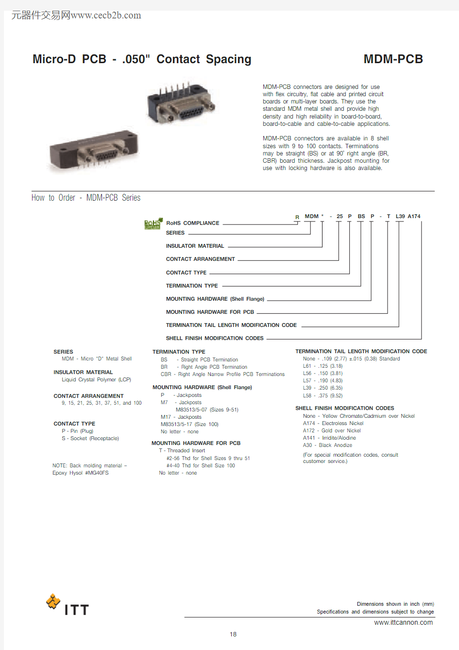
MDM-PCB connectors are designed for use with flex circuitry, flat cable and printed circuit boards or multi-layer boards. They use the standard MDM metal shell and provide high density and high reliability in board-to-board,board-to-cable and cable-to-cable applications.MDM-PCB connectors are available in 8 shell sizes with 9 to 100 contacts. Terminations may be straight (BS) or at 90? right angle (BR,CBR) board thickness. Jackpost mounting for use with locking hardware is also available.
SERIES
INSULATOR MATERIAL
CONTACT ARRANGEMENT
CONTACT TYPE TERMINATION TYPE
MOUNTING HARDWARE (Shell Flange) MOUNTING HARDWARE FOR PCB
TERMINATION TAIL LENGTH MODIFICATION CODE SHELL FINISH MODIFICATION CODES
SERIES
MOUNTING HARDWARE FOR PCB TERMINATION TAIL LENGTH MODIFICATION CODE SHELL FINISH MODIFICATION CODES
INSULATOR MATERIAL
CONTACT ARRANGEMENT
CONTACT TYPE
TERMINATION TYPE
MOUNTING HARDWARE (Shell Flange)
MDM - Micro "D" Metal Shell T -Threaded Insert
#2-56 Thd for Shell Sizes 9 thru 51 #4-40 Thd for Shell Size 100No letter - none
None - .109 (2.77) ±.015 (0.38) Standard L61 - .125 (3.18)L56 - .150 (3.81)L57 - .190 (4.83)L39 - .250 (6.35)L58 - .375 (9.52)None - Yellow Chromate/Cadmium over Nickel A174 - Electroless Nickel A172 - Gold over Nickel A141 - Irridite/Alodine A30 - Black Anodize (For special modification codes, consult customer service.)NOTE: Back molding material – Epoxy Hysol #MG40FS
MDM * - - 25P
P BS
T
L39 A174
Liquid Crystal Polymer (LCP)9, 15, 21, 25, 31, 37, 51, and 100
P -Pin (Plug)
S -Socket (Receptacle)
BS - Straight PCB Termination BR - Right Angle PCB Termination
CBR - Right Angle Narrow Profile PCB Terminations P -Jackposts M7 - Jackposts M83513/5-07 (Sizes 9-51)M17 - Jackposts
M83513/5-17 (Size 100)No letter - none RoHS COMPLIANCE R
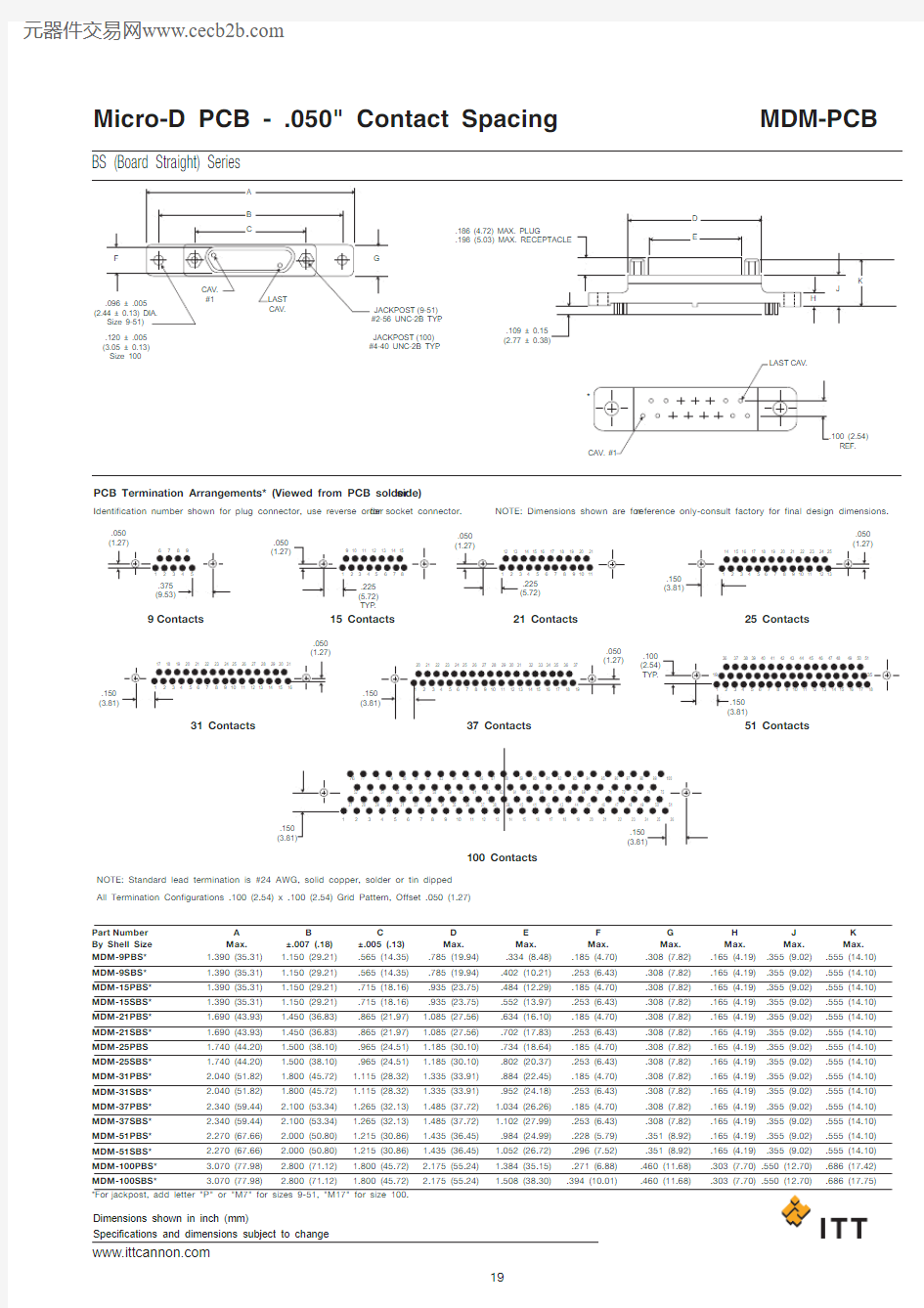
BS (Board Straight) Series
.120 ± .005(3.05 ± 0.13)Size 100
(9-51).JACKPOST (100)#4-40 UNC-2B TYP .
.186 (4.72) MAX. PLUG
.109 ± 0.15(2.77 ± 0.38)
.050(1.27)
.050.050.100TYP .
.150.050(1.27)
.050.050.150TYP .
PCB Termination Arrangements* (Viewed from PCB solder side)
9Contacts 31 Contacts 15 Contacts
100 Contacts
51 Contacts
21 Contacts
25 Contacts
Identification number shown for plug connector, use reverse order for socket connector.
NOTE: Standard lead termination is #24 AWG, solid copper, solder or tin dipped All Termination Configurations .100 (2.54) x .100 (2.54) Grid Pattern, Offset .050 (1.27)
NOTE: Dimensions shown are for reference only-consult factory for final design dimensions.
REF.
B
±.007 (.18)Part Number By Shell Size A Max.C
±.005 (.13)D Max.E Max.F Max.G Max.H Max.J Max.K Max.MDM-9PBS*MDM-9SBS*MDM-15PBS*MDM-15SBS*MDM-21PBS*MDM-21SBS*MDM-25PBS MDM-25SBS*MDM-31PBS*MDM-31SBS*MDM-37PBS*MDM-37SBS*MDM-51PBS*MDM-51SBS*MDM-100PBS*
1.390 (35.31)1.390 (35.31)1.390 (35.31)1.390 (35.31)1.690 (43.93)1.690 (43.93)1.740 (44.20)1.740 (44.20)
2.040 (51.82)2.040 (51.82)2.340 (59.44)2.340 (59.44)2.270 (67.66)2.270 (67.66)
3.070 (77.98)
1.150 (29.21)1.150 (29.21)1.150 (29.21)1.150 (29.21)1.450 (36.83)1.450 (36.83)1.500 (38.10)1.500 (38.10)1.800 (45.72)1.800 (45.72)
2.100 (5
3.34)2.100 (53.34)2.000 (50.80)2.000 (50.80)2.800 (71.12)
.565 (14.35).565 (14.35).715 (18.16).715 (18.16).865 (21.97).865 (21.97).965 (24.51).965 (24.51)1.115 (28.32)1.115 (28.32)1.265 (32.13)1.265 (32.13)1.215 (30.86)1.215 (30.86)1.800 (45.72)
.785 (19.94).785 (19.94).935 (23.75).935 (23.75)1.085 (27.56)1.085 (27.56)1.185 (30.10)1.185 (30.10)1.335 (33.91)1.335 (33.91)1.485 (37.72)1.485 (37.72)1.435 (36.45)1.435 (36.45)2.175 (55.24).334 (8.48).402 (10.21).484 (12.29).552 (13.97).634 (16.10).702 (17.83).734 (18.64).802 (20.37).884 (22.45).952 (24.18)1.034 (26.26)1.102 (27.99).984 (24.99)1.052 (26.72)1.384 (35.15).185 (4.70).253 (6.43).185 (4.70).253 (6.43).185 (4.70).253 (6.43).185 (4.70).253 (6.43).185 (4.70).253 (6.43).185 (4.70).253 (6.43).228 (5.79).296 (7.52).271 (6.88).308 (7.82).308 (7.82).308 (7.82).308 (7.82).308 (7.82).308 (7.82).308 (7.82).308 (7.82).308 (7.82).308 (7.82).308 (7.82).308 (7.82).351 (8.92).351 (8.92).460 (11.68).165 (4.19).165 (4.19).165 (4.19).165 (4.19).165 (4.19).165 (4.19).165 (4.19).165 (4.19).165 (4.19).165 (4.19).165 (4.19).165 (4.19).165 (4.19).165 (4.19)
.303 (7.70).355 (9.02).355 (9.02).355 (9.02).355 (9.02).355 (9.02).355 (9.02).355 (9.02).355 (9.02).355 (9.02).355 (9.02).355 (9.02).355 (9.02).355 (9.02).355 (9.02)
.550 (12.70).555 (14.10).555 (14.10).555 (14.10).555 (14.10).555 (14.10).555 (14.10).555 (14.10).555 (14.10).555 (14.10).555 (14.10).555 (14.10).555 (14.10).555 (14.10).555 (14.10).686 (17.42)
BR (Board Right Angle) Series
.300
PCB Termination Arrangements (Viewed from bottom of connector, PCB solder side.)Identification number shown for plug connector, use reverse order for socket connector.
.100TYP .
.150.150(3.81)
.150(4.45)
.150.150.150(5.72)
9Contacts
31 Contacts 15Contacts 37 Contacts 51 Contacts
21 Contacts
25 Contacts
27 28 29 30 31 32 33 3435 36 37 38 39 40 41 42 43 44 45 46 47 48 49 50 511
2
3
4
5
6
7
8
910
11 12 13 14 15 16 17 18 19 20 21 22 23 24 25 26
100 Contacts
NOTE: Standard lead termination is #24 AWG, gold plated, solid copper, solder or tin dripped.*For jackpost, add letter "P" or "M7" for sizes 9-51, "M17" for size 100.
Part Number By Shell Size MDM-9PBR*MDM-9SBR*MDM-15PBR*MDM-15SBR*MDM-21PBR*MDM-21SBR*MDM-25PBR*MDM-25SBR*MDM-31PBR*MDM-31SBR*MDM-37PBR*MDM-37SBR*MDM-51PBR*MDM-51SBR*MDM-100PBR*MDM-100SBR*
1.390 (35.31)1.390 (35.31)1.540 (39.12)1.540 (39.12)1.690 (4
2.93)1.690 (42.93)1.790 (45.47)1.790 (45.47)2.040 (51.82)2.040 (51.52)2.340 (59.44)2.340 (59.44)1.875 (47.63)1.875 (47.63) 2.74 (69.72) 2.74 (69.72)
1.150 (29.21)1.150 (29.21)1.300 (33.02)1.300 (33.02)1.450 (36.83)1.450 (36.83)1.550 (39.37)1.550 (39.37)1.800 (45.72)1.800 (45.72)
2.100 (5
3.34)2.100 (53.34)1.600 (40.64)1.600 (40.64)2.500 (63.50)2.500 (63.50)
.565 (14.35).565 (14.35).715 (18.16).715 (18.16).865 (21.97).865 (21.97).965 (24.51).965 (24.51)1.115 (28.32)1.115 (28.32)1.265 (32.13)1.265 (32.13)1.215 (30.86)1.215 (30.86)1.800 (45.72)1.800 (45.72)
.334 (8.48).402 (10.21).484 (12.29).552 (13.97).634 (16.10).702 (17.83).734 (18.64).802 (20.37).884 (22.45).952 (24.18)1.034 (26.26)1.102 (27.99).984 (24.99)1.052 (26.72)1.384 (35.15)1.508 (38.10)
.185 (4.70).253 (6.43).185 (4.70).253 (6.43).185 (4.70).253 (6.43).185 (4.70).253 (6.43).185 (4.70).253 (6.43).185 (4.70).253 (6.43).228 (5.79).296 (7.52).271 (6.88).394 (10.01)
.455 (11.56).455 (11.56).455 (11.56).455 (11.56).455 (11.56).455 (11.56).455 (11.56).455 (11.56).455 (11.56).455 (11.56).455 (11.56).455 (11.56).565 (14.35).565 (14.35).755 (19.18).755 (19.18)
.308 (7.82).308 (7.82).308 (7.82).308 (7.82).308 (7.82).308 (7.82).308 (7.82).308 (7.82).308 (7.82).308 (7.82).308 (7.82).308 (7.82).351 (8.92).351 (8.92).394 (10.01).394 (10.01)
A Max.B
±.007 (.18)C
±.005 (.13)D Max.E Max.F Max.G Max.All Termination Configurations .100 (2.54) x .100 (2.54) Grid Pattern, Offset .050 (1.27).
CBR (Condensed Board Right Angle) Series
PCB Termination Arrangements (Viewed from bottom of connector, PCB solder side.)Identification number shown for plug connector, use reverse order for socket connector.
1
3572410
12141617192123252729373941434547
495128
30
32
3436384042
444648
505355575961
6365
6769717375
52545658606264666870
7274
76788082
848688
9092949698100
77
79
81
83
85
87
8991
93
9597
99
18202226
31
33352
468
9111315JACKPOST 2-56..186 (4.72)MAX.PLUG .198 (5.03)DIA.TYP .(Size 9-51)
FOR 31: 1.085(27.56) MAX.FOR 37: 1.185(30.10) MAX.FOR 51: 1.225(31.12) MAX.
**JACKPOST .
100 VIEW
.108.020.020(2.54 ± 0.13)
9Contacts View X
15Contacts View X
21Contacts View X
25 Contacts View X
100 Contacts View W
51 Contacts View Y 37 Contacts View Y 31 Contacts View Y NOTE: Standard lead termination is #24 AWG, solid copper, solder or tin dripped. *For jackpost, add letter "P" or "M7" for sizes 9-51, "M17" for size 100.
By Shell Size MDM-9PCBR*MDM-9SCBR*MDM-15PCBR*MDM-15SCBR*MDM-21PCBR*MDM-21SCBR*MDM-25PCBR*MDM-25SCBR*MDM-31PCBR*MDM-31SCBR*MDM-37PCBR*MDM-37SCBR*MDM-51PCBR*MDM-51SCBR*MDM-100PCBR*MDM-100SCBR*
.785 (19.94) .785 (19.94) .935 (23.75) .935 (23.75) 1.085 (27.56) 1.085 (27.56) 1.185 (30.10) 1.185 (30.10) 1.335 (33.91) 1.335 (33.91) 1.485 (37.72) 1.485 (37.72) 1.435 (36.45) 1.435 (36.45) 2.170 (55.12) 2.170 (55.12)
.565 (14.35) .565 (14.35) .715 (18.16) .715 (18.16) .865 (21.97) .865 (21.97) .965 (24.51) .965 (24.51) 1.115 (28.32) 1.115 (28.32) 1.265 (32.13) 1.265 (32.13) 1.215 (30.86) 1.215 (30.86) 1.800 (45.72) 1.800 (45.72)
.334 (8.48) .402 (10.21) .484 (12.29) .552 (13.97) .634 (16.10) .702 (17.83) .734 (18.64) .802 (20.37) .884 (22.45) .952 (24.18) 1.034 (26.26) 1.102 (27.99) .984 (24.99) 1.052 (26.72) 1.384 (35.15) 1.508 (38.10)
.308 (7.82) .308 (7.82) .308 (7.82) .308 (7.82) .308 (7.82) .308 (7.82) .308 (7.82) .308 (7.82) .308 (7.82) .308 (7.82) .308 (7.82) .308 (7.82) .351 (8.92) .351 (8.92) .394 (10.01) .394 (10.01)
.185 (4.70) .253 (6.43) .185 (4.70) .253 (6.43) .185 (4.70) .253 (6.43) .184 (4.70) .253 (6.43) .185 (4.70) .253 (6.43) .185 (4.70) .253 (6.43) .228 (5.79) .296 (7.52) .271 (6.88) .394 (10.01)
.420 (10.67) .420 (10.67) .420 (10.67) .420 (10.67) .420 (10.67) .420 (10.67) .420 (10.67) .420 (10.67) .520 (13.21) .520 (13.21) .520 (13.21) .520 (13.21) .650 (16.15) .650 (16.15) 1.000 (25.40) 1.000 (25.40)
.250 (6.35) .250 (6.35) .250 (6.35) .250 (6.35) .250 (6.35) .250 (6.35) .250 (6.35) .250 (6.35) .250 (6.35) .250 (6.35) .250 (6.35) .250 (6.35) .300 (7.62) .300 (7.62) .400 (10.16) .400 (10.16)
.230 (5.81) .230 (5.81) .130 (3.30) .130 (3.30) .130 (3.30) .130 (3.30) .130 (3.30) .130 (3.30) .130 (3.30) .130 (3.30) .130 (3.30) .130 (3.30) .150 (3.81) .150 (3.81) .200 (5.08) .200 (5.08)
Max.±.005 (.13)±.010 (.25)±.010 (.25)Max.Max.Max.Max.All Termination Configurations .100 (2.54) x .100 (2.54) Grid Pattern, Offset .050 (1.27).