SFH 5410
IR-Empf?nger für Fernbedienungen
IR-Receiver for Remote Control Systems
Lead (Pb) Free Product - RoHS Compliant
2008-10-061
Beschreibung
Der SFH 5410 ist ein Infrarot-Empf?nger für die Erkennung von Signalen aus Infrarot-Fernbedie-nungssystemen und bestehen aus Fotodiode, Vorverst?rker, automatischer Verst?rkungsrege-lung, Bandpa?-Filter und Demodulator. Das Ge-h?use ist zur Unterdrückung des Tageslichtein-flusses schwarz eingef?rbt.Wesentliche Merkmale
?IC mit monolithisch integrierter Fotodiode (Ein-Chip L?sung)
?Speziell geeignet für Anwendungen bei 940 nm ?Hohe Empfindlichkeit
?Verschiedene Tr?gerfrequenzen erh?ltlich ?TTL und CMOS kompatibel ?Ausgang: aktiv …Low“Anwendungen
?Empf?nger in Fernbedienungen für TV,
Videorecorder, HiFi, Satellitenempf?nger und CD-Spieler
?Um hohe Sicherheit bei der Datenübertragung zu erreichen, sind fehlerkorrigierende Codes einzusetzen
Description
The SFH 5410 is a IR receivers to detect light from infrared remote control systems. The IC includes photodiode, preamplifier, automatic gain control, bandpass and demodulator. The black-colored package is designed as daylight-cutoff filter.
Features
?IC with monolithic integrated photodiode (single chip solution)
?Especially suitable for applications of 940 nm ?High sensitivity
?Various carrier frequencies available ?TTL and CMOS compatibility ?Output: active Low Applications
?Remote control module for TV sets, VCRs, hi-fi audio receivers, SAT receivers and compact disk players
?For safe data transmission error tolerant codes have to be used
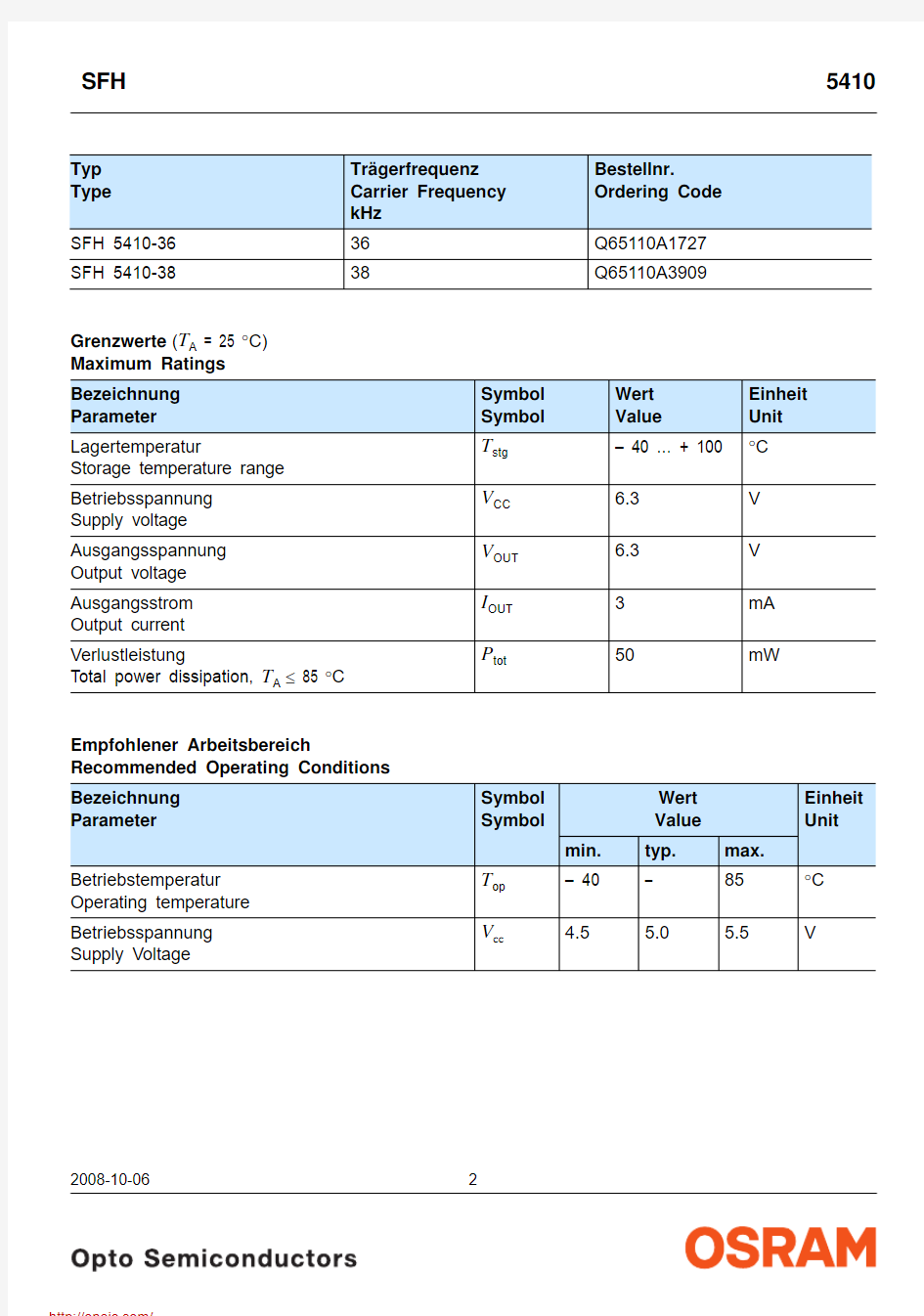
Typ Type Tr?gerfrequenz
Carrier Frequency
kHz
Bestellnr.
Ordering Code
SFH 5410-3636Q65110A1727 SFH 5410-3838Q65110A3909
Grenzwerte (T A = 25 °C)
Maximum Ratings
Bezeichnung Parameter Symbol
Symbol
Wert
Value
Einheit
Unit
Lagertemperatur
Storage temperature range T
stg
– 40 … + 100°C
Betriebsspannung Supply voltage V
CC
6.3V
Ausgangsspannung Output voltage V
OUT
6.3V
Ausgangsstrom Output current I
OUT
3mA
Verlustleistung
Total power dissipation, T A≤ 85 °C P
tot
50mW
Empfohlener Arbeitsbereich Recommended Operating Conditions
Bezeichnung Parameter Symbol
Symbol
Wert
Value
Einheit
Unit
min.typ.max.
Betriebstemperatur Operating temperature T
op
– 40– 85°C
Betriebsspannung Supply Voltage V
cc
4.5
5.0 5.5V
2008-10-062
2008-10-063
Kennwerte (T A = 25 °C) Characteristics Bezeichnung Parameter
Symbol Symbol
Wert Value Einheit Unit min.
typ.max.Stromaufnahme, V CC = 5 V, E = 0 Current consumption
I CC
– 1.3–mA Wellenl?nge der max. Fotoempfindlichkeit Wavelength of max. sensitivity
λs max –940–nm Spektraler Bereich der Fotoempfindlichkeit 1) Spectral range of sensitivity 1)
Au?erhalb des spezifizierten Bereiches der Fotoempfindlichkeit besitzt der SFH 5410 eine Restempfindlichkeit. D.h. Lichtquellen au?erhalb des spezifizierten Wellenl?ngenbereiches des Sensors k?nnen den Baustein beeinflussen und zum Durchschalten führen.
1)
Beyond the specified spectral range of sensitivity the SFH 5410 has a strongly reduced, but non-zero sensitivity. Light sources with wavelengths outside the spectral range may influence the device and result in switching.
λ10%
830
–
1100
nm Ausgangsspannung Output voltage
Output “High” - (I out = 10 μA) Output “Low” - (I out = 500 μA) V OUT high V OUT low
V CC -0.5–––
– 0.5V
Tr?gerfrequenz Carrier frequency SFH 5410-36 SFH 5410-38
f 0
–
36 38
–
kHz
Min. Bestrahlungsst?rke (Testsignal, s. Fig. 3) Min. Threshold irradiance (test signal, see Fig. 3) f = f 0, t p,I = 600 μs
E e min
– 1.4–
mW/m 2
Min. Eingangspulsbreite …ON“ (Testsignal, s. Fig. 3)2)
Min. Input pulse width “ON” (test signal, see Fig. 3)2)
t p,I 6/f O
––μs
Ausgangspulsbreite …ON“ (Testsignal, s. Fig. 3)
Output pulse width “ON” (test signal, see Fig. 3, E e = 4 mW/m 2)
t p,O t p,I
– 6/f O
–
t p,I
+ 6/f O
μs
50%-Filterbandbreite, f = f O , E V = 0, V CC = 5 V 50%-Filter bandwidth
Δf 50%
3–6kHz
2)Die volle Empfindlichkeit wird bei einer Burstl?nge von mindestens 6 Pulsen erreicht. Die Reichweite bei
Verwendung eines typischen Senders (SFH 4510/SFH 4515, I F = 500 mA) betr?gt etwa 15 m.
2) A minimum burst length of 6 pulses is necessary for full sensitivity. The transmission distance with a typical
transmitter (SFH 4510/SFH 4515, I F = 500 mA) is about 15 m.
Figure 1Blockschaltbild / Block Diagram
Figure 2Externe Beschaltung / External Circuit
2008-10-064
2008-10-065
Figure 3Optisches Testsignal / Optical Test Signal
Anschlu?belegung Pin configuration Pin Pin Beschreibung Description 1OUT 2GND 3
V CC
Anmerkungen / Notes
- Abh?ngig von den Umgebungsbedingungen, z.B in Form von externen Lichtquellen, elektro-magnetischer Strahlung und Rauschen der Versorgungsspannung, kann es zum sporadischen Durchschalten des Ausgang kommen, selbst wenn kein optisches Signal angelegt wird! Um Fehlinterpretationen der übermittelten Daten zu verhindern, sind fehlerkorrigierende Codes einzusetzen.
- Environmental conditions, e.g. external light sources, electromagnetic interference and supply voltage noise , may cause sporadic switching at the output, even without an optical input signal! To avoid misinterpretation of the transmitted data, error tolerant codes must be used.
Für weitere Informationen lesen Sie bitte die Application Note des SFH 5110:For further information please read the application note of the SFH 5110:Gerneral Application Note for SFH 511X
2008-10-066
Relative Spectral Sensitivity
Directional Characteristics
Relative Sensitivity
Ma?zeichnung
Package Outlines
Ma?e in mm (inch) / Dimensions in mm (inch). Empfohlenes L?tpaddesign
Recommended Solderpad Design
Ma?e in mm / Dimensions in mm.
2008-10-067
2008-10-06
8
L?tbedingungen
Vorbehandlung nach JEDEC Level 4 Soldering Conditions
Preconditioning acc. to JEDEC Level 4 Reflow L?tprofil für bleifreies L?ten
(nach J-STD-020C) Reflow Soldering Profile for lead free soldering
(acc. to J-STD-020C)
Published by
OSRAM Opto Semiconductors GmbH
Wernerwerkstrasse 2, D-93049 Regensburg https://www.doczj.com/doc/8e16670547.html, ? All Rights Reserved.
The information describes the type of component and shall not be considered as assured characteristics.
Terms of delivery and rights to change design reserved. Due to technical requirements components may contain dangerous substances. For information on the types in question please contact our Sales Organization.Packing
Please use the recycling operators known to you. We can also help you – get in touch with your nearest sales office. By agreement we will take packing material back, if it is sorted. You must bear the costs of transport. For packing material that is returned to us unsorted or which we are not obliged to accept, we shall have to invoice you for any costs incurred.
Components used in life-support devices or systems must be expressly authorized for such purpose! Critical components 1 , may only be used in life-support devices or systems 2 with the express written approval of OSRAM OS.1
A critical component is a component usedin a life-support device or system whose failure can reasonably be expected to cause the failure of that life-support device or system, or to affect its safety or effectiveness of that device or system.2
Life support devices or systems are intended (a) to be implanted in the human body, or (b) to support and/or maintain and sustain human life. If they fail, it is reasonable to assume that the health of the user may be endangered.
分销商库存信息:
OSRAM
SFH 5410-38-Z SFH 5410-36-Z