DATA SHEET
Preliminary speci?cation
File under Integrated Circuits, IC021996Oct24
INTEGRATED CIRCUITS
SAA4997H
VErtical Reconstruction IC (VERIC) for PALplus
VErtical Reconstruction IC (VERIC) for PALplus
SAA4997H
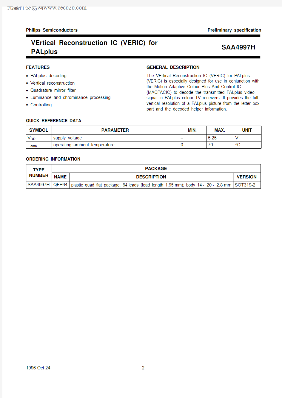
FEATURES ?PALplus decoding ?Vertical reconstruction ?Quadrature mirror filter
?Luminance and chrominance processing ?Controlling.
GENERAL DESCRIPTION
The VErtical Reconstruction IC (VERIC) for PALplus
(VERIC) is especially designed for use in conjunction with the Motion Adaptive Colour Plus And Control IC
(MACPACIC) to decode the transmitted PALplus video signal in PALplus colour TV receivers. It provides the full vertical resolution of a PALplus picture from the letter box part and the decoded helper information.
QUICK REFERENCE DATA ORDERING INFORMATION SYMBOL PARAMETER
MIN.
MAX.UNIT
V DD supply voltage
? 5.25
V T amb
operating ambient temperature
70
°C
TYPE NUMBER
PACKAGE
NAME
DESCRIPTION
VERSION
SAA4997H QFP64plastic quad ?at package; 64leads (lead length 1.95mm); body 14×20×2.8mm SOT319-2
SAA4997H PALplus
BLOCK DIAGRAMS
SAA4997H PALplus
SAA4997H PALplus
PINNING
SYMBOL PIN TYPE DESCRIPTION
Y_VE_11output luminance output data bit1
Y_VE_02output luminance output data bit0
U_VE_13output chrominance output data bit1 U-component
U_VE_04output chrominance output data bit0 U-component
V_VE_15output chrominance output data bit1 V-component
V_VE_06output chrominance output data bit0 V-component
V SS17input ground1
V DD18input positive supply voltage1 (+5V)
n.c.9?not connected
n.c.10?not connected
n.c.11?not connected
n.c.12?not connected
n.c.13?not connected
n.c.14?not connected
n.c.15?not connected
n.c.16?not connected
HREF_MA17input horizontal reference
n.c.18?not connected
VA_AI19input vertical reference pulse related to output data
INTPOL20input INTPOL=1: PALplus interpolation active
INTPOL=0: VERIC switched to bypass mode (standard signal)
FILM21input FILM=0: CAMERA mode
FILM=1: FILM mode
EVEN_FIELD22input EVEN_FIELD=0: odd ?eld related to MACPACIC input data
EVEN_FIELD=1: even ?eld related to MACPACIC input data
CLK_16B223input buffered clock input (16MHz)
V SS224input ground2
V DD225input positive supply voltage2 (+5V)
TCK26input boundary scan test clock input
TMS27input boundary scan test mode select input
TDI28input boundary scan test data input
TDO_VE29output boundary scan test data output
TRSTN30input boundary scan test reset input
n.c.31?not connected
n.c.32?not connected
TEST133tbf test pins
TEST234tbf
TEST335tbf
CLK_32B336input buffered clock input (32MHz)
V SS337input ground3
SAA4997H PALplus
SYMBOL PIN TYPE DESCRIPTION
V DD338input positive supply voltage3 (+5V)
OE_FM339output output enable ?eld memory3
RE_FM340output read enable ?eld memory3
V_FM23_141input chrominance input data bit1 V-component
V_FM23_042input chrominance input data bit0 V-component
U_FM23_143input chrominance input data bit1 U-component
U_FM23_044input chrominance input data bit0 U-component
Y_FM23_745input Y input data bit7
Y_FM23_646input Y input data bit6
Y_FM23_547input Y input data bit5
Y_FM23_448input Y input data bit4
Y_FM23_349input Y input data bit3
n.c.50?not connected
Y_FM23_251input Y input data bit2
Y_FM23_152input Y input data bit1
Y_FM23_053input Y input data bit0
RSTR_FM2354output reset read ?eld memory2 and 3
RE_FM255output read enable ?eld memory2
OE_FM256output output enable ?eld memory2
V DD457input positive supply voltage4 (+5V)
V SS458input ground4
Y_VE_759output luminance output data bit7
Y_VE_660output luminance output data bit6
Y_VE_561output luminance output data bit5
Y_VE_462output luminance output data bit4
Y_VE_363output luminance output data bit3
Y_VE_264output luminance output data bit2
PALplus
SAA4997H
Fig.3 Pin configuration.
handbook, full pagewidth
SAA4997H
MGE442
12345678910111213141516171819
Y_VE_1Y_VE_0U_VE_1U_VE_0V_VE_1V_VE_0V SS1V DD1n.c.n.c.n.c.n.c.n.c.n.c.n.c.n.c
HREF_MA
n.c.VA_AI
Y_FM23_2n.c.Y_FM23_3Y_FM23_4Y_FM23_5Y_FM23_6Y_FM23_7U_FM23_0U_FM23_1V_FM23_0V_FM23_1RE_FM3OE_FM3V DD3V SS3CLK_32B3TEST3TEST2TEST1
515049484746454443
42414039383736353433
20
21
22
23
24
25
26
27
28
29
30
31
32
64636261605958575655545352Y _V E _2
Y _V E _3
Y _V E _4
Y _V E _5
Y _V E _6
Y _V E _7
V S S 4
V D D 4
O E _F M 2
R E _F M 2
R S T R _F M 23
Y _F M 23_0
Y _F M 23_1
I N T P O L F I L M E V E N _F I E L D C L K _16B 2V S S 2V D D 2T C K T M S T D I T D O _V E T R S T N n .c .n .c .
PALplus
SAA4997H
FUNCTIONAL DESCRIPTION
Introduction
As shown in Fig.2 the PALplus module consists of two special integrated circuits:
?Motion Adaptive Colour Plus And Control IC (MACPACIC)
?VErtical Reconstruction IC (VERIC)
and four field memories TMS4C2970.
The MACPACIC and the VERIC are intended to generate digitally decoded 50Hz YUV signals. The MACPACIC performs the decompanding function for the helper lines and the motion adaptive luminance/chrominance separation. Furthermore, PALplus system controlling, memory controlling and clock generation are carried out in this circuit.
The function of the VERIC is to reconstruct the separated 2×72helper lines and the 430main lines into a standard 576lines frame according the PALplus system description “REV2.0”. Chrominance is converted from 430lines to 576lines using a vertical sample rate converter.
The data of the VERIC are clocked out with 16MHz. The Y:U:V bandwidth ratio is 4:1:1.
The functional block diagram of the VERIC is shown in Fig.1. The device consists of 3main parts:?Luminance processing
?Chrominance processing
?Controlling.
The input data are delivered by the field memories FM2 and FM3, which include multiplexed first and second field data processed by the MACPACIC. The luminance and chrominance input data of the VERIC are clocked with 32MHz (CLK_32B3). Internally the device operates at 32or16MHz clock frequency.
Luminance processing
In the PALplus encoder the luminance signal is separated vertically into two sub-bands by a special Quadrature Mirror Filter (QMF).
A vertical low-pass sub-band consists of the 430main letter box lines per frame, and a vertical high-pass
sub-band includes the 144helper lines per frame.
The used QMF technique has two advantages:?Essentially loss-free data processing ?Cancellation of alias components in the main and helper signal in the decoder.The luminance vertical conversion process in the decoder is complementary to that of the encoder.
In the decoder the inverse QMF function is implemented to recombine the two separated sub-bands and to generate the original video signal with 576active lines per frame.
Each output line is calculated from up to seven input lines stored in line memories containing main or helper information. The various lines are multiplied by switched coefficients, changing every line within a sequence of four lines, depending on the specific mode (CAMERA or FILM).
In case of standard PAL reception, the VERIC is switched to bypass mode controlled by the signal INTPOL.
For multi-PIP processing the VERIC is also switched to bypass mode, but controlling of FM2/3 is different (see Fig.6). The total signal delay between the MACPACIC input and the VERIC output is one line for this mode.
FM2/3 are driven with 32MHz clock frequency.
The non-multiplexed input data are clocked out with
16MHz.
Chrominance processing
The chrominance processing is carried out by the vertical interpolation filter (poly phase filter).
In CAMERA and FILM mode, intra-field vertical sample rate conversion is carried out.
One output line is calculated out of three or four lines in CAMERA or FILM mode using different coefficients or passed through in bypass mode.
Control functions
The VERIC controller generates the necessary internal control signals for the line memories, formatters, reformatters, the selector signals for the multiplexers and the read signals for the field memories FM2/3.
The system control input signals EVEN_FIELD, INTPOL and FILM are derived from the control part of the MACPACIC. The field selection information EVEN_FIELD is related to the input data of the MACPACIC and is adapted in the VERIC to its input data.
The control functions are described in Tables1 and 2. Table 1EVEN_FIELD
VALUE STATUS
EVEN_FIELD=1even ?eld selected
EVEN_FIELD=0odd ?eld selected
PALplus
SAA4997H
Table 2
INTPOL and FILM Modes and delays
The PALplus module can operate in two different hardware configurations:
?Full PALplus configuration (MACPACIC and VERIC)?Stand alone MACPACIC.
The vertical interpolation of the VERIC can be activated by the signal INTPOL depending on the PALplus signalling bits, transmitted in line 23 indicating the type of signal being received.
However, the delay between input data of the MACPACIC and output data of the VERIC always has to be 1.5fields.This is achieved with a suitable read timing of the field memories FM2 and FM3 controlled by VA_AI which is derived from the field length measurement in the MACPACIC.
In case of INTPOL =LOW and additionally FILM =HIGH (FILM mode), the VERIC is switched to multi-PIP mode.In case the delay between input of the MACPACIC and output of the VERIC is one line (1024CLK_16 periods).The line and pixel timings of the VERIC are shown in Figures 5to 14.
VALUE
STATUS
INTPOL =0FILM =0bypass mode;standard signals INTPOL =1FILM =0interpolation active;
PALplus CAMERA mode INTPOL =0FILM =1bypass mode; multi-PIP INTPOL =1FILM =1
interpolation active;PALplus FILM mode
Table 3
Delays
Input/Output formats I NPUT FORMATS
The luminance input range of the main and helper signal has the following values:
Main signal: black =16, white =191 (straight binary)Helper signal:±70, mid =128 (straight binary)
Chrominance format:±90, mid =0 (two’s complement).O UTPUT FORMATS
Luminance format: black =16, white =191 (straight binary)
Blanking: code 16
Chrominance format:±90, mid =0 (two’s complement)Blanking: code 0.Test activities
The pins TEST1, TEST2 and TEST3 are provided to perform the IC test activities, such as scan test.The pins TRSTN, TDI, TMS, TCK and TDO_VE are intended for a boundary scan test.
MODE FIELD VERIC I/O DELAY FILM mode
?rst 2lines second
3lines CAMERA mode
?rst 3lines second
4lines
PALplus
SAA4997H
DC CHARACTERISTICS T j =0to 125°C SYMBOL PARAMETER
CONDITIONS
MIN.
TYP .
MAX.UNIT
Supply V DD supply voltage 4.75 5.0 5.25V I DD supply current
V DD =5V
?
?80mA I DD(q)quiescent supply current
all inputs to V DD or V SS ?
?
100μA Inputs V IL LOW level input voltage ?0.5?+0.8V V IH HIGH level input voltage 2.0?V DD V I LI input leakage current
?
?
1.0μA Outputs V OL LOW level output voltage I O =20μA ??0.1V V OH HIGH level output voltage I O =20μA V DD ?0.1?
?V I OL LOW level output current V O =0.5V 4.0??mA I OH
HIGH level output current
V O =V DD ?0.5V
4.0
?
?
mA
AC CHARACTERISTICS T j =0to 125°C SYMBOL
PARAMETER
CONDITIONS
MIN.
TYP .
MAX.
UNIT
Clock timing CLK_32B3(see Fig.4)T CY(32)cycle time 28.131.25?ns t H HIGH time 9.2??ns t L LOW time 9.2??ns t r rise time 2.0? 4.0ns t f fall time
2.0? 4.0ns ?f clk deviation of clock frequency ?10?+10%Clock timing CLK_16B2(see Fig.4)
T CY(16)cycle time 56.2??ns t H HIGH time 20.5??ns t L LOW time 20.5??ns t r rise time 2.0? 4.0ns t f fall time 4.0? 4.0ns δ
duty cycle
40
?
50
%
δt H t L
----=
SAA4997H PALplus
SYMBOL PARAMETER CONDITIONS MIN.TYP.MAX.UNIT Input data timing (CLK_32)
t su input data set-up time
CLK_16B2?4.7??ns
Y and UV_FM23?0.8??ns
t h(i)input data hold time
CLK_16B2 5.1??ns
Y and UV_FM23 5.2??ns Input control timing (CLK_16B2)
HREF_MA,VA_AI,FILM,EVEN_FIELD AND INTPOL
t su input data set-up time 4.5??ns
t h(i)input data hold time0.1??ns Output data timing (CLK_16B2)
Y AND UV_FM23
t h(o)output data hold time C L=15pF8??ns
t d(o)output data delay time C L=15pF??27ns Output control timing (CLK_32B3)
OE_FM2,OE_FM3,RE_FM2,RE_FM3AND RSTR_FM23
t h(o)output data hold time C L=15pF5??ns
t d(o)output data delay time C L=15pF??20ns Delays
t w(HREF)HREF_MA pulse width?60×T CY(16)?ns
?127×T CY(32)?ns
t d(RE)delay
RE_FM2/3to HREF_MA
t w(RE)RE_FM2/3 pulse width?1680×T CY(32)?ns
t d(VE)(MA)delay HREF_MA to YUV_VE?80×T CY(16)?ns
t d(VE)delay data input to output?16×T CY(16)?ns
t d(VE)delay data input to output multi-PIP?2×T CY(16)?ns
t d(RSTR)delay RSTR multi-PIP?2016×T CY(32)?ns
t d(FM2)delay FM2 input to output multi-PIP?2040×T CY(32)?ns
PALplus
SAA4997H
TIMING
Fig.4 Data/control input/output set-up and hold timing.
Data input: CLK =CLK_32B3Data output: CLK =CLK_16B2Control input: CLK =CLK_16B2Control output: CLK =CLK_32B3
handbook, full pagewidth
MGE445
t r
t f
t H
t L
90%50%10%
t h(o)
t d(o)
t su
t h(i)
CLK
DATA/CONTROL XX Dn
D(n +1)
SAA4997H PALplus
SAA4997H PALplus
SAA4997H PALplus
SAA4997H PALplus
SAA4997H PALplus
SAA4997H PALplus
SAA4997H PALplus
SAA4997H PALplus