The Inerter Concept and Its Application
Malcolm C.Smith
Department of Engineering
University of Cambridge
U.K.
Society of Instrument and Control Engineers(SICE)
Annual Conference
Fukui,Japan
4August2003
Plenary Lecture
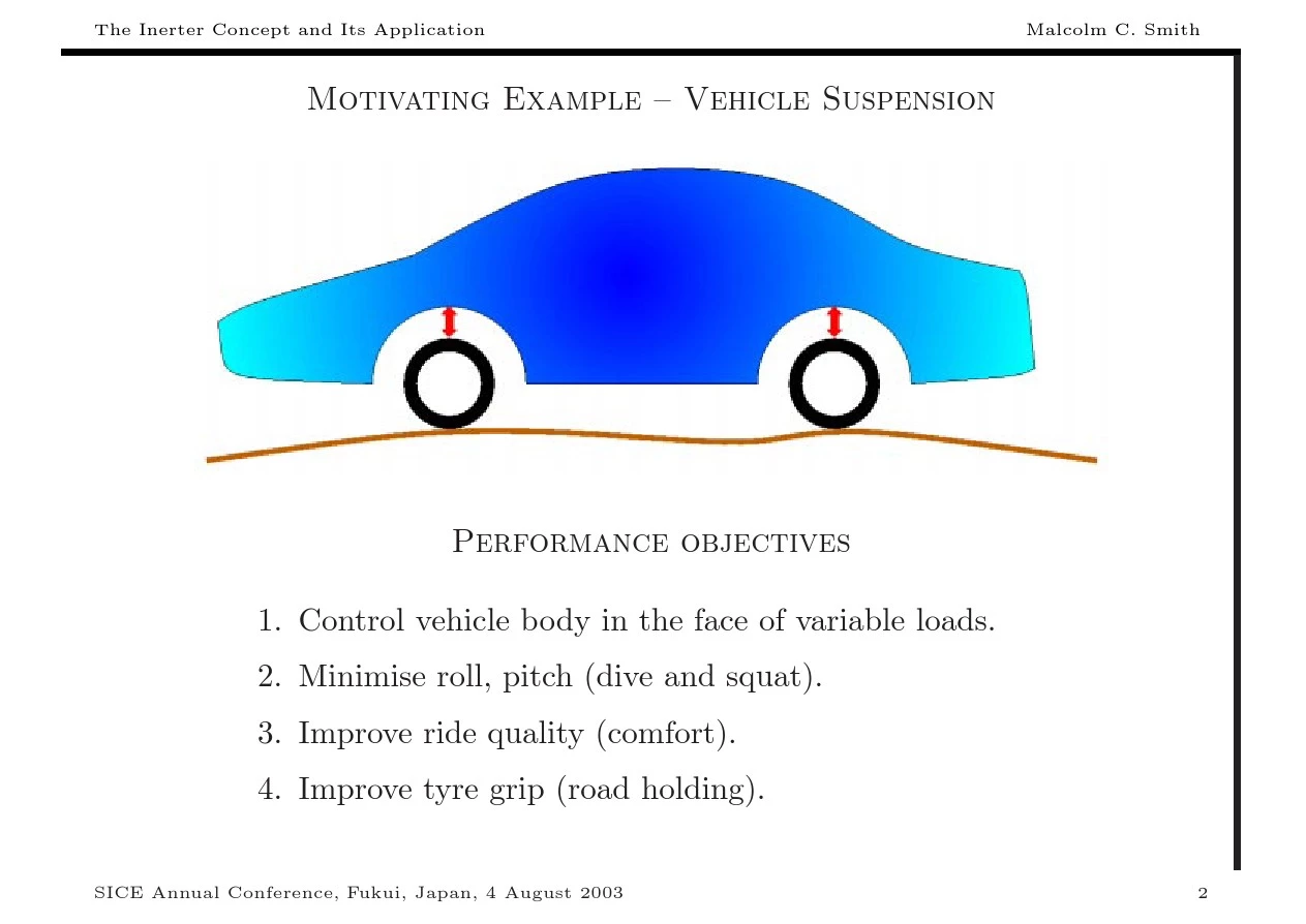
Motivating Example–Vehicle Suspension
Performance objectives
1.Control vehicle body in the face of variable loads.
2.Minimise roll,pitch(dive and squat).
3.Improve ride quality(comfort).
4.Improve tyre grip(road holding).
Types of suspensions
1.Passive.
2.Semi-active.
3.Self-levelling.
4.“Fully active”.
Constraints
1.Suspension de?ection—hard limit.
2.Actuator constraints(e.g.bandwidth).
3.Di?culty of measurement(e.g.absolute ride-height).
A Challenging set of Problems for the Designer
Quarter-car Vehicle
Model
suspension load
disturbances
road
disturbances
Equations of motion:m s ¨z s =F s ?u,m u ¨z
u =u +k t (z r ?z u ).
Invariant Equation
The following equation holds
m s¨z s+m u¨z u=F s+k t(z r?z u) independently of u.
This represents behaviour that the suspension designer cannot
Invariant Points
ω1=
m u
“tyre-hop”invariant frequency
For any suspension:
?z s
m s
Further Work
1.What is the complete freedom on a given transfer function?[1]
2.What is the minimum number of sensors required to achieve a given
behaviour?[1]
3.Are there conservation laws?[1]
4.Can disturbance paths for“ride”and“handling”be adjusted
independently?[2]
[1]M.C.Smith,Achievable dynamic response for automotive
active suspension,Vehicle System Dynamics,24(1995),pp.1–33.
[2]M.C.Smith and G.W.Walker,Performance limitations and
constraints for active and passive suspensions:a mechanical multi-
port approach,Vehicle System Dynamics,33(2000),pp.137–168.
Conservation
Laws
Area formula
Active Suspension Design
m s
(1)Modal Decomposition
(2)Decoupling of Ride
and Handling
Passive Suspensions(Abstract Approach)
Try to understand which vehicle dynamic behaviours are possible and which are not—without worrying initially how the behaviour is realised.
This is a black-box approach.
Classical electrical circuit theory should be applicable.
Driving-Point Impedance
?v(s)
Z(s)=
Classical Electrical Network Synthesis
De?nition.A network is passive if for all admissible v,i which are square integrable on(?∞,T],
T
v(t)i(t)dt≥0.
?∞
Theorem1.A network is passive if and only if Z(s)is positive-real,i.e.
0.
Z(s)is analytic and Re(Z(s))≥0in Re(s)>
Fundamental Theorem of Electrical Network Synthesis
Theorem2.Brune(1931),Bott-Du?n(1949).Any rational function which is positive-real can be realised as the driving-point impedance of an electrical network consisting of resistors,capacitors and inductors.
Positive
Real
Function
Circuit Realisation
Classic reference:E.A.Guillemin,Synthesis of Passive Networks,Wiley,1957.
Electrical-Mechanical Analogies
1.Force-Voltage Analogy.
voltage?force
current?velocity
Oldest analogy historically,cf.electromotive force.
2.Force-Current Analogy.
current?force
voltage?velocity
electrical ground?mechanical ground
Independently proposed by:Darrieus(1929),H¨a hnle(1932),Firestone(1933). Respects circuit“topology”,e.g.terminals,through-and across-variables.
Standard Element Correspondences(Force-Current Analogy)
v=Ri cv=F
v=L di inductor?spring
dt
F
=
C dv capacitor?mass
dt
The Exceptional Nature of the Mass Element
Newton’s Second Law gives the following network interpretation of the mass element:
?One terminal is the centre of mass,
?Other terminal is a?xed point in the inertial frame.
Hence,the mass element is analogous to a grounded capacitor.
Standard network symbol for the mass
element:
Table of usual
correspondences
Consequences for network synthesis
Two major problems with the use of the mass element for synthesis of “black-box”mechanical impedences:
?An electrical circuit with ungrounded capacitors will not have a direct mechanical analogue,
?Possibility of unreasonably large masses being required.
Question
Is it possible to construct a physical device such that
the relative acceleration between its endpoints is pro-
portional to the applied force?
One method of
realisation
1
r 1=radius of rack pinion γ=radius of gyration of ?ywheel r 2=radius of gear wheel m
=mass of the ?ywheel r 3
=radius of ?ywheel pinion α1=γ/r 3and α2=r 2/r 1
Equation of motion :
F =(m α21α2
2)(˙v 2?˙v 1)
(Assumes mass of gears,housing etc is negligible.)
The Ideal Inerter
We de?ne the Ideal Inerter
b(v2?v1)2.
2
The ideal inerter can be approximated in the same sense that real springs, dampers,inductors,etc approximate their mathematical ideals.
We can assume its mass is small.
M.C.Smith,Synthesis of Mechanical Networks:The Inerter,
IEEE Trans.on Automat.Contr.,47(2002),pp.1648–1662.
A new correspondence for network synthesis
k
b d(v2?v1)di
d(v2?v1)
1
impedance