
Example: Configuring Port Mirroring for Local Monitoring of Employee Resource Use on EX Series Switches
EX Series switches allow you to configure port mirroring to send copies of packets to either a local interface for local monitoring or to a VLAN for remote monitoring. You can use port mirroring to copy these packets:
?Packets entering or exiting a port
?Packets entering a VLAN on EX2200, EX3200, EX4200, or EX4500 switches
?Packets exiting a VLAN on EX8200 switches
You can analyze the mirrored traffic using a protocol analyzer application installed on
a system connected to the local destination interface (or a running on a remote
monitoring station if you are sending mirrored traffic to an analyzer VLAN).
This example describes how to configure an EX Series switch to mirror traffic
entering interfaces connected to employee computers to an analyzer output interface on the same switch.
This example describes how to configure local port mirroring:
Requirements
This example uses the following hardware and software components:
?Junos OS Release 9.0 or later for EX Series switches
?One EX Series switch
Before you configure port mirroring, be sure you have an understanding of port
mirroring concepts.
Overview and Topology
This topic includes two related examples that describe how to mirror traffic entering ports on the switch to a destination interface on the same switch. The first example shows how to mirror all traffic entering the ports connected to employee computers.
The second example shows the same scenario, but includes a filter to mirror only the employee traffic going to the Web.
In this example, ge-0/0/0 and ge-0/0/1 serve as connections for employee
computers.
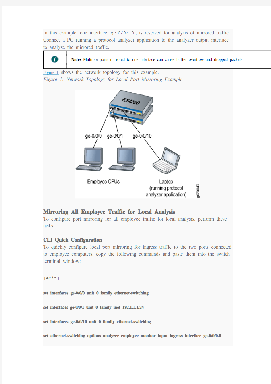
In this example, one interface, ge-0/0/10, is reserved for analysis of mirrored traffic. Connect a PC running a protocol analyzer application to the analyzer output interface
to analyze the mirrored traffic.
Note: Multiple ports mirrored to one interface can cause buffer overflow and dropped packets. Figure 1 shows the network topology for this example.
Figure 1: Network Topology for Local Port Mirroring Example
Mirroring All Employee Traffic for Local Analysis
To configure port mirroring for all employee traffic for local analysis, perform these tasks:
CLI Quick Configuration
To quickly configure local port mirroring for ingress traffic to the two ports connected
to employee computers, copy the following commands and paste them into the switch terminal window:
[edit]
set interfaces ge-0/0/0 unit 0 family ethernet-switching
set interfaces ge-0/0/1 unit 0 family inet 192.1.1.1/24
set interfaces ge-0/0/10 unit 0 family ethernet-switching
set ethernet-switching options analyzer employee–monitor input ingress interface ge-0/0/0.0
set ethernet-switching options analyzer employee–monitor input ingress interface ge-0/0/1.0
set ethernet-switching options analyzer employee–monitor output interface ge-0/0/10.0
Step-by-Step Procedure
To configure an analyzer called employee-monitor and specify the input (source) interfaces and the analyzer output interface:
1.Configure each interface connected to employee computers as an input interface for the port-mirror analyzer that
we are calling employee-monitor:
[edit ethernet-switching-options]
user@switch# set analyzer employee-monitor input ingress interface ge–0/0/0.0
user@switch# set analyzer employee-monitor input ingress interface ge–0/0/1.0
2.Configure the output analyzer interface for the employee-monitor analyzer. This will be the destination
interface for the mirrored packets:
[edit ethernet-switching-options]
user@switch# set analyzer employee-monitor output interface ge-0/0/10.0
Results
Check the results of the configuration:
[edit]user@switch# show ethernet-switching-options {analyzer
employee-monitor {input {ingress {interface ge-0/0/0.0;interface ge-0/0/1.0;}}output {interface {ge-0/0/10.0;}}}}
Mirroring Employee-to-Web Traffic for Local Analysis
To configure port mirroring for employee to web traffic, perform these tasks:
CLI Quick Configuration
To quickly configure local port mirroring of traffic from the two ports connected to employee computers, filtering so that only traffic to the external Web is mirrored, copy the following commands and paste them into the switch terminal window: [edit]
set ethernet-switching-options analyzer employee–web–monitor output interface ge-0/0/10.0
set firewall family ethernet-switching filter watch-employee term employee-to-corp from
destination-address 192.0.2.16/28
set firewall family ethernet-switching filter watch-employee term employee-to-corp from
source-address 192.0.2.16/28
set firewall family ethernet-switching filter watch-employee term employee-to-corp then accept
set firewall family ethernet-switching filter watch-employee term employee-to-web from
destination-port 80
set firewall family ethernet-switching filter watch-employee term employee-to-web then analyzer employee-web-monitor
set interfaces ge-0/0/0 unit 0 family ethernet-switching filter input watch-employee
set interfaces ge-0/0/1 unit 0 family ethernet-switching filter input watch-employee
Step-by-Step Procedure
To configure local port mirroring of employee-to-web traffic from the two ports
connected to employee computers:
1.Configure the local analyzer interface:
[edit interfaces]
user@switch# set ge-0/0/10 unit 0 family ethernet-switching
2.Configure the employee-web-monitor analyzer output (the input to the analyzer comes from the action of
the filter):
[edit ethernet-switching-options]
user@switch# set analyzer employee-web-monitor output interface ge-0/0/10.0
3.Configure a firewall filter called watch-employee to send mirrored copies of employee requests to the Web
to the employee-web-monitor analyzer. Accept all traffic to and from the corporate subnet (destination or source address of 192.0.2.16/28). Send mirrored copies of all packets destined for the Internet
(destination port 80) to the employee-web-monitor analyzer.
[edit firewall family ethernet-switching]
user@switch# set filter watch-employee term employee-to-corp from destination-address 192.0.2.16/28
user@switch# set filter watch-employee term employee-to-corp from source-address
192.0.2.16/28
user@switch# set filter watch-employee term employee-to-corp then accept
user@switch# set filter watch-employee term employee-to-web from destination-port 80
user@switch# set filter watch-employee term employee-to-web then analyzer
employee-web-monitor
4.Apply the watch-employee filter to the appropriate ports:
[edit interfaces]
user@switch# set ge-0/0/0 unit 0 family ethernet-switching filter input watch-employee
user@switch# set ge-0/0/1 unit 0 family ethernet-switching filter input watch-employee Results
Check the results of the configuration:
[edit]user@switch# show ethernet-switching-options {analyzer
employee-web-monitor {output {interface ge-0/0/10.0;}}}...firewall family ethernet-switching {filter watch-employee {term employee-to-corp {from {destination-address 192.0.2.16/28;source-address
192.0.2.16/28;}then accept {}term employee-to-web {from
{destination-port 80;}then analyzer
employee-web-monitor;}}}...interfaces {ge-0/0/0 {unit 0 {family ethernet-switching {port-mode trunk;vlan members [employee-vlan,
voice-vlan];filter {input watch-employee;}}}}ge-0/0/1 {family
ethernet-switching {filter {input watch-employee;}}}}
Verification
To confirm that the configuration is correct, perform these tasks:
Verifying That the Analyzer Has Been Correctly Created
Purpose
Verify that the analyzer named employee-monitor or employee-web-monitor has been created on the switch with the appropriate input interfaces, and appropriate output interface.
Action
You can verify the port mirror analyzer is configured as expected using the show analyzer command.
user@switch> show analyzer
Analyzer name : employee-monitor
Output interface : ge-0/0/10.0
Mirror ratio : 1
Loss priority : Low
Ingress monitored interfaces : ge-0/0/0.0
Ingress monitored interfaces : ge-0/0/1.0
Egress monitored interfaces : None
Meaning
This output shows that the employee-monitor analyzer has a ratio of 1 (mirroring every packet, the default setting), a loss priority of low (set this option to high only when the analyzer output is to a VLAN), is mirroring the traffic entering
the ge-0/0/0 and ge-0/0/1 interfaces, and sending the mirrored traffic to
the ge-0/0/10interface.
第12章交换机基本配置 交换机是局域网中最重要的设备,交换机是基于MAC来进行工作的。和路由器类似,交换机也有IOS,IOS的基本使用方法是一样的。本章将简单介绍交换的一些基本配置。关于VLAN和Trunk等将在后面章节介绍。 12.1 交换机简介 交换机是第2层的设备,可以隔离冲突域。交换机是基于收到的数据帧中的源MAC地址和目的MAC地址来进行工作的。交换机的作用主要有两个:一个是维护CAM(Conetxt Address Memory)表,该表是计算机的MAC地址和交换端口的映射表;另一个是根据CAM 来进行数据帧的转发。交换对帧的处理有3种:交换机收到帧后,查询CAM表,如果能查询到目的计算机所在的端口,并且目的计算机所在的端口不是交换接收帧的源端口,交换机将把帧从这一端口转发出去(Forward);如果该计算机所在的端口和交换机接收帧的源端口是同一端口,交换机将过滤掉该帧(Filter);如果交换机不能查询到目的计算机所在的端口,交换机将把帧从源端口以外的其他所有端口上发送出去,这称为泛洪(Flood),当交换机接收到的帧是广播帧或多播帧,交换机也会泛洪帧。 12.2 实验0:交换机基本配置 1.实验目的: 通过本实验,可以掌握交换机的基本配置这项技能。 2.实验拓扑 实验拓扑图如图12-2所示。 图12-2 实验1拓扑图 3.实验步骤 (1)步骤1:通过PC0以Console方式登录交换机Switch0. 注意配置PC0上的终端. 登录成功后, 通过PC0配置交换机Switch0的主机名 Switch>enable Switch#conf terminal
目录 交换机远程TELNET登录 (2) 交换机远程AUX口登录 (5) 交换机DEBUG信息开关 (6) 交换机SNMP配置 (9) 交换机WEB网管配置 (10) 交换机VLAN配置 (12) 端口的TRUNK属性配置(一) (14) 交换机端口TRUNK属性配置(二) (16) 交换机端口TRUNK属性配置(三) (18) 交换机端口HYBRID属性配置 (21) 交换机IP地址配置 (23) 端口汇聚配置 (25) 交换机端口镜像配置 (27) 交换机堆叠管理配置 (29) 交换机HGMP V1 管理配置 (31) 交换机集群管理(HGMP V2)配置 (33) 交换机STP配置 (34) 路由协议配置 (36) 三层交换机组播配置 (41) 中低端交换机DHCP-RELAY配置 (44) 交换机802.1X配置 (46) 交换机VRRP配置 (51) 单向访问控制 (54) 双向访问控制 (57) IP+MAC+端口绑定 (62) 通过ACL实现的各种绑定的配置 (64) 基于端口限速的配置 (66)
基于流限速的配置 (68) 其它流动作的配置 (70) 8016 交换机DHCP配置 (73)
. 交换机远程T ELNET 登录 1 功能需求及组网说明 2 telnet 配置 『配置环境参数 』 PC 机固定I P 地址10.10.10.10/24 SwitchA 为三层交换机,vlan100 地址10.10.10.1/24 SwitchA 与S witchB 互连v lan10 接口地址192.168.0.1/24 SwitchB 与S witchA 互连接口v lan100 接口地址192.168.0.2/24 交换机S witchA 通过以太网口e thernet 0/1 和S witchB 的e thernet0/24 实现互连。 『组网需求』 1. SwitchA 只能允许10.10.10.0/24 网段的地址的P C telnet 访问 2. SwitchA 只能禁止10.10.10.0/24 网段的地址的P C telnet 访问 3. SwitchB 允许其它任意网段的地址t elnet 访问 2 数据配置步骤 『PC 管理交换机的流程』 1. 如果一台P C 想远程T ELNET 到一台设备上,首先要保证能够二者之间正常通信。 SwitchA 为三层交换机,可以有多个三层虚接口,它的管理v lan 可以是任意一个 具有三层接口并配置了I P 地址的v lan 2. SwitchB 为二层交换机,只有一个二层虚接口,它的管理v lan 即是对应三层虚 接口并配置了I P 地址的v lan 3. Telnet 用户登录时,缺省需要进行口令认证,如果没有配置口令而通过T elnet 登录,则系统会提示“password required, but none set.”。 【SwitchA 相关配置】
实验2 交换机的端口配置与管理 实验目标 掌握交换机基本信息的配置管理。 实验背景 某公司新进一批交换机,在投入网络以后要进行初始配置与 管理,你作为网络管理员,对交换机进行端口的配置与管 理。 技术原理 交换机的管理方式基本分为两种:带内管理和带外管理。 通过交换机的Console端口管理交换机属于带外管理;这 种管理方式不占用交换机的网络端口,第一次配置交换机 必须利用Console端口进行配置。 交换机的命令行操作模式主要包括: 用户模式 Switch> 特权模式 Switch# 全局配置模式 Switch(config)# 端口模式 Switch(config-if)# 实验步骤: 新建Packet Tracer拓扑图 了解交换机端口配置命令行 修改交换机名称(hostname X) 配置交换机端口参数(speed,duplex) 查看交换机版本信息(show version) 查看当前生效的配置信息(show running-config) 查看保存在NVRAM中的启动配置信息(show startup- config) 查看端口信息 Switch#show interface 查看交换机的MAC地址表Switch#show mac-address-table 选择某个端口Switch(config)# interface type mod/port (type 表示端口类型,通常有ethernet、Fastethernet、 Gigabitethernet)(mod表示端口所在的模块,port表示在该 模块中的编号)例如interface fastethernet0/1 选择多个端口Switch(config)#interface type mod/startport- endport
常见几种交换机的镜像口配置方法 现在跑离线宾馆的时候,遇到问题最多的是网桥模式,而且一般小宾馆的路由器都不支持镜像功能,而有的宾馆的交换机却可以做镜像口。下面简单介绍了几种常见的交换机做镜像口地方法。 如果宾馆的交换机提供端口镜像功能,则允许管理人员自行设置一个监视管理端口来监视被监视端口的数据。监视到的数据可以通过我们设备来查看,通过对数据的分析就可以实时查看被监视端口的情况。如下图所示: 大多数三层交换机和部份两层交换机,具备端口镜像功能,不同的交换机或不同的型号,镜像配置方法的有些区别,下面我们提供常见交换机的镜像配置方法: Cisco CATALYST交换机端口监听配置 3COM交换机端口监听配置 DELL交换机端口监听配置 NetCore交换机端口监听配置 Intel交换机端口监听配置 Avaya交换机端口监听配置 华为交换机端口监听配置 Cisco CATALYST交换机端口监听配置 CISCO CATALYST交换机分为两种,在CATALYST家族中称监听端口为分析端口(a nalysis port)。 1、Catalyst 2900XL/3500XL/2950系列交换机端口监听配置(基于CLI) 以下命令配置端口监听: port monitor
例如,F0/1和F0/2、F0/5同属VLAN1,F0/1监听F0/2、F0/5端口: interface FastEthernet0/1 port monitor FastEthernet0/2 port monitor FastEthernet0/5 port monitor VLAN1 2、Catalyst 4000/5000/6000系列交换机端口监听配置(基于IOS) 以下命令配置端口监听: set span 例如,模块6中端口1和端口2同属VLAN1,端口3在VLAN2,端口4和5在VLA N2,端口2监听端口1和3、4、5,set span 6/1,6/3-5 6/2 注: 我们向正式用户提供更为详细的《Cisco IOS Software Configuration Guide》 如果您是我们的正式用户请与我们联系。 3COM交换机端口监听配置 在3COM交换机中,端口监听被称为“Roving Analysis”。网络流量被监听的端口称作“监听口”(Monitor Port),连接监听设备的端口称作“分析口”(Analyzer Port)。 以下命令配置端口监听: 指定分析口 feature rovingAnalysis add,或缩写f r a 例如: Select menu option: feature rovingAn alysis add Select analysis slot: 1 Select analysis port: 2 指定监听口并启动端口监听 feature rovingAnalysis start,或缩写f r sta 例如: Select menu option: feature rovingAn alysis start Select slot to monitor(1-12): 1 Select port to monitor&nb sp; (1-8): 3 停止端口监听
华为交换机端口镜像配置举例 配置实例 文章出处:https://www.doczj.com/doc/7816366605.html, 端口镜像是将指定端口的报文复制到镜像目的端口,镜像目的端口会接入数据监测设备,用户利用这些设备分析目的端口接收到的报文,进行网络监控和故障排除。本文介绍一个在华为交换机上通过配置端口镜像实现对数据监测的应用案例,详细的组网结构及配置步骤请查看以下内容。 某公司内部通过交换机实现各部门之间的互连,网络环境描述如下: 1)研发部通过端口Ethernet 1/0/1接入Switch C;λ 2)市场部通过端口Ethernet 1/0/2接入Switch C;λ 3)数据监测设备连接在Switch C的Ethernet 1/0/3端口上。λ 网络管理员希望通过数据监测设备对研发部和市场部收发的报文进行监控。 使用本地端口镜像功能实现该需求,在Switch C上进行如下配置: 1)端口Ethernet 1/0/1和Ethernet 1/0/2为镜像源端口;λ 2)连接数据监测设备的端口Ethernet 1/0/3为镜像目的端口。λ 配置步骤 配置Switch C: # 创建本地镜像组。
【实验文档】【实验0021】【交换机的端口安全配置】 【实验名称】 交换机的端口安全配置。 【实验目的】 掌握交换机的端口安全功能,控制用户的安全接入。 【背景描述】 你是一个公司的网络管理员,公司要求对网络进行严格控制。为了防止公司内部用户的IP 地址冲突,防止公司内部的网络攻击和破坏行为。为每一位员工分配了固定的IP地址,并且限制只允许公司员工主机可以使用网络,不得随意连接其他主机。例如:某员工分配的IP地址是172.16.1.55/24,主机MAC地址是00-06-1B-DE-13-B4。该主机连接在1台2126G 上边。 【技术原理】 交换机端口安全功能,是指针对交换机的端口进行安全属性的配置,从而控制用户的安全接入。交换机端口安全主要有两种类项:一是限制交换机端口的最大连接数,二是针对交换机端口进行MAC地址、IP地址的绑定。 限制交换机端口的最大连接数可以控制交换机端口下连的主机数,并防止用户进行恶意的ARP欺骗。 交换机端口的地址绑定,可以针对IP地址、MAC地址、IP+MAC进行灵活的绑定。可以实现对用户进行严格的控制。保证用户的安全接入和防止常见的内网的网络攻击。如ARP欺骗、IP、MAC地址欺骗,IP地址攻击等。 配置了交换机的端口安全功能后,当实际应用超出配置的要求,将产生一个安全违例,产生安全违例的处理方式有3种: ? protect 当安全地址个数满后,安全端口将丢弃未知名地址(不是该端口的安全地址中的任何一个)的包。 ? restrict 当违例产生时,将发送一个Trap通知。 ? shutdown 当违例产生时,将关闭端口并发送一个Trap通知。 当端口因为违例而被关闭后,在全局配置模式下使用命令errdisable recovery来将接口从错误状态中恢复过来。 【实现功能】 针对交换机的所有端口,配置最大连接数为1,针对PC1主机的接口进行IP+MAC地址绑定。【实验设备】 S2126G交换机(1台),PC(1台)、直连网线(1条)
华为交换机配置命令手 册及实验 Huawei 交换机配置命令手册: 1、开始 建立本地配置环境,将主机的串口通过配置电缆与以太网交换机的Console 口连接。在 主机上运行终端仿真程序(如Windows 的超级终端等),设置终端通信参数为:波特 率为9600bit/s、8 位数据位、1 位停止位、无校验和无流控,并选择终端类型为 VT100。 以太网交换机上电,终端上显示以太网交换机自检信息,自检结束后提示用户键入回车,之后将出现命令行提示符(如
(5)VLAN 接口视图(配置VLAN 和VLAN 汇聚对应的IP 接口参数)[Quidway-Vlan- interface1]:在系统视图下键入interface vlan-interface 123 (6)本地用户视图(配置本地用户参数)[Quidway-luser-user1]:在系统视图下键入 local- user user1 (7)用户界面视图(配置用户界面参数)[Quidway-ui0]:在系统视图下键入user-interface 3、其他命令 设置系统时间和时区
华为交换机各种配置实例[网管必学 交换机配置(一)端口限速基本配置 华为3Com 2000_EI、S2000-SI、S3000-SI、S3026E、S3526E、S3528、S3552、S3900、S3050、S5012、S5024、S5600系列: 华为交换机端口限速 2000_EI系列以上的交换机都可以限速! 限速不同的交换机限速的方式不一样! 2000_EI直接在端口视图下面输入LINE-RATE (4 )参数可选! 端口限速配置 1功能需求及组网说明 端口限速配置 『配置环境参数』 1. PC1和PC2的IP地址分别为10.10.1.1/24、10.10.1.2/24 『组网需求』 1. 在SwitchA上配置端口限速,将PC1的下载速率限制在3Mbps,同时将PC1的上传速率限制在1Mbps
2数据配置步骤 『S2000EI系列交换机端口限速配置流程』 使用以太网物理端口下面的line-rate命令,来对该端口的出、入报文进行流量限速。 【SwitchA相关配置】 1. 进入端口E0/1的配置视图 [SwitchA]interface Ethernet 0/1 2. 对端口E0/1的出方向报文进行流量限速,限制到3Mbps [SwitchA- Ethernet0/1]line-rate outbound 30 3. 对端口E0/1的入方向报文进行流量限速,限制到1Mbps [SwitchA- Ethernet0/1]line-rate inbound 16 【补充说明】 报文速率限制级别取值为1~127。如果速率限制级别取值在1~28范围内,则速率限制的粒度为64Kbps,这种情况下,当设置的级别为N,则端口上限制的速率大小为N*64K;如果速率限制级别取值在29~127范围内,则速率限制的粒度为1Mbps,这种情况下,当设置的级别为N,则端口上限制的速率大小为(N-27)*1Mbps。 此系列交换机的具体型号包括:S2008-EI、S2016-EI和S2403H-EI。
网络拓扑图如下: 根据图示连接设备。 在本次试验中,具体端口情况如上图数字标出。核心交换机(core )设置为s1或者SW1,汇聚层交换机(access)设置为s2或者SW2。 IP 地址分配: Router:e0::f0/1: 接口:Core vlan10: Vlan20: Vlan30: Access vlan10: Vlan20: Vlan30: 服务器IP地址:区域网段地址: PC1:PC2:路由器清空配置命令: en erase startup-config Reload 交换机清空配置命令: en erase startup-config
delete Reload 加速命令: en conf t no ip domain lookup line con 0 exec-timeout 0 0 logging syn hostname 一、OFFICE 区域地址静态分配,防止OFFICE 网络发生ARP 攻击,不允许OFFICE 网段PC 互访;STUDENTS 区域主机输入正确的学号和密码后接入网络,自动获取地址,阻止STUDENTS网段地址发生ARP攻击; 1、基本配置 SW1的配置: SW1(config)#vtp domain cisco 然后在pc上进入接口,设置为DHCP获取地址,命令如下: int f0/1 ip add dhcp 查看结果:
5、Student区域ARP防护: SW2配置如下: ip dhcp snooping //开启DHCP侦听 ip dhcp snooping vlan 20 int range f0/1,f0/2 ip dhcp snooping limit rate 5 //限制DHCP请求包数量,此处为5 ip verify source port-security exit int port-channel 10 ip dhcp snooping trust //设置信任端口 然后修改pc1的mac地址,就可以发现端口down状态,修改mac地址命令如下: pc1(config)#int e0/0 pc1(config-if)#mac-address 、AAA认证: 服务器地址为:vlan 30 //创建vlan 30的原因:在sw1、sw2中配置svi口,服务器的地址为,使他们位于同一个网段。这样pc机发出的认证数据包就会被发往服务器 s1(config-if)#ip add f0/5 s1(config-if)#switchport mode access s1(config-if)#switchport access vlan 30 s2(config)#int vlan 30 s2(config-if)#ip add new-model //AAA配置位于接入层交换机,所以核心交换机sw1连接服务器的接口不需要配置IP地址 s2(config)#aaa authentication login vtylogin group radius s2(config)#radius-server host auth-port 1812 acct
华为S5700交换机端口镜像该怎么配置交换机的主要功能包括物理编址、网络拓扑结构、错误校验、帧序列以及流控。交换机还具备了一些新的功能,如对V L A N(虚拟局域网)的支持、对链路汇聚的支持,甚至有的还具有防火墙的功能。那么华为S5700交换机配置怎么端口镜像?其实不难,我们需要先知道原理。下面一起看看! 方法步骤 1、演示环境中是通过电脑的c o m接口连接华为交换机的,你也可以通过t e l n e t来操作 2、先确认你电脑的c o m接口编号 3、然后运行超级终端工具 4、选择你电脑的c o m接口编号 5、设置比特率 6、成功登陆交换机 7、在系统视图下配置端口镜像 先配置观察端口 [Q u i d w a y]o b s e r v e-p o r t1i n t e r f a c e G i g a b i t E t h e r n e t0/0/24 8、然后再进入需要镜像的端口
[Q u i d w a y]i n t e r f a c e G i g a b i t E t h e r n e t0/0/23 9、在配置镜像端口模式 [Q u i d w a y-G i g a b i t E t h e r n e t0/0/23]p o r t-m i r r o r i n g t o o b s e r v e-p o r t1b o t h 10、配置完成之后用d i s p l a y c u r r e n t查看下配置 11、剩下的就是你吧电脑接入到24端口来观察23端口的数据了 补充:交换机基本使用方法 作为基本核心交换机使用,连接多个有线设备使用:网络结构如下图,基本连接参考上面的 作为网络隔离使用:对于一些功能好的交换机,可以通过模式选择开关选择网络隔离模式,实现网络隔离的作用,可以只允许普通端口和U P l i n k端口通讯,普 通端口之间是相互隔离不可以通讯的 除了作为核心交换机(中心交换机)使用,还可以作为扩展交换机(接入交换机)来扩展网络 放在路由器上方,扩展网络供应商的网络线路(用于一条线路多个I P的网络),连接之后不同的路由器用不同的I P连接至公网
实验三 交换机基本配置及交换机端口配置(3学时) 一、 实验目的: 1. 熟悉并掌握交换机的命令行视图。 2. 要求熟练掌握交换机的基本配置方法,能完成日常管理网络或配置网络 中有关交换机端口的常用配置,并逐步熟悉交换机端口的基本信息。 3. 掌握用console 端口配置交换机的方法。 4. 掌握在交换机端口视图下对交换机的端口的各参数进行配置和管理。 二、 实验设备: 1. 交换机 2. 计算机、网卡 3. 网线 4. 串口线 三、 实验内容及实验步骤: (一) 交换机的初步认识 Quidway S3526 以太网交换机是华为公司推出的盒式L2/L3 层线速以太网交换产品。 图1 Quidway S3526交换机外观
图2 S3526 交换机交流机箱后面板示意图 图3 S3526 交换机直流机箱后面板示意图表1 S3526 交换机前面板指示灯 表2 配置口(Console)属性
(二) 交换机的电缆连接(通过Console 口搭建本地配置环境) 【备注】:交换机的配置环境可通过Console 口搭建本地配置环境、通过Telnet 搭建配置环境、通过Modem 拨号搭建配置环境(参见S3500操作手册1入门操作.PDF 文档说明,本实验主要通过Console 口搭建本地配置环境) 需要连接3根线:①电源线;② 网线;③配置电缆。如图连接方式: (三) 交换机的启动 ①电源线 连接到插座 连接到交换机电源插口
1.点击“开始”-“程序”-“附件”-“通讯”-“超级终端”进行交换机的连接与串口参数设置: 图5 超级终端连接说明界面 图6 超级终端连接使用串口设置
H3C交换机流量镜像 2013-11-01 08:57:50 我来说两句作者:Eliot 收藏我要投稿H3C交换机流量镜像 今天需要对交换机进行本地流量镜像,在此记录: 交换机:H3C S5120 配置本地端口镜像时,用户首先要创建一个本地镜像组,然后为本地镜像组配置源端口和目的端口。 表1-1 配置本地端口镜像 操作 命令 说明 进入系统视图 system-view - 创建本地镜像组 mirroring-group group-id local 必选 为镜像组配置源端口
在系统视图下配置源端口 mirroring-group group-id mirroring-port mirroring-port-list { both | inbound |outbound } 必选 用户可以在系统视图下同时配置多个源端口,也可以在具体的端口视图下配置源端口,两种视图下的配置效果相同 在端口视图下配置源端口 interface interface-type interface-number [ mirroring-group group-id ] mirroring-port { both | inbound | outbound } quit 为镜像组配置目的端口 在系统视图下配置目的端口 mirroring-group group-id monitor-portmonitor-port-id 二者必选其一 两种视图下的配置效果相同 在端口视图下配置目的端口 interface interface-type interface-number
[ mirroring-group group-id ] monitor-port l 本地镜像组需要配置源端口、目的端口才能生效。 l 一个镜像组中可以配置多个源端口,但只能配置一个目的端口。 l 一个端口只能被一个镜像组使用。 l 建议用户不要在目的端口上使能STP、MSTP和RSTP,否则会影响设备的正常使用。 l 目的端口收到的报文包括复制自源端口的报文和来自其它端口的正常转发报文。为了保证数据监测设备只对源端口的报文进行分析,建议目的端口仅用于端口镜像,不用做其它用途。 1、使用PC连接Console端口,与交换机建立连接。 2、在Win7可以下载一个超级终端Hyper Terminal [plain] system-view //进入系统视图 #display mac-address //显示mac地址列表。如果不知道网口对应的交换器端口,通过mac地址列表可以获得 # 创建本地镜像组。 mirroring-group 1 local # 为本地镜像组配置源端口和目的端口。 mirroring-group 1 mirroring-port gigabitethernet 1/0/22 both mirroring-group 1 monitor-port gigabitethernet 1/0/13 # 显示所有镜像组的配置信息。 display mirroring-group all 如果想修改镜像的源端口或者目的端口,使用undo指令,然后重新添加。例如修改镜像源端口为1/0/21
【官方提供】【实验文档】【实验0021】【交换机的端口安全配置】 【实验名称】 交换机的端口安全配置。 【实验目的】 掌握交换机的端口安全功能,控制用户的安全接入。 【背景描述】 你是一个公司的网络管理员,公司要求对网络进行严格控制。为了防止公司内部用户的IP 地址冲突,防止公司内部的网络攻击和破坏行为。为每一位员工分配了固定的IP地址,并且限制只允许公司员工主机可以使用网络,不得随意连接其他主机。例如:某员工分配的IP地址是172.16.1.55/24,主机MAC地址是00-06-1B-DE-13-B4。该主机连接在1台2126G 上边。 【技术原理】 交换机端口安全功能,是指针对交换机的端口进行安全属性的配置,从而控制用户的安全接入。交换机端口安全主要有两种类项:一是限制交换机端口的最大连接数,二是针对交换机端口进行MAC地址、IP地址的绑定。 限制交换机端口的最大连接数可以控制交换机端口下连的主机数,并防止用户进行恶意的ARP欺骗。 交换机端口的地址绑定,可以针对IP地址、MAC地址、IP+MAC进行灵活的绑定。可以实现对用户进行严格的控制。保证用户的安全接入和防止常见的内网的网络攻击。如ARP欺骗、IP、MAC地址欺骗,IP地址攻击等。 配置了交换机的端口安全功能后,当实际应用超出配置的要求,将产生一个安全违例,产生安全违例的处理方式有3种: ? protect 当安全地址个数满后,安全端口将丢弃未知名地址(不是该端口的安全地址中的任何一个)的包。 ? restrict 当违例产生时,将发送一个Trap通知。 ? shutdown 当违例产生时,将关闭端口并发送一个Trap通知。 当端口因为违例而被关闭后,在全局配置模式下使用命令errdisable recovery来将接口从错误状态中恢复过来。 【实现功能】 针对交换机的所有端口,配置最大连接数为1,针对PC1主机的接口进行IP+MAC地址绑定。【实验设备】 S2126G交换机(1台),PC(1台)、直连网线(1条)
实验1 交换机端口的基本配置 一、实验目的 1、练习cisco 交换机端口的基本配置 二、实验器材 实验环境:packet tracer 5.0 2、网络拓扑图如下图所示: 3、三、基本命令 以下为思科交换机基本命令详解以及图示 从用户模式进入进入特权模式 Enable 修改交换机名称 Hostname name 进入配置模式: Configure terminal(可简写为config t) 显示当前活动的交换机配置文件 Show running-config
下列命令可以用于显示接口1 的统计和状态信息Show interface f0/1
查看vlan 信息 Show vlan 其中vlan1 是默认的管理vlan,未对交换机进行配置时所有的接口默认属于vlan1 查看flash 缓存内容 Show
flash 由上图可以看到flash 缓存中只有一个文件 查看IOS 版本号以及系统硬件的配置情况、引导镜像等(注:IOS—cisco 网络设备的操作系统) 从上图可以得知,IOS 版本为12.1,交换机已经运行25 分钟,共有24 个快速以太网接口,2 个千兆以太网接口。 恢复交换机到默认设置: Erase startup-config /删除备份配置文件 Reload /重新启动交换机
配置主机名称和控制端密码:Hostname snnumis0601 Line console 0 Passwod 123456 Login Line vty 0 15 Password 123456 Login 为二层交换机设置管理vlan 与默认网关Interface vlan 1 Ip add 192.168.30.1 255.255.255.0 No shutdown Exit Ip default-gateway 192.168.30.254 Exit
适用场景:1-24口下联P C用户,25口下联二层网管交换机,26口上联汇聚交换机 堆叠环境中,若未指定优先级,则是根据它们的MAC地址(mac小的为主机)来确定谁是主机。优先级为越大越好,范围1-10。出场默认为1。 1、系统时间同步:如果客户有使用 ntp/sntp进行全网统一的时间配置的需求,可在设备上做Ruijie(config)#hostname TSG#5750 //给交换机命名 Ruijie(config)#sntp enable //首先开启 sntp 服务 Ruijie(config)#sntp server 210.72.145.44 //配置服务器IP地址,此为国家授时中心服务器IP 地址 Ruijie(config)#sntp interval 36000 // 配置sntp交互的时间间隔 措施一:限制远程管理源地址 Ruijie(config)#access-list 99 permit host 192.168.1.100 //配置控制列表,严格限定允许ip Ruijie(config)#line vty 0 35 Ruijie(config-line)#access-class 99 in 措施二:限制SNMP管理源地址 Ruijie(config)#access-list 99 permit host 192.168.1.100 //配置控制列表,严格限定允许ip Ruijie(config)#snmp-server community ruijie rw 99 措施三:使用加密管理协议,使用SSH管理,禁用Telnet协议 Ruijie(config)#no enable service telnet-server //禁用telnet管理 Ruijie(config)#enable service ssh-server //启用SSH管理 Ruijie(config)#crypto key generate dsa //设置ssh加密模式
关于华为各种型号交换机端口镜像配置方法总结 2007年03月25日星期日上午01:51 一、端口镜像概念: Port Mirror(端口镜像)是用于进行网络性能监测。可以这样理解:在端口A和端口B之间建立镜像关系,这样,通过端口A传输的数据将同时复制到端口B,以便于在端口B上连接的分析仪或者分析软件进行性能分析或故障判断。 二、端口镜像配置 『环境配置参数』 1.PC1接在交换机E0/1端口,IP地址1.1.1.1/24 2.PC2接在交换机E0/2端口,IP地址2.2.2.2/24 3.E0/24为交换机上行端口 4.Server接在交换机E0/8端口,该端口作为镜像端口 『组网需求』 1.通过交换机端口镜像的功能使用server对两台pc的业务报文进行监控。 2.按照镜像的不同方式进行配置: 1)基于端口的镜像 2)基于流的镜像 2数据配置步骤 『端口镜像的数据流程』 基于端口的镜像是把被镜像端口的进出数据报文完全拷贝一份到镜像端口,这样来进行流量观测或者故障定位。 【3026等交换机镜像】 S2008/S2016/S2026/S2403H/S3026等交换机支持的都是基于端口的镜像,有两种方法: 方法一 1.配置镜像(观测)端口
[SwitchA]monitor-port e0/8 2.配置被镜像端口 [SwitchA]port mirror Ethernet0/1to Ethernet0/2 方法二 1.可以一次性定义镜像和被镜像端口 [SwitchA]port mirror Ethernet0/1to Ethernet0/2observing-port Ethernet 0/8 【8016交换机端口镜像配置】 1.假设8016交换机镜像端口为E1/0/15,被镜像端口为E1/0/0,设置端口 1/0/15为端口镜像的观测端口。 [SwitchA]port monitor ethernet1/0/15 2.设置端口1/0/0为被镜像端口,对其输入输出数据都进行镜像。 [SwitchA]port mirroring ethernet1/0/0both ethernet1/0/15 也可以通过两个不同的端口,对输入和输出的数据分别镜像 1.设置E1/0/15和E2/0/0为镜像(观测)端口 [SwitchA]port monitor ethernet1/0/15 2.设置端口1/0/0为被镜像端口,分别使用E1/0/15和E2/0/0对输入和输出数据进行镜像。 [SwitchA]port mirroring gigabitethernet1/0/0ingress ethernet1/0/15 [SwitchA]port mirroring gigabitethernet1/0/0egress ethernet2/0/0 『基于流镜像的数据流程』 基于流镜像的交换机针对某些流进行镜像,每个连接都有两个方向的数据流,对于交换机来说这两个数据流是要分开镜像的。
端口镜像配置命令 1.1 端口镜像配置命令 1.1.1 display mirroring-group 【命令】 display mirroring-group { group-id| all | local | remote-destination | remote-source } 【视图】 任意视图 【参数】 group-id:端口镜像组的组号,取值范围为1~2。 all:所有镜像组。 local:本地镜像组。 remote-destination:远程目的镜像组。 remote-source:远程源镜像组。 【描述】 display mirroring-group命令用来显示端口镜像组的信息。 不同的镜像组类型,其显示内容不同。设备将按照镜像组号的顺序进行显示。【举例】 # 显示所有镜像组的信息。
monitor port: Ethernet1/0/3 mirroring-group 2: type: remote-source status: inactive mirroring port: Ethernet1/0/4 inbound reflector port: remote-probe vlan: 1900 表1-1 display mirroring-group命令显示信息描述表 1.1.2 mirroring-group 【命令】 mirroring-group group-id{ local | remote-source | remote-destination } undo mirroring-group{ group-id|local | remote-source|remote-destination | all } 【视图】 系统视图 【参数】 group-id:端口镜像组的组号,取值范围为1~2。
华为交换机交换机端口镜像配置 一、说明 『环境配置参数』 1. PC1接在交换机E0/1端口,IP地址1.1.1.1/24 2. PC2接在交换机E0/2端口,IP地址2.2.2.2/24 3. E0/24为交换机上行端口 4. Server接在交换机E0/8端口,该端口作为镜像端口 『组网需求』 1. 通过交换机端口镜像的功能使用server对两台pc的业务报文进行监控。 2. 按照镜像的不同方式进行配置: 1) 基于端口的镜像 2) 基于流的镜像 二、数据配置步骤『端口镜像的数据流程』 基于端口的镜像是把被镜像端口的进出数据报文完全拷贝一份到镜像端口,这样来进行流量观测或者故障定位。 【3026等交换机镜像】 S2008/S2016/S2026/S2403H/S3026等交换机支持的都是基于端口的镜像,有两种方法: 方法一 1. 配置镜像(观测)端口 [SwitchA]monitor-port e0/8 2. 配置被镜像端口 [SwitchA]port mirror Ethernet 0/1 to Ethernet 0/2 方法二 1. 可以一次性定义镜像和被镜像端口 [SwitchA]port mirror Ethernet 0/1 to Ethernet 0/2 observing-port Ethernet 0/8 【8016交换机端口镜像配置】 1. 假设8016交换机镜像端口为E1/0/15,被镜像端口为E1/0/0,设置端口1/0/15为端口镜像的观测端口。 [SwitchA] port monitor ethernet 1/0/15 2. 设置端口1/0/0为被镜像端口,对其输入输出数据都进行镜像。 [SwitchA] port mirroring ethernet 1/0/0 both ethernet 1/0/15 也可以通过两个不同的端口,对输入和输出的数据分别镜像 1. 设置E1/0/15和E2/0/0为镜像(观测)端口
实验一交换机的基本配置方法 一. 实验目的: 1. 掌握交换机常用配置方法 2. 掌握中低端交换机的基本命令行 二.实验设备 华为交换机3台,计算机3台 三. 实验内容及步骤: (一)以太网交换机基础 以太网的最初形态就是在一段同轴电缆上连接多台计算机,所有计算机都共享这段电缆。所以每当某台计算机占有电缆时,其他计算机都只能等待。这种传统的共享以太网极大的受到计算机数量的影响。为了解决上述问题,我们可以做到的是减少冲突域中的主机数量,这就是以太网交换机采用的有效措施。 以太网交换机在数据链路层进行数据转发时需要确认数据帧应该发送到哪一端口,而不是简单的向所有端口转发,这就是交换机MAC 地址表的功能。 以太网交换机包含很多重要的硬件组成部分:业务接口、主板、CPU、内存、Flash、电源系统。以太网交换机的软件主要包括引导程序和核心操作系统两部分。 (二)以太网交换机配置方式 以太网交换机的配置方式很多,如本地Console 口配置,Telnet 远程登陆配置,FTP、TFTP 配置和哑终端(TTY teletypewriter的缩写)方式配置。其中最为常用的配置方式就是Console 口配置和Telnet 远程配置。 注意:第一次进行交换机、路由器配置时必须使用Console本地配置。 1.通过Console口搭建配置环境 第一步:如图所示,建立本地配置环境,只需将微机(或终端)的串口通过配置电缆与以太网交换机的Console口连接。 第二步:在微机上运行终端仿真程序(如Windows 3.X的Terminal或Windows 9X的超级终端等),设置终端通信参数为:波特率为9600bit/s、8位数据位、1位停止位、无校验和无流控,如图所示。 第三步:以太网交换机加电,终端上显示以太网交换机自检信息,自检结束后提示用户