T-13/4 (5 mm) Precision Optical Performance AlInGaP LED Lamps
Data Sheet
Features
? Well Defined Spatial Radiation Patterns
? Viewing Angles: 6°, 15°, 23°, 30°
? High Luminous Output
? Colors:
590 nm Amber
605 nm Orange
615 nm Reddish-Orange
626 nm Red
? High Operating Temperature: T J LED=+130°C
? Superior Resistance to Moisture
? Package Options:
With or Without Lead Stand-Offs
Benefits
? Viewing Angles Match Traffic Management Sign Requirements
? Colors Meet Automotive and Pedestrian Signal Specifications
? Superior Performance in Outdoor Environments
? Suitable for Autoinsertion onto PC Boards Applications
? Traffic Management:
Traffic Signals
Pedestrian Signals
Work Zone Warning Lights
Variable Message Signs
? Commercial Outdoor
Advertising:
Signs
Marquees
? Automotive:
Exterior and Interior Lights
Description
These Precision Optical Perform-
ance AlInGaP LEDs provide
superior light output for
excellent readability in sunlight
and are extremely reliable.
AlInGaP LED technology
provides extremely stable light
output over long periods of time.
Precision Optical Performance
lamps utilize the aluminum
indium gallium phosphide
(AlInGaP) technology.
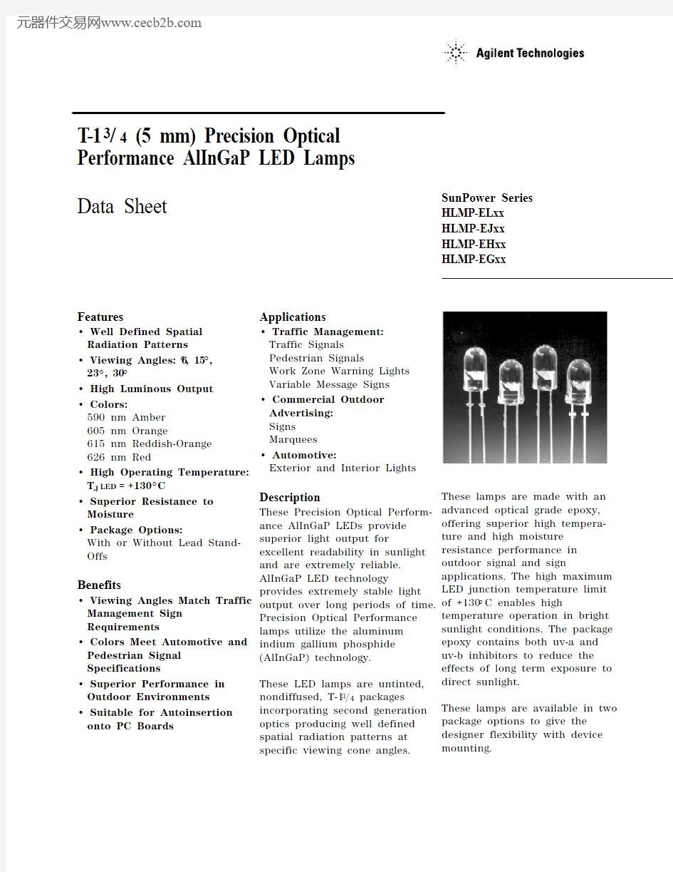
These LED lamps are untinted,
nondiffused, T-13/4 packages
incorporating second generation
optics producing well defined
spatial radiation patterns at
specific viewing cone angles.
SunPower Series
HLMP-ELxx
HLMP-EJxx
HLMP-EHxx
HLMP-EGxx
These lamps are made with an
advanced optical grade epoxy,
offering superior high tempera-
ture and high moisture
resistance performance in
outdoor signal and sign
applications. The high maximum
LED junction temperature limit
of +130°C enables high
temperature operation in bright
sunlight conditions. The package
epoxy contains both uv-a and
uv-b inhibitors to reduce the
effects of long term exposure to
direct sunlight.
These lamps are available in two
package options to give the
designer flexibility with device
mounting.
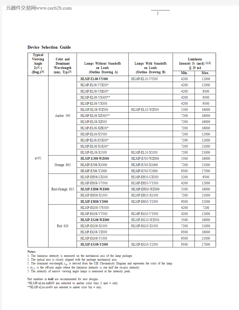
Device Selection Guide
Typical
Viewing Color and Luminous Angle Dominant Lamps Without Standoffs Lamps With Standoffs Intensity Iv (mcd) [1,2] 2θ1/2Wavelength on Leads on Leads@ 20 mA (Deg.)[4](nm), Typ.[3] (Outline Drawing A)(Outline Drawing B)Min.Max.
HLMP-EL08-VY000HLMP-EL10-VY000420012000
HLMP-EL08-VYK00*420012000
HLMP-EL08-VXK00*42009300
HLMP-EL08-VX400**42009300
HLMP-EL08-VX00042009300
HLMP-EL08-WZ000HLMP-EL10-WZ000550016000 Amber 590HLMP-EL08-XZ400**720016000
HLMP-EL08-XZ000720016000
HLMP-EL08-XZK00*720016000
HLMP-EL08-XY000720012000
HLMP-EL08-XYK00*720012000
HLMP-EL08-X1K00*720021000
HLMP-EL08-X1000HLMP-EL10-X1000720021000 6°[5]HLMP-EJ08-WZ000HLMP-EJ10-WZ000550016000 Orange 605HLMP-EJ08-X1000HLMP-EJ10-X1000720021000
HLMP-EJ08-Y2000HLMP-EJ10-Y2000930027000
HLMP-EH08-UX000HLMP-EH10-UX00032009300
HLMP-EH08-VY000HLMP-EH10-VY000420012000 Red-Orange 615HLMP-EH08-WZ000HLMP-EH10-WZ000550016000
HLMP-EH08-X1000HLMP-EH10-X1000720021000
HLMP-EH08-Y2000HLMP-EH10-Y2000930021000
HLMP-EG08-VW00042007200
HLMP-EG08-VY000HLMP-EG10-VY000420012000
HLMP-EG08-WZ000HLMP-EG10-WZ000550016000 Red 626HLMP-EG08-X1000HLMP-EG10-X1000720021000
HLMP-EG08-YZ000930016000
HLMP-EG08-Y1000930021000
HLMP-EG08-Y2000HLMP-EG10-Y2000930027000 Notes:
1. The luminous intensity is measured on the mechanical axis of the lamp package.
2. The optical axis is closely aligned with the package mechanical axis.
3. The dominant wavelength, λd, is derived from the CIE Chromaticity Diagram and represents the color of the lamp.
4. θ1/2 is the off-axis angle where the luminous intensity is one half the on-axis intensity.
5.The intensity of narrow viewing angle lamps is measured at the intensity peak.
Part numbers in bold are recommended for new designs.
*HLMP-xLxx-xxK00 are selected to amber color bins 2 and 4 only.
Device Selection Guide (Continued)
Typical
Viewing Color and Luminous Angle Dominant Lamps Without Standoffs Lamps With Standoffs Intensity Iv (mcd) [1,2] 2θ1/2Wavelength on Leads on Leads@ 20 mA (Deg.)[4](nm), Typ.[3] (Outline Drawing A)(Outline Drawing B)Min.Max.
HLMP-EL15-PS000HLMP-EL17-PS0008802500
HLMP-EL15-QR00011501900
HLMP-EL15-QRK00*11501900
HLMP-EL15-QS00011502500
HLMP-EL15-QS400**11502500
HLMP-EL15-QSK00*11502500
HLMP-EL15-QT000HLMP-EL17-QT00011503200
HLMP-EL15-QTK00*11503200
HLMP-EL15-RU000HLMP-EL17-RU00015004200
HLMP-EL17-SV00019005500 Amber 590HLMP-EL15-TW000HLMP-EL17-TW00025007200
HLMP-EL15-TWK00*25007200
HLMP-EL15-TUK00*25004200 15°HLMP-EL15-TV400**25005500
HLMP-EL15-UX000HLMP-EL17-UX00032009300
HLMP-EL15-VY000HLMP-EL17-VY000420012000
HLMP-EL15-VYK00*420012000
HLMP-EL15-VX00042009300
HLMP-EL15-VXK00*42009300
HLMP-EL15-VX400**42009300
HLMP-EL15-VW000*42007200
HLMP-EL15-VWK00*42007200
HLMP-EJ15-PS0008802500 Orange 605HLMP-EJ15-RU000HLMP-EJ17-RU00015004200
HLMP-EJ15-SV000HLMP-EJ17-SV00019005500
HLMP-EH15-QT000HLMP-EH17-QT00011503200 Red-Orange 615HLMP-EH15-RU000HLMP-EH17-RU00015004200
HLMP-EH15-TW000HLMP-EH17-TW00025007200
HLMP-EH15-UX000HLMP-EH17-UX00032009300 Notes:
1. The luminous intensity is measured on the mechanical axis of the lamp package.
2. The optical axis is closely aligned with the package mechanical axis.
3. The dominant wavelength, λd, is derived from the CIE Chromaticity Diagram and represents the color of the lamp.
4. θ1/2 is the off-axis angle where the luminous intensity is one half the on-axis intensity.
5.The intensity of narrow viewing angle lamps is measured at the intensity peak.
Part numbers in bold are recommended for new designs.
Device Selection Guide (Continued)
Typical
Viewing Color and Luminous Angle Dominant Lamps Without Standoffs Lamps With Standoffs Intensity Iv (mcd) [1,2] 2θ1/2Wavelength on Leads on Leads @ 20 mA (Deg.)[4](nm), Typ.[3](Outline Drawing A)(Outline Drawing B) Min.Max.
HLMP-EG15-PS0008802500
HLMP-EG15-QT000HLMP-EG17-QT00011503200 15°Red 626HLMP-EG15-RU000HLMP-EG17-RU00015004200
HLMP-EG15-UX000HLMP-EG17-UX00032009300
HLMP-EG15-TW000HLMP-EG17-TW00025007200
HLMP-EL24-MQ0005201500
HLMP-EL24-NR000HLMP-EL26-NR0006801900
HLMP-EL24-PS000HLMP-EL26-PS0008802500
HLMP-EL24-PSK00*8802500
HLMP-EL24-PR400**8801900
HLMP-EL24-PQK00*8801500
HLMP-EL24-QR00011501900
HLMP-EL24-QRK00*11501900
HLMP-EL24-QS00011502500
HLMP-EL24-QSK00*11502500
HLMP-EL24-QS400**11502500 23°Amber 590HLMP-EL24-QT000HLMP-EL26-QT00011503200
HLMP-EL24-QTK00*11503200
HLMP-EL24-RU000HLMP-EL26-RU00015004200
HLMP-EL24-RUK00*15004200
HLMP-EL26-SV00019005500
HLMP-EL24-STK00*19003200
HLMP-EL24-SUK00*19004200
HLMP-EL24-SU400**19004200
HLMP-EL24-SV00019005500
HLMP-EL24-SVK00*19005500
HLMP-EL24-TW000HLMP-EL26-TW00025007200
HLMP-EL24-TWK00*25007200 Notes:
1. The luminous intensity is measured on the mechanical axis of the lamp package.
2. The optical axis is closely aligned with the package mechanical axis.
3. The dominant wavelength, λd, is derived from the CIE Chromaticity Diagram and represents the color of the lamp.
4. θ1/2 is the off-axis angle where the luminous intensity is one half the on-axis intensity.
5.The intensity of narrow viewing angle lamps is measured at the intensity peak.
Part numbers in bold are recommended for new designs.
*HLMP-xLxx-xxK00 are selected to amber color bins 2 and 4 only.
Device Selection Guide (Continued)
Typical
Viewing Color and Luminous Angle Dominant Lamps Without Standoffs Lamps With Standoffs Intensity Iv (mcd) [1,2] 2θ1/2Wavelength on Leads on Leads@ 20 mA (Deg.)[4](nm), Typ.[3] (Outline Drawing A)(Outline Drawing B)Min.Max.
Orange 605HLMP-EJ24-QT000HLMP-EJ26-QT00011503200
HLMP-EJ24-RU000HLMP-EJ26-RU00015004200
HLMP-EH26-PS0008802500 Red-Orange 615HLMP-EH24-QT000HLMP-EH26-QT00011503200 23oHLMP-EH24-RU000HLMP-EH26-RU00015004200
HLMP-EH24-SV000HLMP-EH26-SV00019005500
HLMP-EG24-PS000HLMP-EG26-PS0008802500 Red 626HLMP-EG24-QT000HLMP-EG26-QT00011503200
HLMP-EG24-RU000HLMP-EG26-RU00015004200
HLMP-EL30-MQ000HLMP-EL32-MQ0005201500
HLMP-EL30-NR000HLMP-EL32-NR0006801900
HLMP-EL30-PQ0008801500
HLMP-EL30-PQK00*8801500
HLMP-EL30-PR0008801900
HLMP-EL30-PR400**8801900
HLMP-EL30-PRK00*8801900
HLMP-EL30-PS000HLMP-EL32-PS0008802500 30°Amber 590HLMP-EL30-PSK00*8802500
HLMP-EL30-QRK00*11501900
HLMP-EL30-QS00011502500
HLMP-EL30-QS400**11502500
HLMP-EL30-QT000HLMP-EL32-QT00011503200
HLMP-EL30-QTK00*11503200
HLMP-EL30-ST00019003200
HLMP-EL30-SU00019004200
HLMP-EL30-SU400**19004200
HLMP-EL30-SUK00*19004200 Notes:
1. The luminous intensity is measured on the mechanical axis of the lamp package.
2. The optical axis is closely aligned with the package mechanical axis.
3. The dominant wavelength, λd, is derived from the CIE Chromaticity Diagram and represents the color of the lamp.
4. θ1/2 is the off-axis angle where the luminous intensity is one half the on-axis intensity.
5.The intensity of narrow viewing angle lamps is measured at the intensity peak.
Part numbers in bold are recommended for new designs.
*HLMP-xLxx-xxK00 are selected to amber color bins 2 and 4 only.
**HLMP-xLxx-xx400 are selected to amber color bin 4 only.
Device Selection Guide (Continued)
Typical
Viewing Color and Luminous Angle Dominant Lamps Without Standoffs Lamps With Standoffs Intensity Iv (mcd) [1,2] 2θ1/2Wavelength on Leads on Leads@ 20 mA (Deg.)[4](nm), Typ.[3] (Outline Drawing A)(Outline Drawing B)Min.Max.
HLMP-EL30-STK00*19003200 Amber HLMP-EL30-SV00019005500
HLMP-EL30-SVK00*19005500
HLMP-EL32-SV00019005500
HLMP-EJ30-MQ0005201500 Orange 605HLMP-EJ30-NR000HLMP-EJ32-NR0006801900
HLMP-EJ30-PS000HLMP-EJ32-PS0008802500
HLMP-EH30-MQ000HLMP-EH32-MQ0005201500 30°HLMP-EH30-NR000HLMP-EH32-NR0006801900 Red-Orange 615HLMP-EH30-PS000HLMP-EH32-PS0008802500
HLMP-EH30-QT000HLMP-EH32-QT00011503200
HLMP-EH30-RU000HLMP-EH32-RU00015004200
HLMP-EG30-KN000310880
HLMP-EG30-MQ000HLMP-EG32-MQ0005201500
HLMP-EG30-NQ0006801500
HLMP-EG30-NR000HLMP-EG32-NR0006801900 Red 626
HLMP-EG30-PQ0008801500
HLMP-EG30-PR0008801900
HLMP-EG30-PS000HLMP-EG32-PS0008802500
HLMP-EG30-QT000HLMP-EG32-QT00011503200 Notes:
1. The luminous intensity is measured on the mechanical axis of the lamp package.
2. The optical axis is closely aligned with the package mechanical axis.
3. The dominant wavelength, λd, is derived from the CIE Chromaticity Diagram and represents the color of the lamp.
4. θ1/2 is the off-axis angle where the luminous intensity is one half the on-axis intensity.
5.The intensity of narrow viewing angle lamps is measured at the intensity peak.
Part numbers in bold are recommended for new designs.
*HLMP-xLxx-xxK00 are selected to amber color bins 2 and 4 only.
**HLMP-xLxx-xx400 are selected to amber color bin 4 only.
Part Numbering System
HLMP-x x xx-x x x xx
Mechanical Options
00: Bulk Packaging
DD: Ammo Pack
YY: Flexi-Bin; Bulk Packaging
ZZ: Flexi-Bin; Ammo Pack
Color Bin Selections
0: No color bin limitation
4: Amber color bin 4 only
K: Amber color bins 2 and 4 only
Maximum Intensity Bin
0: No Iv bin limitation
Minimum Intensity Bin
Viewing Angle & Lead Stand Offs
08: 6 deg without lead stand offs
10: 6 deg with lead stand offs
15: 15 deg without lead stand offs
17: 15 deg with lead stand offs
24: 23 deg without lead stand offs
26: 23 deg with lead stand offs
30: 30 deg without lead stand offs
32: 30 deg with lead stand offs
Color
G: 626 nm Red
H: 615 nm Red-Orange
J: 605 nm Orange
L: 590 nm Amber
Package
E: 5 mm Round
NOTES:
1. ALL DIMENSIONS ARE IN MILLIMETERS (INCHES).
2. LEADS ARE MILD STEEL, SOLDER DIPPED.
3. TAPERS SHOWN AT TOP OF LEADS (BOTTOM OF LAMP PACKAGE) INDICATE AN EPOXY MENISCUS THAT MAY EXTEND ABOUT 1 mm (0.040 in.) DOWN THE LEADS.
4. RECOMMENDED PC BOARD HOLE DIAMETERS:
?LAMP PACKAGE A WITHOUT STAND-OFFS: FLUSH MOUNTING AT BASE OF
LAMP PACKAGE = 1.143/1.067 (0.044/0.042).
?LAMP PACKAGE B WITH STAND-OFFS: MOUNTING AT LEAD STAND-OFFS
= 0.965/0.889 (0.038/0.035).
5. FOR DOME HEIGHTS ABOVE LEAD STAND-OFF SEATING PLANE, d, LAMP PACKAGE B, SEE TABLE.
B
Package Dimensions
A
(0.039)
(0.039)
PART NO.d HLMP-XX10
12.37 ± 0.25(0.487 ± 0.010)HLMP-XX17
12.42 ± 0.25(0.489 ± 0.010)HLMP-XX26
12.52 ± 0.25(0.493 ± 0.010)HLMP-XX32
11.96 ± 0.25(0.471 ± 0.010)
Electrical/Optical Characteristics at T A = 25°C
Parameter Symbol Min.
Typ.Max.Units Test Conditions Forward Voltage
I F = 20 mA
Amber (λd = 590 nm) 2.02Orange (λd = 605 nm)V F
1.98
2.4
V
Red-Orange (λd = 615 nm) 1.94Red (λd = 626 nm) 1.90Reverse Voltage V R
520V
I F = 100 μA
Peak Wavelength:Peak of Wavelength of Amber (λd = 590 nm)592Spectral Distribution Orange (λd = 605 nm)λPEAK
609nm
at I F = 20 mA
Red-Orange (λd = 615 nm)621Red (λd = 626 nm)635Spectral Halfwidth
?λ1/2
17
nm
Wavelength Width at Spectral Distribution 1/2 Power Point at I F = 20 mA
Speed of Response τs 20ns Exponential Time Constant, e -t /τs Capacitance
C 40pF V F = 0, f = 1 MHz
Thermal Resistance R θJ-PIN
240
°C/W
LED Junction-to-Cathode Lead
Luminous Efficacy [1]Emitted Luminous
Amber (λd = 590 nm)480Power/Emitted Radiant Orange (λd = 605 nm)ηv
370lm/W
Power
Red-Orange (λd = 615 nm)260Red (λd = 626 nm)
150
Absolute Maximum Ratings at T A = 25°C
DC Forward Current [1,2,3]..................................................................50 mA Peak Pulsed Forward Current [2,3].................................................100 mA Average Forward Current [3].............................................................30 mA Reverse Voltage (I R = 100 μA)................................................................5 V LED Junction Temperature ..............................................................130°C Operating Temperature ...................................................-40°C to +100°C Storage Temperature .......................................................-40°C to +120°C Wave Solder Temperature........................................250°C for 3 seconds [1.59 mm (0.060 in.) below body]
Notes:
1. Derate linearly as shown in Figure 4.
2. For long term performance with minimal light output degradation, drive currents
between 10 mA and 30 mA are recommended. For more information on recommended drive conditions, please refer to Application Brief I-024 (5966-3087E).
3. Operating at currents below 1 mA is not recommended. Please contact your local representative for further information.
Figure 2. Forward Current vs. Forward Voltage.
Figure 3. Relative Luminous Intensity vs.Forward Current.
Figure 4. Maximum Forward Current vs. Ambient Temperature. Derating Based on T JMAX = 130°C.
Figure 1. Relative Intensity vs. Peak Wavelength.WAVELENGTH – nm
R E L A T I V E I N T E N S I T Y
C U R R E N T – m A
V F – FORWARD VOLTAGE – V
R E L A T I V E L U M I N O U S I N T E N S I T Y (N O R M A L I Z E D A T 20 m A )
00
I F – DC FORWARD CURRENT – mA 403.0
2.01.51.00.520602.5I F – F O R W A R D C U R R E N T – m A
T A – AMBIENT TEMPERATURE – °C
R E L A T I V E I N T E N S I T Y – %
1000θ – ANGULAR DISPLACEMENT – DEGREES
80
60507020-20
-15
103040-10
5
10
15
20
25
90-25
-5
Bin Name Min.Max.K 310400L 400520M 520680N
680880P 8801150Q 11501500R 15001900S 19002500T 25003200U 32004200V
42005500W 55007200X 72009300Y 930012000Z 1200016000116000210002
21000
27000
Intensity Bin Limits (mcd at 20 mA)
Tolerance for each bin limit is ± 15%.
Bin Name Min.Max.1584.5587.02587.0589.54589.5592.06
592.0
594.5
Amber Color Bin Limits (nm at 20 mA)
Tolerance for each bin limit is ± 0.5 nm.
Note:
1.Bin categories are established for Figure 7. Representative Spatial Radiation Pattern for 23° Viewing Angle Lamps.
Figure 6. Representative Spatial Radiation Pattern for 15° Viewing Angle Lamps.
R E L A T I V E I N T E N S I T Y – %
1000θ – ANGULAR DISPLACEMENT – DEGREES
806050702010304090-20
-15
-10
5
10
15
20
25
-25
-5
R E L A T I V E I N T E N S I T Y – %
1000θ – ANGULAR DISPLACEMENT – DEGREES
806050702010304090-20
-15
-10
5
10
15
20
25
-25
-5
R E L A T I V E I N T E N S I T Y – %
1.000θ – ANGULAR DISPLACEMENT – DEGREES
0.800.600.500.700.200.100.300.400.90-20
-15
-10
5
10
15
20
25
-25
-5
https://www.doczj.com/doc/789671202.html,/semiconductors For product information and a complete list of distributors, please go to our web site.
For technical assistance call:
Americas/Canada: +1 (800) 235-0312 or (916) 788-6763
Europe: +49 (0) 6441 92460
China: 10800 650 0017
Hong Kong: (+65) 6756 2394
India, Australia, New Zealand: (+65) 6755 1939 Japan: (+81 3) 3335-8152 (Domestic/Interna-tional), or 0120-61-1280 (Domestic Only) Korea: (+65) 6755 1989
Singapore, Malaysia, Vietnam, Thailand, Philippines, Indonesia: (+65) 6755 2044 Taiwan: (+65) 6755 1843
Data subject to change.
Copyright ? 2004 Agilent Technologies, Inc.