Proceedings of the 3rd International Conference on Manufacturing Engineering (ICMEN), 1-3 October 2008, Chalkidiki, Greece
Edited by Prof. K.-D. Bouzakis , Director of the Laboratory for Machine Tools and Manufacturing Engineering (ΕΕΔΜ),
Aristoteles University of Thessaloniki and of the Fraunhofer Project Center Coatings in Manufacturing (PCCM),
a joint initiative by Fraunhofer-Gesellschaft and Centre for Research and Technology Hellas, Published by:
ΕΕΔΜ and PCCM
3 FEM-SUPPORTED SIMULATION OF CHIP FORMATION AND FLOW IN GEAR HOBBING OF SPUR AND HELICAL GEARS
K.-D. Bouzakis, O. Friderikos, I. Tsiafis
Aristoteles University of Thessaloniki, Greece
ABSTRACT
An integrated procedure for simulating the complicated chip formation and flow in
gear hobbing is presented. The mathematical description of this manufacturing
method is based on the calculation of penetrations between cutting teeth and gear
gap, a solid modeling process and finally an implementation into a FEM code. Addi-
tionally, hobbing of spur gears and the four possible variations for manufacturing
helical gears are investigated. A comparison of the calculated chips with the cut
ones was conducted and revealed a sufficient similarity. Finally, visualization of
phenomena such as of the chip collision with gear flanks during the chip flow in indi-
vidual generating positions is provided. KEYWORDS: Gear hobbing, FEM-simulation, chip formation
1. INTRODUCTION Gear hobbing is an efficient method for manufacturing high quality gears, with complicated process kinematics, chip formation and tool wear mechanisms. FEM-supported calculations of the chip removal mechanisms are pivotal in optimizing the hobbing process. A FEM based analysis provides insights into the material deformation under the complicated interaction among a multitude of phenomena, i.e. rate-dependent plasticity, heat generation and flow, tool-chip boundary conditions, material fracture etc. Prediction of stress, strain, strain-rate, tempera-ture gradients and additional parameters during chip formation is of primary concern, since they affect the tool loads and wear, the expected gear accuracy, etc.
Simulations of machining processes based on FEM-modeling in conjunction with the rapid ad-vancement of computing engineering have led to an entirely challenging field of scientific re-search. Gear hobbing process involves complicated kinematics due to the generating-rolling principle, complex tool geometry, different chip flow mechanisms in the individual generating positions, extremely localized phenomena in the cutting region and large unconstrained plastic deformation under high strain rates and temperatures. The finite elements method, because of its ability to take into account the complex tool/workpiece interactions, boundary conditions and the thermo-mechanical material response has been recognized as a valuable tool for the analy-sis of machining operations.
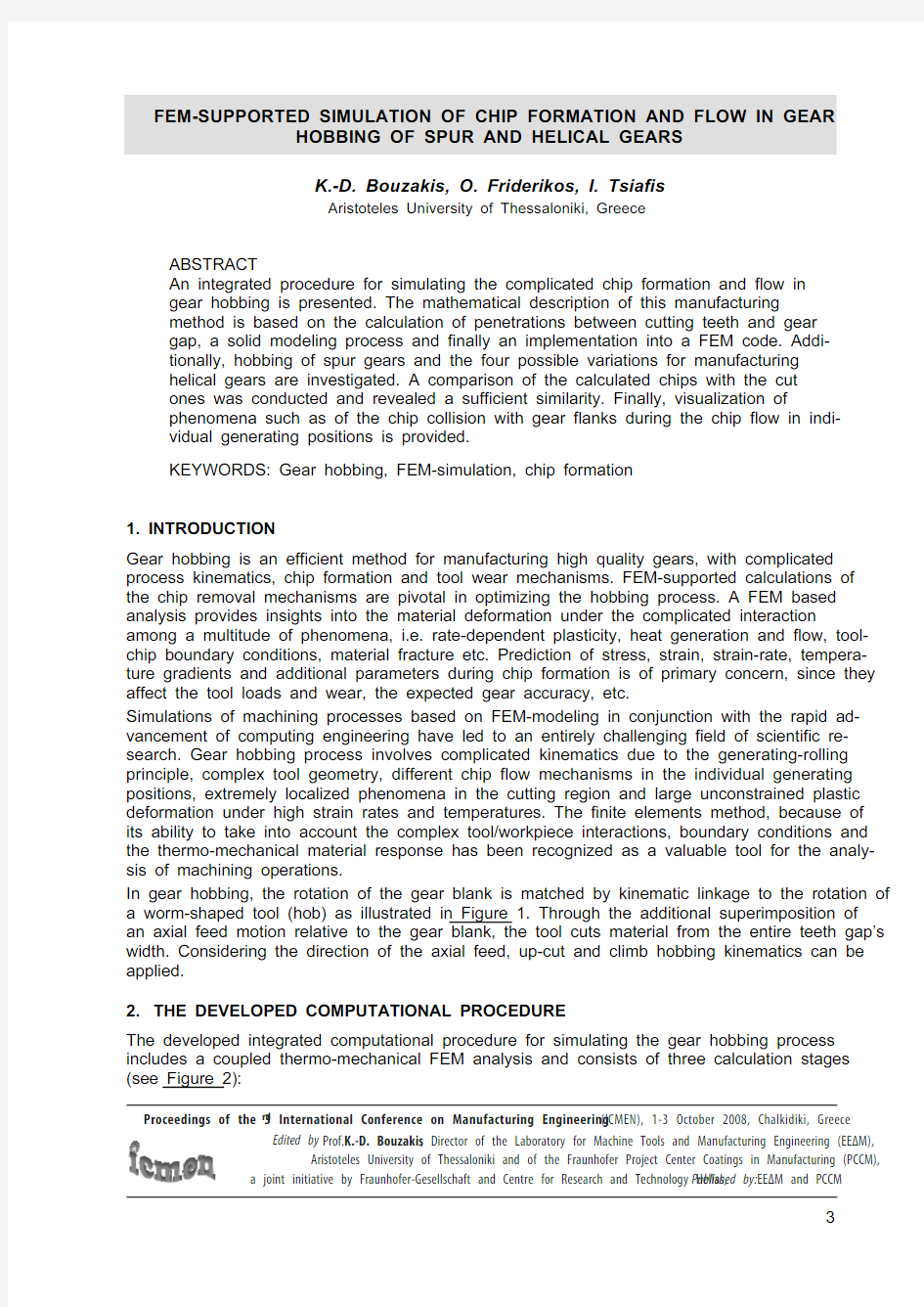
In gear hobbing, the rotation of the gear blank is matched by kinematic linkage to the rotation of a worm-shaped tool (hob) as illustrated in Figure 1. Through the additional superimposition of an axial feed motion relative to the gear blank, the tool cuts material from the entire teeth gap’s width. Considering the direction of the axial feed, up-cut and climb hobbing kinematics can be applied.
2. THE DEVELOPED COMPUTATIONAL PROCEDURE
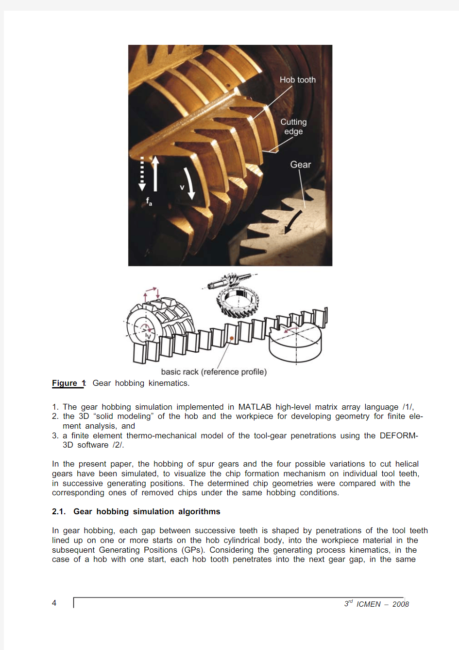
The developed integrated computational procedure for simulating the gear hobbing process includes a coupled thermo-mechanical FEM analysis and consists of three calculation stages (see Figure 2):
4 3rd
ICMEN – 2008
Figure 1: Gear hobbing kinematics.
1. The gear hobbing simulation implemented in MATLAB high-level matrix array language /1/,
2. the 3D “solid modeling” of the hob and the workpiece for developing geometry for finite ele-ment analysis, and
3. a finite element thermo-mechanical model of the tool-gear penetrations using the DEFORM-3D software /2/.
In the present paper, the hobbing of spur gears and the four possible variations to cut helical gears have been simulated, to visualize the chip formation mechanism on individual tool teeth, in successive generating positions. The determined chip geometries were compared with the corresponding ones of removed chips under the same hobbing conditions.
2.1. Gear hobbing simulation algorithms
In gear hobbing, each gap between successive teeth is shaped by penetrations of the tool teeth lined up on one or more starts on the hob cylindrical body, into the workpiece material in the subsequent Generating Positions (GPs). Considering the generating process kinematics, in the case of a hob with one start, each hob tooth penetrates into the next gear gap, in the same
Plenary
5
Figure 2: Procedures for the FEM-supported simulation of gear hobbing.
6 3rd ICMEN – 2008
generating position and removes a chip with the same geometry as in the previous gear gap. By the axial feed of the cutter, the tooth gaps are formed over the entire width of the wheel.
The gear hobbing simulation software FRS/MAT was developed in the matrix-oriented pro-gramming language MATLAB /1,3/. This computer supported analysis is based on the geomet-rical simulation of the cutting teeth penetrations into a gear gap, which is performed considering the hob geometry, the machining data and the kinematics of the actual process /4-6/. The gear hobbing kinematics analysis is accomplished by establishing coordinate systems to describe individual parts within the process kinematic chain, as exhibited in Figure 3a and 3b. Transformation matrices describe the relative position of the coordinate systems. Accordingly, the kinematic linkage representation of the gear blank and the tool is determined through se-quential transformations (matrix multiplications) /4,5/. Six coordinates systems are assigned for the gear hobbing kinematics:
System 1 is fixed in the gear gap. The origin is located at the pitch circle with the z 1 axis lying along the helix angle of the gear blank. The x 1
and y 1 axes are normal to the z 1 axis.
Figure 3: (a) Solid modelling of tool and work gear and (b) assembly into the gear hobbing
kinematic chain.
Plenary 7
System 2, rotating coordinate system fixed in gear blank. The origin is located at the center of the gear blank with the z 2 axis lying along the gear blank symmetry axis.
System 3, stationary machine’s reference system.
System 4, the origin is lying along y 3 axis: The distance between the hob spindle axis and the gear blank axis is assigned.
System 5, the origin is located along z 4 direction. The x 5-axis is lying along the hob axis inclina-tion angle (pivoting angle).
System 6, the origin of the system is translated along the x 5 axis in order to simulate any tooth of the worm shape tool. The y 6 axis coincides with the symmetry axis of the hob tooth profile.
Taking into account the rotation of the hob and the superimposition of the feed motion (axially, radially, etc.), the trace of the cutter is discretized into a number of static instances, namely into distinguished revolving positions, depending on the required computational accuracy. The trace of the cutting edge generates an enveloping surface of the tooth motion. The enveloping sur-face of the cutting edge is considered as the union of the points that belongs to the trace of the cutting edge of the cutting tooth, when it penetrates into a gear gap. The geometry of the gear gap is described by contours on perpendicular section planes to the gear axis. During the rela-tive movement of the hob, the intersection between the tooth’s enveloping surface and the gear reference cutting planes constitute the chip in an individual GP. Thereafter, a calculating proce-dure is utilized to compute the chip cross sections on the development of the cutting edge, and in this way to determine the distribution of the undeformed chip thickness. A linear interpolation is applied between the reference cutting planes to provide a continuous chip. In sequence, the gear gap geometry is updated for the next tooth penetration by subtracting the intersection area from the gear reference cutting planes. A characteristic result is displayed in Figure 4, calculated by the developed FRS/MAT software /3,7/. The undeformed chip thickness is presented over the
development of the cutting edge, on successive section levels in a single generating position by means of a colour scale. A similar graphical presentation of the undeformed chip geometry in the individual GPs is provided by the SPARTA-software /8,9/.
Figure 4: Characteristic undeformed chip geometry presentation in a single generating position
during gear hobbing calculated by FRS/MAT.
8 3rd ICMEN – 2008
2.2. Solid modeling
Solid modeling is used to develop the 3D geometry applied in the FEM simulation. In the solid modeling procedure two objects for the hob tool were created: a cylinder and a single tooth of the cutter rack (Figure 3a). Utilizing the parametric and associative nature of the solid modeler program (Solidworks) /10/, the single cutting tooth simulates any teeth of the worm shape tool through the translation and rotation of appropriate coordinate systems. The hob tooth profile corresponds to the DIN 3972 standards /11/ or to any other desired geometry. At a final stage, the solid models of the hob tooth and the cylinder are assembled together as presented in Fig-ure 3b. The prescribed coordinate systems were also used in the solid modeling procedure to provide the exact joining of the solid models at any stage of the manufacturing process.
The solid models of the instantaneous gear gap and the hob were created within the environ-ment of the applied solid modeling CAD program and then were stored using the STL neutral file format.
The gear blank consists of a single gear gap and a gear cylinder with radius equal to the exter-
nal radius of the gear. A point cloud in the 3D space describes the geometry of the gear gap on reference section levels perpendicular to the gear axis, as demonstrated in Figure 5, provided with the gear hobbing simulation software FRS/MAT. Following that, the data are inserted into a CAD system for processing and generating a triangular mesh.
Figure 5: Discretization of an instantaneous gear gap geometry and triangular mesh genera-
tion.
A large number of triangular elements (facets) are necessary to approximate the complex gear gap surface geometry. In the example displayed in Figure 5, approximately 20.000 facets were used. Considering the difficulties to insert shape information from the CAD into the FEM system, as STL triangulations cannot be used directly for FEM purposes, a new mesh has to be created /12/. Generation of the FE mesh from the original geometry is implemented using a mesh gen-eration system. The accuracy of the final object geometry that used in the FEM engine is based on the size of the tetrahedral elements. As the mesh density, i.e. the number of the tetrahedral elements, increases the new geometry closely approximates the geometry of the STL file.
2.3. FEM- based modeling of gear hobbing
The applied model using the DEFORM-3D software is based on an implicit Lagrangian incre-mental formulation, i.e. the finite element mesh is generated in the workpiece and follows its deformation. An unstructured tetrahedral finite element mesh is generated in the workpiece using the Automatic Mesh Generation system (AMG). On the one hand, Lagrangian methods are well suited to simulate transient and discontinuous machining processes; on the other hand, a number of disadvantages are associated with Lagrangian methods. They are computationally expensive, as relative small time steps are required in transient solutions. Moreover, in applying Lagrangian formulations to problems of large plastic deformations, such as machining, the mesh can be distorted severely.
One way to overcome the large plastic deformation is to simulate machining by remeshing the workpiece to offset mesh distortions due to deformation caused by the tool feed. This occurs when a negative Jacobean is encountered (severely distorted elements) or on assignment of certain triggers (remeshing criteria). DEFORM 3D uses the AMG to automatically provide an optimised remeshing process. However, computational errors that occur due to interpolation of the nodal state variables between meshes are a drawback of the remeshing process.
Another important tool incorporated in the used FEM code is the mesh adaption, capable of predicting non-steady chip formation. Weighting factors that specify the relative mesh density to regions of high curvature or of steep strain, strain rate and temperature gradients can be as-signed individually. Areas can also be specified geometrically to generate a fine or coarse mesh using mesh density windows. Thus, the adaptive meshing system generates the minimum size elements in chip zone and substantially larger elements away from the chip and cutting zone.
An improved understanding of the implications of minimum length scales encountered in ma-chining is needed for the convergence and efficiency of numerical computations. I n order to adequately address this in the solution, a high degree of mesh refinement is required /13/. The features that require a fine mesh in machining are the mechanical and thermal boundary layers that develop in the contact region and within localized shear bands.
The workpiece was modeled as rigid-viscoplastic, (the flow stress is a function of strain, strain rate and temperature), homogenous, with isotropic yield function (von Mises) and isotropic strain hardening rule.
The cutting tool was modeled as rigid. Based on this assumption there is no need to assign its mechanical properties and thus, only thermal properties were defined. Moreover, compared with the large plastic deformation of the gear material, the tool elastic deflection can be neglected without loss of accuracy. An unstructured tetrahedral mesh is also used on the cutting tooth for thermal calculations. No remeshing is necessary on the tooth.
Plenary 9
10 3rd ICMEN – 2008
3. MATERIAL FLOW STRESS LAWS AND BOUNDARY CONDITIONS USED IN THE
FEM-CALCULATIONS
One of the critical issues of a FEM simulation is the reliability and accuracy of the flow stress model to represent the material behaviour in metal cutting, since extremely localized phenom-ena are encountered in the cutting process, characterized by large non-linear unconstrained plastic flow and high deformation rates.
In the constitutive model proposed by S. Lei /14/, material flow stress data of C22 (AISI 1020) were obtained through orthogonal machining experiments. Despite the limitations and restric-tions of the plane strain model, it is utilized to describe the non-steady, multi-dimensional stress states, as the occurring ones, when simulating gear hobbing. The flow stress is determined by the product of strain, strain rate and temperature effects that are individually determined, as described by the equation:
)(000H m n T F ???
?????????????=εεσσ (1)
In (1) there exist no couplings among strain, strain rate and temperature and also no effect on the strain history. The reference value of the stress is σο, while the strain and strain rate are normalized with the values εο and o ε respectively; n and m are material parameters indicating
strain hardening and strain rate hardening coefficients respectively; T H is the homologous tem-perature, i.e. the ratio of the material temperature T , to material melting point temperature T m , which is assumed to be 1848 K for the applied AISI 1020 steel. F (T H ) considers the effect of temperature on the stress and is defined in two regions:
21)(C T C T F H H +=,
0.472H T ≤ and (2)
()()652433)()(C T C T C T C T F H H H H +++=,
0.4720.635H T ≤≤ (3)
Equation (3) takes into account the influence of the blue brittleness effect on the flow stress, which is inherent in low carbon steels and is considered to be a result of dynamic strain ageing. The coefficients of the flow stress equation are listed in Table 1. The applicable bounds of this constitutive equation are:
? strain range: 0 up to 2 ? strain rate range: up to 50.000 s -1
? temperature range: 25 up to 650 o C. If the process conditions are in an area outside of the flow stress region, i.e. for strains larger than 2, constant values of the flow stress have been assumed in order to prevent extrapola-tions.
Table 1: Flow stress equation coefficients. σο [MPa] εο 0ε n m C 1
780 0.85 16.000 0.34 0.08 -1.52
C 2 C 3
C 4 C 5 C 6 1.49 135.2 -268.7 169.6 -33.5
Furthermore, the work material properties were first used in the orthogonal machining theory described by Oxley and Hastings /15,16/ implemented into the FEΜ code. According to Oxley
Plenary 11
/17/, results of high-speed compression tests of plain carbon steels (0.16-0.55%) obtained by Oyane /18/, is possible to extrapolate into the machining range by using the velocity-modified temperature concept suggested by MacGregor and Fisher /19/. A linear log stress/log strain relation represents the flow stress properties of the work material:
()()mod 1mod n T T σσε= ,
(4)
where σ and ε are the uniaxial flow stress and strain; the strength coefficient σ1 and the strain hardening exponent n are functions of the velocity-modified temperature T mod . The velocity-modified temperature describes the material properties as a relation between the temperature and strain rate. This can be expressed as:
?????????????=o v T T ε
ε log 1mod (K) , (5)
where T is the temperature, ε
is the strain rate and v and o ε are constants. Equation (5) dem-onstrates the expected qualitative result that an increase in strain-rate is equivalent to a de-crease in temperature. However, at temperatures less that the recrystallization temperature, equation (5) can only be regarded as approximate /20/. Oxley’s equation for AI SI 1020 steel was included in tabular format in the material database of DEFORM-3D. The related applicable limits are:
? strain range: up to 5 ? strain rate range: up to 20.000 s -1
? temperature range: 20 up to 1.300 o C .
The tool/chip boundary conditions are quite complex, influenced by a number of factors such as cutting speed, feed rate, etc. /21/. While several models were presented to determine the friction boundary conditions, an accurate description is still unavailable and the correlation with experi-mental data is poor. Researchers present conflicting viewpoints concerning the nature of the tool-chip frictional conditions to the point where definitive conclusions cannot be drawn /22/. In the present paper, a shear friction law was assumed by considering only high normal stresses on the sticking region, defined by the relationship:
τf = m k chip , (6) where m (0 k chip =3/σ, (7) with σ being the effective yield stress under pure uniaxial tension. The constant shear friction factor m was varied in the range of 0.60-0.95 to investigate the sensitivity on the simulated chip flow and chip geometry. Additional work has been carried out to explore the friction boundary conditions and to provide a reliable model for the gear hobbing process /3/. 4. CHIP FORMATION IN GEAR HOBBING OF SPUR GEARS DETERMINED BY FEM-BASED CALCULATIONS AND SELECTION OF APPROPRIATE MATERIAL FLOW STRESS LAW The undeformed chip cross-sections, on the development of the cutting edge, in successive tool revolving positions are presented in five characteristic GPs in Figure 6. I n this manufacturing case, the material removal from a tooth gap takes place in 26 individual GPs. This case was considered as a test one to demonstrate the possibilities of the developed FEM hobbing simula- 12 3rd ICMEN – 2008 tion and to select the most appropriate material flow stress law. The data of GP -9 are input into the developed FEM procedure to enable the visualization of the complicated chip formation mechanism and to provide information of the occurring stresses, temperatures, strains, strain rates, etc. The performed FEM-calculations are associated to up-cut gear hobbing, while cutting experiments were conducted in conjunction, for the model validation. The associated chip flow is visualized in four successive tool rotational positions (steps), as shown in Figure 7. At section (I) the chip is generated when the leading and the trailing flank starts to penetrate into the gear material, at low chip thicknesses. Following that, a three-flank chip is formed, since the tooth head starts to cut, as shown in section (II). The material removal between sections (II) and (III) is dominated by intense chip flow obstruction due to the reciprocal collision of chip distinct seg-ments. The complicated chip flow obstruction at this region exhibits a remarkable influence on the tool wear progress, specifically at the transient cutting edge regions from the cutting tooth head to the flanks, as reported in extended investigations /6,23,24/. Finally, the chip removal is completed and the tool exits from the workpiece gap (see section (IV)). Figure 6: Chip formation in characteristic generating positions during up-cut gear hobbing, calculated by FRS/MAT. Plenary 13 Figure 7: Chip formation in an individual generating position during gear hobbing. Two opposite views of the real chip, the upper side view and a rake side view corresponding to the simulated GP –9, are provided in Figure 8. Moreover, the same views of the FEM-calculated chip according to Lei’s and Oxley’s flow stress laws are also illustrated in this figure. As it can been seen in the table inserted at the bottom of the figure, the mean undeformed chip thickness of the tooth head region is approximately h ≈0.25 mm calculated by FRS/MAT, with a mean undeformed length of l ≈16 mm. Considering the real chip dimensions, the mean chip thickness in the tooth head region amounts to h ch ≈0.6 mm with a mean length of l ch ≈6.7 mm. On the one hand, an overestimation of the chip plastic deformation in the FEM-based calculations is evi-dent, considering the real and the simulated chip, when using the Lei’s flow stress law. On the other hand, using as input data the material flow stress after Oxley, the plastic deformation of the real chip is underestimated but the calculated chip geometry is closer to the real one, as the corresponding chip dimensions in Figure 8. Therefore, the Oxley material flow stress law /17/ was applied in the performed FEM-calculations presented in the following sections. 14 3rd ICMEN – 2008 Figure 8: Real chip geometry and FEM-calculated ones considering various material flow stress laws. 5. CHIP FORMATION DETERMINED BY FEM BASED CALCULATIONS IN GEAR HOBBING OF HELICAL GEARS For manufacturing helical gears by hobbing, there are two variations depending on the helix angle directions of the cutting tool and the gear blank cylinder. Equi-directional hobbing is set when the helix angle directions of the hob (γ) and the gear blank (β2) are the same, while in the opposite case, counter-directional hobbing is applied. Hence, a different pivoting angle (n= β2 ± γ) results in these machining cases. In this way, four possible cutting variations i.e. the up-cut equi-directional and counter-directional, as well as the climb equi-directional and counter-directional gear hobbing occur, as illustrated in Figure 9. FEM simulations of the four possible cutting variations for the cutting of helical gears were per-formed to investigate the chip formation mechanism in characteristic GPs, where ‘’three flank’’ chips are removed. The chip formation affects the stresses and temperatures that limit the tool life of the cutting tooth and the surface integrity of the work gear flank. A number of phenomena can be predicted using the finite element analysis, i.e. chip flow obstruction during chip genera-tion and potential chip collision with the gear flanks, as well. The later can result into pinching and crushing of the generated chip between the cutting edge of the hob and the tooth flank of the work gear /25/. For the above-mentioned reasons, the most critical GPs concerning chip formation and flow were selected for FEM simulation. In order to validate the FEM model com-parative experiments were carried out in gear hobbing. The obtained results are presented in the following sections. Plenary 15 Figure 9: The four possible cutting variations in hobbing of helical gears. 5.1. Up-cut counter-directional kinematics In this manufacturing case a total number of 36 GPs are required to generate the involute gear tooth profile. The development of the cutting edge is divided into three regions corresponding to the tooth head (H-H), the Leading and the Trailing Flank (LF, TF) respectively. Simulation data provided by the developed software FRS/MAT for GP -16, which is considered one of the most critical positions concerning the tool wear development /6,23,24/, were input into the FEM sys-tem to investigate the complicated chip formation mechanism and to get information about the occurring stresses, temperatures, strains, strain rates, etc. In Figure 10 the chip formation proceeds in the order (I), (II), (III) and (IV) according to the proc-ess kinematics. The corresponding revolving positions are superimposed on the undeformed chip geometry as shown at the bottom part of the figure. As the cutting tooth engages the work gear, the LF and then the TF penetrate into the gear material. Next, the tooth head starts to cut and a ‘three-flank’ chip is formed. As cutting proceeds further, the chip segments on the LF and TF are moving towards the chip segment generated on the cutting head and finally collide (be-yond section (II)). Finally the material removal is completed and the tool exits from the gear gap (see section (IV)). 5.2. Climb counter-directional kinematics I n the investigated climb counter-directional kinematics gear hobbing test case, 31 GPs are required to create the gear gap geometry. The data of GP 7 provided by the FRS/MAT software were input into the developed FEM system to simulate the chip formation mechanism. The chip formation in four characteristic stages of the simulation, (I), (II), (III), (IV) is shown in Figure 11. 16 3 rd ICMEN – 2008 Figure 10: Chip formation in a generating position during up-cut counter-directional gear hob- bing. The same revolving positions are superimposed on the undeformed chip geometry as shown at the bottom part of the figure. In contrast to up-cut kinematics, the tooth head is penetrating first into the work gear and an entirely different plastic deformation of the work gear material results due to the opposite axial feed direction. The cutting proceeds in the following sequence: first, the tooth head penetrate into the gear gap where the maximum undeformed chip thickness of h max ≈0.42 mm occurs. As the hob tooth moves towards section (II), the LF first and then the TF starts to cut. The chip is moving towards the tooth root of the hob and curls during the last stages of the chip formation (see section (IV)). Next, the penetration of the tooth head into the work gear is completed and at the final revolving positions the material is removed only by the LF and the TF. Beyond section (IV) the TF acts alone until the end of cutting. An interesting result of the FEM simulation is the chip collision with the machined work gear flank at the final stages of chip formation. Using the developed FEM- model important process data such as the temperature, stress and strain fields developed in the Plenary 17 Figure 11: Chip formation in GP 7 during climb counter-directional gear hobbing at various rota-tional steps. chip can be continuously monitored during the chip formation and flow, as exhibited in Figure 12. Although the chip formation and flow are well described by the developed FEM-supported pro-cedure, the results accuracy concerning temperature, stresses and strains are affected by the descretization grade of the gear and hob solid geometry /26/. Thus, more efficient and less time-consuming FEM-algorithms have to be developed. 5.3. Comparison between real and FEM-calculated chip geometries Various investigations have been conducted to check the validity of the developed FEM-based method, to compare among others the real chip geometries with the FEM-determined ones, considering known material constitutive laws as described in a previous section. Characteristic comparisons can be seen in Figure 13. These chips were removed in gear hobbing with differ-ent cutting kinematics (climb, or up-cut hobbing) and tool helix directions related to the work 18 3rd ICMEN – 2008 gear flank inclination (equi, or counter directional). A comparison of few characteristic chip di- mensions reveals that the developed FEM model describes sufficiently the real chip geometry. Hence, it is possible to optimise the tool design in order to facilitate the chip flow, to decrease cutting loads in endangered cutting edge regions, to predict collisions of the chips with the in-stantaneous gear flanks in the various GPs etc. Figure 12: Continuous FEM-supported determination of temperature, stress and strain fields in a generating position during gear hobbing. Figure 13: Comparison between real and FEM-calculated chip geometries. 6. CONCLUSIONS A FEM-supported methodology was introduced to simulate the chip formation and flow in gear hobbing. The developed FEM model capabilities have been demonstrated in terms of chip flow and morphology in cutting of spur gears as well as in the four possible cutting variations of heli-cal gears. An insight of the complex chip formation mechanism is provided, enabling the clarifi-cation of phenomena like the chip flow obstruction and the chip collision with gear flanks in indi-vidual generating positions during the manufacturing of a gap. Moreover, the FEM calculations provide an effective tool for predicting occurring temperatures, strain and stresses and thus for approaching the real loads of the cutting teeth during gear hobbing. 7. REFERENCES 1. MATLAB, version 7.3.0.267, (R2006b). 2. DEFORM 3D, version 6.1 (Beta 3), Scientific Forming Technologies Corporation. 3. Friderikos O., 2008, Ph.D. Thesis, Simulation of chip formation and flow in gear hobbing using the finite element method, Aristoteles Universtity of Thessaloniki, Greece. 4. Sulzer, G., 1973, Leistungssteigerung bei der Zylinderradherstellung durch systematische Erfassung der Zerspantechnik, Dissertation, RWTH-Aachen, Germany. 5. Sulzer, G., 1974, Bestimmung der Spanungs-querschnitte beim Waelzfraesen, Industrie- Anzeiger 12:246-247. 6. Bouzakis K.-D., Kombogiannis S., Antoniadis, A., Vidakis N., 2002, Gear Hobbing Cutting Process Simulation And Tool Wear Prediction Models, Journal of Manufacturing Science and Engineering, ASME, 124:42-51. 7. Bouzakis, K.-D., Friderikos, O., Mirisidis, I., Tsiafis, I., 2005, Determination of Chip Ge- ometry and Cutting Forces in Gear Hobbing by a FEM-based Simulation of the Cutting Process, Proceedings of the 8th CI RP I nternational Workshop on Modeling of Machining Operations, Chemnitz, Germany:49-58. 8. Eversheim, W., Pfeifer, T., Weck, M., 2006, 100 Jahre Produktionstechnik, Springer- Verlag, Berlin Heidelberg, Germany. 9. Weck, M., 2002, Analysieren erspart das probieren, Das Industrie Magazin: 76-78. 10. Solidworks, 2006, User’s Guide Manual, Solidworks Corporation, 2006. 11. DI N 3972, 1981, Bezugsprofile von Verzahnwerkzeugen fuer Evolventenverzahnungen nach DIN 867. 12. Bechét E., Cuilliere J.C, Trochu F., 2002, Generation of a finite element mesh from stereo- litography (STL) files, Computer-Aided Design, 34/1:1-17. 13. Marusich T. D., Ortiz M., 1995, Modeling and simulation of high-speed machining, Int. J. Num. Meth. Eng., 38 /21:3675–3694. 14. Lei, S., Shin, Y.C., Incropera, F.P., 1999, Material Constitutive Modeling Under High Strain Rates and Temperatures Through Orthogonal Machining Tests, Journal of Manufacturing Science and Engineering, 121:577-585. 15. Oxley, P.L.B and Hastings, W.F., 1976, Phil. Trans. R. Soc., A282:656-584. 16. Oxley, P.L.B and Hastings, W.F., 1977, Proc. R. Soc., A356:395-410. 17. Oxley, P. L. B., 1989, The Mechanics of Machining: An Analytical Approach to Assessing Machinability, E. Horwood, Chichester, England. 18. Oyane, M., Takashima, F., Osakada, K., Tanaka, H.,1967, The Behaviour of Some Steels Under Dynamic Compression, 10th Japan Congress on Testing Materials: 72-76. 19. MacGregor, C.W., Fisher, J.C., 1946, A Velocity-Modified Temperature for the Plastic Flow of Metals, ASME J. Appl. Mech., 13:11-16. 20. Slater R.A.C., 1977, Engineering Plasticity: Theory and Application to Metal Forming Processes, Macmillan, London and Basingstoke: 151. Plenary 19 21. Childs T.H., Dirikolu M.H., Sammons M.D.S., Maekawa K., Kitagawa T., 1997, Experi- ments on and finite element modeling of turning free-cutting steels at cutting speeds up to 250 m/min, Proceedings of 1st French and German Conference on High-speed Machin-ing:325–331. 22. Wright P.K., Horne J.G., Tabor D.,1979, Wear, Boundary conditions at the chip-tool inter- face in machining: Comparisons between seizure and sliding friction, 54:371-390. 23. Bouzakis, K.-D., Koenig, W., 1981, Process Models for the Incorporation of Gear Hobbing into an Information Centre for Machining Data, Annals of the CIRP, 30/1:77-82. 24. Bouzakis, K.-D., 1980, Konzept und technologishe Grundlagen zur automatisierten Erstel- lung optimaler Bearbeitungsdaten beim Waelzfraesen, Habilitation, TH Aachen. 25. Komori M., Sumi M., Kubo A., 2004, Method of Preventing Cutting Edge Failure of Hob Due to Chip Crush, JSME International Journal, Series C, 47/4. 26. Fischer C., Runtime and Accuracy Issues in Three Dimensional Finite Element Simulation of Machining, 2007, Proceedings of the 10th CIRP International Workshop on Modeling of Machining Operations: 45. 20 3rd ICMEN – 2008 高考文科数学模拟试卷 一、选择题:本大题共10小题,每小题5分,共50分.在每小题给出的四个选项中,只有一项是符合题目要求的. 1.已知复数z满足(2﹣i)2?z=1,则z的虚部为() A.B.C.D. 2.已知集合A={x|x2=a},B={﹣1,0,1},则a=1是A?B的() A.充分不必要条件B.必要不充分条 C.充要条件D.既不充分也不必要条件 3.设单位向量的夹角为120°,,则|=() A.3 B. C.7 D. 4.已知等差数列{a n}满足a6+a10=20,则下列选项错误的是() A.S15=150 B.a8=10 C.a16=20 D.a4+a12=20 5.一几何体的三视图如图所示,则该几何体的体积为() A.B.C.4﹣πD. 6.双曲线=1的顶点到其渐近线的距离为() A. B.C. D. 7.周期为4的奇函数f(x)在[0,2]上的解析式为f(x)=,则 f(2014)+f(2015)=() A.0 B.1 C.2 D.3 8.已知x,y满足约束条件,则z=2x+y的最大值为() A.2 B. C.4 D. 9.在△ABC中,内角A、B、C的对边分别是a、b、c,若c2=(a﹣b)2+6,△ABC的面积为,则C=() A.B.C.D. 10.设f′(x)为函数f(x)的导函数,已知x2f′(x)+xf(x)=lnx,f(1)=,则 下列结论正确的是() A.xf(x)在(0,+∞)单调递增B.xf(x)在(1,+∞)单调递减 C.xf(x)在(0,+∞)上有极大值 D.xf(x)在(0,+∞)上有极小值 二、填空题:本大题共5小题,每小题5分,共25分. 11.右面的程序框图输出的S的值为. 12.在区间[﹣2,4]上随机取一个点x,若x满足x2≤m的概率为,则m= .13.若点(a,9)在函数的图象上,则a= . 14.已知x>0,y>0且2x+y=2,则的最小值为. 第 1 页 共 10 页 图 1 图2 圆梦2015·高三数学(理)仿真模拟三 一、选择题:本大题共8小题,每小题5分,满分40分.在每小题给出的四个选项中,只有一项是符合题目要求的. 1.已知函数lg y x =的定义域为A ,{} 01B x x =≤≤,则A B =( ) A .()0,+∞ B .[]0,1 C .(]0,1 D .[)0,1 2.设i 为虚数单位,若复数() ()2231i z m m m =+-+-是纯虚数,则实数m =( ) A .3- B .3-或1 C .3或1- D .1 3 .设函数sin 2y x x =的最小正周期为T ,最大值为A ,则( ) A .T π= ,A = B . T π=,2A = C .2T π= ,A = D .2T π=,2A = 4.某由圆柱切割获得的几何体的三视图如图1所示,其中俯视图是 中心角为60?的扇形,则该几何体的体积为( ) A . 3 π B .23π C .π D .2π 5.给定命题p :若20x ≥,则0x ≥; 命题q ::已知非零向量,,a b 则 “⊥a b ”是“-+=a b a b ”的充要条件. 则下列各命题中,假命题的是( ) A .p q ∨ B . ()p q ?∨ C .()p q ?∧ D .()()p q ?∧? 6.已知函数()222,02,0 x x x f x x x x ?+≥=?-)的比值a b ,称这些比值中的最小值为这个 数表的“特征值”.当2n =时, 数表的所有可能的“特征值”最 大值为( ) A .3 B . 43 C .2 D .32 第九章 数字电路基础知识 一、 填空题 1、 模拟信号是在时间上和数值上都是 变化 的信号。 2、 脉冲信号则是指极短时间内的 电信号。 3、 广义地凡是 规律变化的,带有突变特点的电信号均称脉冲。 4、 数字信号是指在时间和数值上都是 的信号,是脉冲信号的一种。 5、 常见的脉冲波形有,矩形波、 、三角波、 、阶梯波。 6、 一个脉冲的参数主要有 Vm 、tr 、 Tf 、T P 、T 等。 7、 数字电路研究的对象是电路的输出与输入之间的逻辑关系。 8、 电容器两端的电压不能突变,即外加电压突变瞬间,电容器相当于 。 9、 电容充放电结束时,流过电容的电流为0,电容相当于 。 10、 通常规定,RC 充放电,当t = 时,即认为充放电过程结束。 11、 RC 充放电过程的快慢取决于电路本身的 ,与其它因素无关。 12、 RC 充放电过程中,电压,电流均按 规律变化。 13、 理想二极管正向导通时,其端电压为0,相当于开关的 。 14、 在脉冲与数字电路中,三极管主要工作在 和 。 15、 三极管输出响应输入的变化需要一定的时间,时间越短,开关特性 。 16、 选择题 2 若一个逻辑函数由三个变量组成,则最小项共有( )个。 A 、3 B 、4 C 、8 4 下列各式中哪个是三变量A 、B 、C 的最小项( ) A 、A B C ++ B 、A BC + C 、ABC 5、模拟电路与脉冲电路的不同在于( )。 A 、模拟电路的晶体管多工作在开关状态,脉冲电路的晶体管多工作在放大状态。 B 、模拟电路的晶体管多工作在放大状态,脉冲电路的晶体管多工作在开关状态。 C 、模拟电路的晶体管多工作在截止状态,脉冲电路的晶体管多工作在饱和状态。 D 、模拟电路的晶体管多工作在饱和状态,脉冲电路的晶体管多工作在截止状态。 6、己知一实际矩形脉冲,则其脉冲上升时间( )。 A 、.从0到Vm 所需时间 B 、从0到2 2Vm 所需时间 C 、从0.1Vm 到0.9Vm 所需时间 D 、从0.1Vm 到 22Vm 所需时间 7、硅二极管钳位电压为( ) A 、0.5V B 、0.2V C 、0.7V D 、0.3V 8、二极管限幅电路的限幅电压取决于( )。 A 、二极管的接法 B 、输入的直流电源的电压 C 、负载电阻的大小 D 、上述三项 9、在二极管限幅电路中,决定是上限幅还是下限幅的是( ) A 、二极管的正、反接法 B 、输入的直流电源极性 C 、负载电阻的大小 D 、上述三项 10、下列逻辑代数定律中,和普通代数相似是( ) A 、否定律 B 、反定律 C 、重迭律 D 、分配律 绝密★启 用前2020 年普通高等学校招生全国统一考试 理科综合能力测试试题卷 ( 银川一中第一次模拟考试) 注意事项: 1.答卷前,考生务必将自己的姓名、准考证号填写在答题卡上。 2.作答时,务必将答案写在答题卡上。写在本试卷及草稿纸上无效。 3.考试结束后,将本试卷和答题卡一并交回。 可能用到的相对原子质量:H-1 C-12 N-14 O-16 P-31 S-32 Cl-35.5 Ca-40 V-51 Fe-56 Cu-64 Zn-65 一、选择题:本题共13 小题,每小题6 分,在每小题给出的四个选项中,只有一项是符合题目要求的。 1.下列关于生物大分子的叙述中,正确的是 A.肺炎双球菌、烟草花叶病毒都含有核糖体和核 酸B.生物体内参与信息传递的信息分子都是蛋白 质 C.细胞质中的核酸只含核糖,细胞核中的核酸只含脱氧核糖 D.人的吞噬细胞和浆细胞结构和功能不同,根本原因是遗传信息执行情况不同 2.某农作物细胞间隙的浓度为a,细胞液的浓度为b,细胞质基质的浓度为c,在对农 作物施肥过多造成“烧苗”过程中,三者之间的关系是 A.a>b>c B.b>c>a C.a>c>b D.b>a>c 3.下列关于变异和进化的说法,正确的是 A.用秋水仙素处理单倍体植株后得到的一定是纯合子 B.在三倍体无子西瓜的培育过程中,用四倍体西瓜作母本,用二倍体西瓜作父本,得到 的种子胚细胞中含有三个染色体组 C.两个种群间的隔离一旦形成,这两个不同种群的个体之间就不能进行交配,或者即使 能交配,也不能产生可育后代 D.突变能为生物进化提供原材料,但不包括染色体数目的变异,因为该过程并没有新的 基因产生 高考文科数学模拟题 一、选择题: 1.已知集合{}{} 12,03A x x B x x =-<=<<,则A B =() A .{} 13x x -<”是“0< 高考数学模拟试题 (第一卷) 一、选择题:(每小题5分,满分60分) 1、已知集合A={x|x 2+2ax+1=0}的真子集只有一个,则a 值的集合是 A .(﹣1,1); B .(﹣∞,﹣1)∪[1,+∞]; C .{﹣1,1}; D .{0} 2、若函数y=f(x)的反函数y=f -1(x)满足f -1(3)=0,则函数y=f(x+1)的图象必过点: A .(0,3); B .(-1,3); C .(3,-1); D .(1,3) 3、已知复数z 1,z 2分别满足| z 1+i|=2,|z 2-3-3i|=3则| z 1-z 2|的最大值为: A .5; B .10; C .5+13; D .13 4、数列 ,4 3211,3211,211++++++ ……的前n 项和为: A .12+n n ; B .1+n n ; C .222++n n ; D .2+n n ; 5、极坐标方程ρsin θ=sin2θ表示的曲线是: A .圆; B .直线; C .两线直线 D .一条直线和一个圆。 6、已知一个复数的立方恰好等于它的共轭复数,则这样的复数共有: A .3个; B .4个; C .5个; D .6个。 7、如图,在正方体ABCD —A 1B 1C 1D 1中,E 、F 是异面直 线AC ,A 1D 的公垂线,则EF 和ED 1的关系是: A . 异面; B .平行; C .垂直; D .相交。 8、设(2-X)5=a 0+a 1x+a 2x+…+a 5x 5, 则a 1+a 3+a 5的值为: A .-120; B .-121; C .-122; D .-243。 9、要从一块斜边长为定值a 的直角三角形纸片剪出一块圆形纸片,圆形纸片的最大面积为: A .2 πa 2; B .24223a π-; C .2πa 2; D .2)223(a π- 10、过点(1,4)的直线在x,y 轴上的截距分别为a 和b(a,b ∈R +),则a+b 的最小值是: A .9; B .8; C .7; D .6; 11、三人互相传球,由甲开始发球并作为第一次传球。经过5次传球后,球仍回到甲手中,则不同的传球方式共有: A .6种; B .8种; C .10种; D .16种。 12、定义在R 上的偶函数f(x)满足f(x+2)=f(x -2),若f(x)在[﹣2,0]上递增,则 A .f(1)>f(5.5) ; B .f(1) 模拟电子技术复习资料总结 第一章半导体二极管 一.半导体的基础知识 1.半导体---导电能力介于导体和绝缘体之间的物质(如硅Si、锗Ge)。 2.特性---光敏、热敏和掺杂特性。 3.本征半导体----纯净的具有单晶体结构的半导体。 4.两种载流子----带有正、负电荷的可移动的空穴和电子统称为载流子。 5.杂质半导体----在本征半导体中掺入微量杂质形成的半导体。体现的是半导体的掺杂特性。*P型半导体:在本征半导体中掺入微量的三价元素(多子是空穴,少子是电子)。 *N型半导体: 在本征半导体中掺入微量的五价元素(多子是电子,少子是空穴)。 6.杂质半导体的特性 *载流子的浓度---多子浓度决定于杂质浓度,少子浓度与温度有关。 *体电阻---通常把杂质半导体自身的电阻称为体电阻。 *转型---通过改变掺杂浓度,一种杂质半导体可以改型为另外一种杂质半导体。 7. PN结 * PN结的接触电位差---硅材料约为0.6~0.8V,锗材料约为0.2~0.3V。 * PN结的单向导电性---正偏导通,反偏截止。 8. PN结的伏安特性 二. 半导体二极管 *单向导电性------正向导通,反向截止。 *二极管伏安特性----同PN结。 *正向导通压降------硅管0.6~0.7V,锗管0.2~0.3V。 *死区电压------硅管0.5V,锗管0.1V。 3.分析方法------将二极管断开,分析二极管两端电位的高低: 若V阳>V阴( 正偏),二极管导通(短路); 若V阳 2) 等效电路法 直流等效电路法 *总的解题手段----将二极管断开,分析二极管两端电位的高低: 若V阳>V阴( 正偏),二极管导通(短路); 若V阳 银川一中2019届高三年级第一次月考 理科综合试卷 命题人:本试卷分第I卷(选择题)和第II卷(非选择题)两部分。其中第II卷第33?38题为选考题, 其它题为必考题。考生作答时,将答案写在答题卡上,在本试卷上答题无效。 第I卷(共126分) 可能用到的相对原子质量(原子量):H—1 0—16 Na—23 K—39 Mn—55 Cu—64 Ni—59 一、选择题:本题包括13小题。每小题6分,共78分,每小题只有一个选项符合题意。 1.下列有关病毒、原核生物和真核生物的描述,正确的是 A.病毒、原核生物和真核生物的共同点是遗传物质都是DM B.原核牛物和真核生物都具有完整的生物膜系统 C.病毒进入原核细胞后,细胞内的溶酶体会将其“消化” D.病毒能够借助原核生物或真核生物的核糖体来合成自身的蛋白质 2.玉米种子的萌发是种子的胚从相对静止状态变为生理活跃状态,并长成营自养生活的幼苗的过 程。下列关于该过程的叙述,正确的是 A.在萌发过程中,主要以被动运输的方式从外界吸收水和无机盐 B.在萌发过程中,细胞呼吸加强,导致细胞内有机物的总量一直减少 C.萌发过程中,各细胞的形态、结构和功能发生稳定性差异,但遗传物质没有发生变化 D.种子萌发初期增加的主要元素为C元素 3.结构与功能相统一是生物学的基本观点之一。下列叙述不能说明这一观点的是 A.叶绿体内类囊体膜堆叠使膜面积增大,利于光能充分利用 B.神经细胞轴突末梢有大量突起,有利于附着更多的神经递质受体蛋白 C.细胞骨架能维持真核细胞的形态,它与细胞的物质运输等活动有关 D.线粒体内膜向内突起形成悄,有利于附着更多的有氧呼吸有关的酶 4.自噬作用是普遍存在于大部分真核细胞屮的一种现象,是溶酶体对自身结构的吞噬降解,它是 细胞内的再循环系统。下列哪一项不属于自噬作用 A.为细胞内新细胞器的构建提供原料,即细胞结构的再循环 B.吞噬细胞吞噬受病每感染的细胞 C.衰老的细胞进入编程死亡过程屮的细胞内的吞噬 D.清除降解细胞内受损伤的细胞结构、衰老的细胞器 5.与物质跨膜运输相关的叙述正确的是 2020年高考文科数学模拟试卷及答案(共三套) 2020年高考文科数学模拟试卷及答案(一) 一、选择题:(本大题共12小题,每小题5分,在每小题给出的四个选项中,只有一项符合题目的要求) 1、设集合{}1 2 3 4U =,,,,集合{}2540A x x x =∈-+ 2018高考文科数学模拟试题 一、选择题: 1.已知命题,,则是成立的( )条件. A .充分不必要 B .必要不充分 C .既不充分有不必要 D .充要 2.已知复数,,,是虚数单位,若是实数,则( ) A . B . C . D . 3.下列函数中既是偶函数又在上单调递增的函数是( ) A . B . C . D . 4.已知变量,之间满足线性相关关系 ,且,之间的相关数据如下表所示:则( ) A .0.8 B .1.8 C .0.6 D .1.6 5.若变量,满足约束条件,则的最大值是( ) A .0 B .2 C .5 D .6 6.已知等差数列的公差和首项都不为,且成等比数列,则( ) A . B . C . D . 7.我国古代数学名著《孙子算经》中有如下问题:“今有三女,长女五日一归,中女四日一归,少女三日一归.问:三女何日相会?”意思是:“一家出嫁的三个女儿中,大女儿每五天回一次娘家,二女儿每四天回一次娘家,小女儿每三天回一次娘家.三个女儿从娘家同一天走后,至少再隔多少天三人再次相会?”假如回娘家当天均回夫家,若当地风俗正月初二都要回娘家,则从正月初三算起的 :12p x -<<2:log 1q x 2019年高考数学仿真模拟试题 本试卷共6页。考试结束后,将本试卷和答题卡一并交回。 注意事项: 1.答题前,考生先将自己的姓名、准考证号码填写清楚,将条形码准 确粘贴在考生信息条形码粘贴区。 2.选择题必须使用2B 铅笔填涂;非选择题必须使用0.5毫米黑色字迹的 签字笔书写,字体工整、笔迹清楚。 3.请按照题号顺序在答题卡各题目的答题区域内作答,超出答题区域 书写的答案无效;在草稿纸、试卷上答题无效。 4.作图可先使用铅笔画出,确定后必须用黑色字迹的签字笔描黑。 5.保持卡面清洁,不要折叠,不要弄破、弄皱。不准使用涂改液、修正带、 刮纸刀。 一、选择题:本题共12小题,每小题5分,共60分。在每小题给出的四个选 项中,只有一项是符合题目要求的。 1.已知集合{}3,2,1=A ,{} Z x x x x B ∈<--= ,0322 ,则=B A Y A .{}2,1 B .{}3,2,1,0 C .[]2,1 D .[]3,0 2.复数 i i 212-+的共轭复数的虚部是 A .53- B .53 C .1- D .1 3.下列结论正确的是 A .若直线⊥l 平面α,直线⊥l 平面β,且βα,不共面,则βα// B .若直线//l 平面α,直线//l 平面β,则βα// C .若两直线21l l 、与平面α所成的角相等,则21//l l D .若直线l 上两个不同的点B A 、到平面α的距离相等,则α//l 4.已知34cos sin = -αα,则=?? ? ??-απ4cos 2 A. 91 B. 92 C. 94 D. 9 5 5.设直线l 过双曲线C 的一个焦点,且与C 的一条对称轴垂直,l 与C 交于B A 、两点, 模拟电路基础知识大全 一、填空题:(每空1分共40分) 1、PN结正偏时(导通),反偏时(截止),所以PN结具有(单向)导电性。 2、漂移电流是(反向)电流,它由(少数)载流子形成,其大小与(温度)有关,而与外加电压(无关)。 3、所谓理想二极管,就是当其正偏时,结电阻为(零),等效成一条直线;当其反偏时,结电阻为(无穷大),等效成断开; 4、三极管是(电流)控制元件,场效应管是(电压)控制元件。 5、三极管具有放大作用外部电压条件是发射结(正偏),集电结(反偏)。 6、当温度升高时,晶体三极管集电极电流Ic(增大),发射结压降(减小)。 7、三极管放大电路共有三种组态分别是(共集电极)、(共发射极)、(共基极)放大电路。 8、为了稳定三极管放大电路的静态工作点,采用(直流)负反馈,为了稳定交流输出电流采用(交流)负反馈。 9、负反馈放大电路和放大倍数AF=(A/1+AF),对于深度负反馈放大电路的放大倍数AF= (1/F )。 10、带有负反馈放大电路的频带宽度BWF=(1+AF)BW,其中BW=(fh-fl ), (1+AF )称为反馈深度。 11、差分放大电路输入端加上大小相等、极性相同的两个信号,称为(共模)信号,而加上大小相等、极性相反的两个信号,称为(差模)信号。 12、为了消除乙类互补功率放大器输出波形的(交越)失真,而采用(甲乙)类互补功率放大器。 13、OCL电路是(双)电源互补功率放大电路; OTL电路是(单)电源互补功率放大电路。 14、共集电极放大电路具有电压放大倍数(近似于1 ),输入电阻(大),输出电阻(小)等特点,所以常用在输入级,输出级或缓冲级。 15、差分放大电路能够抑制(零点)漂移,也称(温度)漂移,所以它广泛应用于(集成)电路中。 16、用待传输的低频信号去改变高频信号的幅度称为(调波),未被调制的高频信号是运载信息的工具,称为(载流信号)。 17、模拟乘法器输出与输入的关系式是U0=(KUxUy ) 1、1、P型半导体中空穴为(多数)载流子,自由电子为(少数)载流子。 2、PN结正偏时(导通),反偏时(截止),所以PN结具有(单向)导电性。 3、反向电流是由(少数)载流子形成,其大小与(温度)有关,而与外加电压(无关)。 4、三极管是(电流)控制元件,场效应管是(电压)控制元件。 5、当温度升高时,三极管的等电极电流I(增大),发射结压降UBE(减小)。 绝密★启用前 2017年普通高等学校招生全国统一考试 理科综合能力测试-生物部分 (银川一中第一次模拟考试) 本试卷分第I卷(选择题)和第II卷(非选择题)两部分,其中第II卷第33?40题为选考题,其它题为必考题。考生作答时,将答案答在答题卡上,在本试卷上答题无效。考试结束后,将本试卷和答题卡一并交回。 注意事项: 1. 答题前,考生务必先将自己的姓名、准考证号填写在答题卡上,认真核对条形码上的姓名、准考证号,并将条形码粘贴在答题卡的指定位置上。 2. 选择题答案使用2B铅笔填涂,如需改动,用橡皮擦干净后,再选涂其他答案的标号; 非选择题答案使用0. 5毫米的黑色中性(签字)笔或碳素笔书写,字体工整、笔迹清楚。 3. 考生必须按照题号在答题卡各题号相对应的答题区域(黑色线框)内作答,写出草稿纸上、超出答题区域或非题号对应的答题区域的答案一律无效。 4. 保持卡面清洁,不折叠,不破损。 5. 做选考题时,考生按照题目要求作答,并用2B铅笔在答题卡上把所选题目对应的题目涂黑。 可能用到的相对原子质量:H-l C-12 N-14 0-16 S-32 Fe-56 Cu-64 Ba-137 第I卷 一、选择题:本题共13小题,每小题6分,在每小题给出的四个选项中,只有一项是符合题 目要求的。 1. 破伤风杆菌一般在较深伤口内繁殖,可产生外毒素使机体发病,而外毒素的毒性可被胰蛋 白酶解除。下列有关分析错误的是 A. 破伤风杆菌的呼吸方式为无氧呼吸 B. 破伤风杆菌分泌的外毒素是在内质网上的核糖体合成的 C. 破伤风杆菌分泌的外毒素不能直接作为疫苗进行预防接种 D. 破伤风杆菌生命活动所需的能量来源于有机物的氧化分解 2. 科研人员研究小鼠癌变与基因突变的关系。如图为小鼠结肠癌发生过程中细胞形态和部分 凹凸教育高考文科数学模拟题 本试卷分第Ⅰ卷(选择题)和第Ⅱ卷(非选择题)两部分,满分150分,考试时间120分钟. 第Ⅰ卷 一、选择题:本大题共12小题,每小题5分,共60分.在每小题给出的四个选项中,只有一项是符合题目要求的. 1.已知全集,U R =且{}{} 2|12,|680, A x x B x x x =->=-+<则()U C A B I 等于 (A )[1,4)- (B )(2,3] (C )(2,3) (D )(1,4)- 2.已知i z i 32)33(-=?+(i 是虚数单位),那么复数z 对应的点位于复平面内的 (A )第一象限 (B )第二象限 (C )第三象限 (D )第四象限 3.下列有关命题的说法正确的是 (A )命题“若21x =,则1=x ”的否命题为:“若21x =,则1x ≠”. (B )“1x =-”是“2560x x --=”的必要不充分条件. (C )命题“x R ?∈,使得210x x ++<”的否定是:“x R ?∈, 均有210x x ++<”. (D )命题“若x y =,则sin sin x y =”的逆否命题为真命题. 4.某人骑自行车沿直线匀速旅行,先前进了a 千米,休息了一段时间,又沿原路返回b 千米()a b <,再前进c 千米,则此人离起点的距离s 与时间t 的关系示意图是 (A ) (B ) (C ) (D ) 5.已知(31)4,1()log ,1a a x a x f x x x -+ F D C B A 2019年高考数学模拟试题(理科) 注意事项: 1.本试卷分第Ⅰ卷(选择题)和第Ⅱ卷(非选择题)两部分。答卷前,考生务必将自己的姓名、准考证号填写在答题卡上。 2.回答第Ⅰ卷时,选出每小题答案后,用铅笔把答题卡上对应题目的答案标号涂黑。如需改动,用橡皮擦干净后,再选涂其他答案标号。写在本试卷上无效。 3.回答第Ⅱ卷时,将答案写在答题卡上。写在本试卷上无效。 4.考试结束后,将本试卷和答题卡一并收回。 一.选择题:本大题共12个小题,每小题5分,共60分。在每小题给出的四个选项中只有一项是符合题目要求的 1.已知集合}032{2>--=x x x A ,}4,3,2{=B ,则B A C R ?)(= A .}3,2{ B .}4,3,2{ C .}2{ D .φ 2.已知i 是虚数单位,i z += 31 ,则z z ?= A .5 B .10 C . 10 1 D . 5 1 3.执行如图所示的程序框图,若输入的点为(1,1)P ,则输出的n 值为 A .3 B .4 C .5 D .6 (第3题) (第4题) 4.如图,ABCD 是边长为8的正方形,若1 3 DE EC =,且F 为BC 的中点,则EA EF ?= A .10 B .12 C .16 D .20 5.若实数y x ,满足?? ???≥≤-≤+012y x y y x ,则y x z 82?=的最大值是 A .4 B .8 C .16 D .32 6.一个棱锥的三视图如右图,则该棱锥的表面积为 A .3228516++ B .32532+ C .32216+ D .32216516++ 7. 5张卡片上分别写有0,1,2,3,4,若从这5张卡片中随机取出2张,则取出的2张卡片上的数字之和大于5的概率是 A . 101 B .51 C .103 D .5 4 8.设n S 是数列}{n a 的前n 项和,且11-=a ,11++?=n n n S S a ,则5a = A . 301 B .031- C .021 D .20 1 - 9. 函数()1ln 1x f x x -=+的大致图像为 10. 底面为矩形的四棱锥ABCD P -的体积为8,若⊥PA 平面ABCD ,且3=PA ,则四棱锥 ABCD P -的外接球体积最小值是 银川一中2021届高三年级第四次月考 理科综合能力测试-生物 命题教师:注意事项: 1.答卷前,考生务必将自己的姓名、准考证号填写在答题卡上。 2.作答时,务必将答案写在答题卡上。写在本试卷及草稿纸上无效。 3.考试结束后,将本试卷和答题卡一并交回。 可能用到的相对原子质量:H-1 C-12 O-16 Ni-59 Cu-64 Mg-24 I-127 一、选择题:本题包括13小题。每小题6分,共78分,在每小题给出的四个选项中,只有一个选项符合题意。 1.脂肽是一种高效环保材料,在化妆品、洗涤工业等领域得到广泛应用,脂肽是由枯草芽孢杆菌分泌的生物表面活性剂,其结构如下图所示,下列叙述正确的是 A.该化合物的空间结构主要由氨基酸的空间结构决定 B.该化合物加热变性后仍能与双缩脲试剂产生紫色反应 C.枯草芽孢杆菌分泌脂肽需要经过内质网、高尔基体等结构 D.该化合物的合成至少要经过7次氨基酸之间的脱水缩合反应 2.2020年10月5日,诺贝尔生理学或医学奖授予哈维·阿尔特、迈克尔·霍顿和查尔斯·M·赖斯三位科学家,以表彰他们在发现“丙型肝炎病毒”(即HCV)方面作出的贡献。该病毒体呈球形,为单股正链RNA病毒(中心法则:+RNA→蛋白质;+RNA→-RNA→大量+RNA),其衣壳外包绕含脂质的囊膜,囊膜上有刺突。下列关于该病毒的说法正确的是 A.HCV的预防只需要切断传播途径和注射疫苗即可加以防控 B.HCV与HIV都可使人类染病,可通过无丝分裂延续子代 C.HCV的增殖离不开宿主细胞提供氨基酸、核苷酸和核糖体等 D.若要培养该病毒用于研究疫苗,需要提供相应的营养物质和活的大肠杆菌 3.下列有关“基本骨架”或“骨架”的叙述,错误的是 A.真核细胞中由纤维素组成细胞骨架,与细胞运动、分裂和分化有关 B.DNA分子中的脱氧核糖和磷酸交替连接排在外侧构成基本骨架 2019高考文科数学模拟试卷 一、选择题 1. 已知集合{ } 2 230A x N x x =∈+-≤,则集合A 的真子集个数为 (A )31 (B )32 (C )3 (D )4 2. 若复数()()21z ai i =-+的实部为1,则其虚部为 (A )3 (B )3i (C ) 1 (D )i 3.设实数2log 3a =,12 13b ??= ??? ,13 log 2c =,则有 (A )a b c >> (B )a c b >> (C )b a c >> (D )b c a >> 4.已知1 cos()43 π α+ =,则sin2α= (A )79- (B )79 (C )22± (D )79 ± 5. 宋元时期数学名著《算学启蒙》中有关于“松竹并生”的问题:松长五尺,竹长两尺,松日自半,竹日自倍,松竹何日而长等,右图是源于其思想的一个程序框图,若输入的,a b 分别为5,2,则输出的n 等于 (A )2 (B )3 (C )4 (D )5 6.如图,AB 为圆O 的一条弦,且4AB =,则OA AB =u u u r u u u r g (A )4 (B )-4 (C )8 (D )-8 7.以下命题正确的个数是 ①函数()f x 在0x x =处导数存在,若0:()0p f x '=;0:q x x =是()f x 的极值点, 则p 是q 的必要不充分条件 ②实数G 为实数a ,b 的等比中项,则G ab =± ③两个非零向量a r 与b r ,若夹角0a b 模拟电路(基本概念和知识总揽) 1、基本放大电路种类(电压放大器,电流放大器,互导放大器和互阻放大器),优缺点,特别是广泛采用差分结构的原因。 2、负反馈种类(电压并联反馈,电流串联反馈,电压串联反馈和电流并联反馈);负反馈的优点(降低放大器的增益灵敏度,改变输入电阻和输出电阻,改善放大器的线性和非线性失真,有效地扩展放大器的通频带,自动调节作用) 3、基尔霍夫定理的内容是什么? 基尔霍夫定律包括电流定律和电压定律。 电流定律:在集总电路中,任何时刻,对任一节点,所有流出节点的支路电流代数和恒等于零。电压定律:在集总电路中,任何时刻,沿任一回路,所有支路电压的代数和恒等于零。 4、描述反馈电路的概念,列举他们的应用? 反馈,就是在电子系统中,把输出回路中的电量输入到输入回路中去。 反馈的类型有:电压串联负反馈、电流串联负反馈、电压并联负反馈、电流并联负反馈。负反馈的优点:降低放大器的增益灵敏度,改变输入电阻和输出电阻,改善放大器的线性和非线性失真,有效地扩展放大器的通频带,自动调节作用。 电压(流)负反馈的特点:电路的输出电压(流)趋向于维持恒定。 5、有源滤波器和无源滤波器的区别? 无源滤波器:这种电路主要有无源元件R、L和C组成 有源滤波器:集成运放和R、C组成,具有不用电感、体积小、重量轻等优点。 集成运放的开环电压增益和输入阻抗均很高,输出电阻小,构成有源滤波电路后还具有一定的电压放大和缓冲作用。但集成运放带宽有限,所以目前的有源滤波电路的工作频率难以做得很高。 6、基本放大电路的种类及优缺点,广泛采用差分结构的原因。 答:基本放大电路按其接法的不同可以分为共发射极放大电路、共基极放大电路和共集电极放大电路,简称共基、共射、共集放大电路。 共射放大电路既能放大电流又能放大电压,输入电阻在三种电路中居中,输出电阻较大,频带较窄。常做为低频电压放大电路的单元电路。 共基放大电路只能放大电压不能放大电流,输入电阻小,电压放大倍数和输出电阻与共射放 银川一中2021届高三年级返校测试 理科综合能力试卷-生物部分 命题教师:注意事项: 1.答卷前,考生务必将自己的姓名、准考证号填写在答题卡上。 2.作答时,务必将答案写在答题卡上。写在本试卷及草稿纸上无效。 3.考试结束后,将本试卷和答题卡一并交回。 可能用到的相对原子质量:H-1 N-14 O-16 Na-23 S-32 Mn-55 一、选择题:本题包括13小题。每小题6分,共78分,在每小题给出的四个选项中,只 有一个选项符合题意。 1.用驴皮熬成的阿胶已有两千多年的应用历史。其滋补作用体现为:加快新陈代谢,促进组织细胞再生和增强免疫力。下列说法正确的是 A.阿胶具有滋补作用的原因是含有对人体有益的Zn、Fe、Ca等微量元素 B.驴皮细胞的脂肪含量较低,其主要储能物质是葡萄糖 C.食用阿胶能减少人体对糖类的摄入,因为阿胶中含有的多糖主要是纤维素 D.用驴皮熬成的阿胶为人体提供的主要营养物质之一可能是必需氨基酸 2.科学家使用相同的完全培养液分别培 养水稻和番茄,一段时间后,检测培 养液中的离子浓度,如图所示。 下列说法错误的是 A.水稻和番茄对离子吸收具选择性的 直接原因与膜上载体有关 B.定期向培养液中通入空气有助于促进根细胞对离子的吸收 C.Mg和Ca等矿质元素在细胞中主要以离子形式存在 D.水稻对Mg2+和Ca2+的吸收量比水多,番茄吸收水比吸收SiO2+的量多 3.无丝分裂又叫核粒纽丝分裂,是最早被发现的一种细胞分裂方式,细胞不经过有丝分裂各时期分裂为大致相等的两部分的细胞分裂方式。下列叙述正确的是 A.无丝分裂不进行DNA分子的复制 B.蛙的红细胞和细菌都能进行无丝分裂 C.无丝分裂中,核膜和核仁不消失,没有染色体的变化 D.秋水仙素可抑制无丝分裂中细胞的分裂,从而使细胞体积增大 4.达尔文的自然选择学说,揭示了生物进化的机制,解释了适应性的形成和物种形成的原因;但其理论并不完善,现代生物进化理论极大地丰富和发展了达尔文的自然选择学说。 下列有关生物进化的描述错误的是 A.自然选择学说指出可遗传变异是生物进化的原材料,包括突变和基因重组 B.适应的形成是由于具有有利变异的个体更容易生存并留下后代,是自然选择的结果C.现代生物进化理论在分子水平和种群水平对达尔文自然选择学说进行了补充与丰富D.中性突变学说认为决定生物进化方向的是中性突变的逐渐积累,而不是自然选择5.对照实验是生物科学探究中常用的实验方法之一,设置对照实验的方法也多种多样。下列关于对照实验的说法,错误的是 A.“低温诱导染色体加倍”的实验中,作为对照的常温组也要用卡诺氏液处理 B.“探究生长素类似物促进扦插枝条生根”的预实验中,不需要设置对照实验 C.“探究血浆维持pH相对稳定”的实验中,清水组和缓冲液组都作为对照组 D.沃泰默探究狗胰液分泌调节的实验中,将稀盐酸注入狗的血液能起对照作用 6.下列说法中不属于负反馈调节的是 A.胰岛素的分泌量增加会降低血糖浓度,血糖浓度反过来影响胰岛素的分泌 B.甲状旁腺激素引起血钙含量升高,高血钙又抑制了甲状旁腺的分泌 C.一片草原的兔子数量增多,导致青草减少的同时兔的天敌数量增多,会导致兔子的数量减少 D.促甲状腺激素释放激素会促进垂体分泌促甲状腺激素,促甲状腺激素会促进甲状腺分泌甲状腺激素 29.(12分) 某研究小组利用某植物进行下列关于光合作用有关的实验: 第一步:将一植株保留一叶片a和一幼嫩果实c,b为叶片和果实连接的茎; 第二步:把处理好的植株放入一透明小室,并放到光合作用最适的温度和光照强度下培养; 第三步:向小室充入一定量14CO2,密封小室,立即用仪器测定a、b、c三处的放射性物质含量并记录; 2017年普通高等学校招生全国统一模拟考试 文科数学 考场:___________座位号:___________ 本试卷分第I 卷(选择题)和第II 卷(非选择题)两部分。满分150分,考试时间120分 钟. 第I 卷(选择题共60分) 选择题:本大题共12小题,每小题5分,共60分.在每小题给出的四个选项中,只有一项是符合题目要求的。 (1)设集合A={4,5,7,9},B={3,4,7,8,9},全集U A B =,则集合 () U A B 中的元素共有( ) (A) 3个 (B ) 4个 (C )5个 (D )6个 (2)(2) 复数 3223i i +=-( ) (A )1 (B )1- (C )i (D)i - (3)已知()()3,2,1,0a b =-=-,向量a b λ+与2a b -垂直,则实数λ的值为( ) (A )17- (B )17 (C )1 6 - (D )16 (4)已知tan a =4,cot β=1 3 ,则tan(a+β)=( ) (A)711 (B)711- (C) 713 (D) 713 - (5)已知双曲线)0(13 2 22>=- a y a x 的离心率为2,则=a ( ) A. 2 B. 26 C. 2 5 D. 1 (6)已知函数()f x 的反函数为()()10g x x =+2lgx >,则=+)1()1(g f ( ) (A )0 (B )1 (C )2 (D )4 (7)在函数①|2|cos x y =,②|cos |x y = ,③)62cos(π + =x y ,④)4 2tan(π -=x y 中,最小正周期为π的所有函数为( ) A.①②③ B. ①③④ C. ②④ D. ①③ (8)如图,网格纸的各小格都是正方形,粗实线画出的事一个几何体的三视图,则这个几 何体是( ) A.三棱锥 B.三棱柱 C.四棱锥 D.四棱柱 (9)若0tan >α,则( ) A. 0sin >α B. 0cos >α C. 02sin >α D. 02cos >α (10) 如果函数3cos(2)y x φ=+的图像关于点4(,0)3 π 中心对称,那么φ的最小值为( ) (A) 6π (B) 4π (C) 3π (D) 2 π (11)设,x y 满足24, 1,22,x y x y x y +≥?? -≥??-≤? 则z x y =+ ( ) (A )有最小值2,最大值3 (B )有最小值2,无最大值 (C )有最大值3,无最小值 (D )既无最小值,也无最大值 (12)已知椭圆2 2:12 x C y +=的右焦点为F,右准线l ,点A l ∈,线段AF 交C 于点B 。若3FA FB =,则AF =( ) (A) (B) 2 (C) (D) 3 第Ⅱ卷(非选择题 共90分)高考文科数学模拟试卷及答案
圆梦2015·高三年级理科数学仿真模拟试题(3)精美word版
模拟数字电路基础知识
2020年宁夏银川一中高三生物一模试题【附答案】
高考文科数学模拟试题
高考数学模拟试题
模拟电子技术基础知识点总结
宁夏银川一中2019届高三生物上学期第一次月考试题
2020年高考文科数学模拟试卷及答案(共三套)
2018高考文科数学模拟试题
人教版2020年高考数学仿真模拟试题 文1新人教版
模拟电路基础知识大全
宁夏银川一中2017届高三下学期第一次模拟理综-生物试卷含答案.doc
高考数学模拟试题(文科)及答案
2019年高考数学模拟试题含答案
宁夏银川一中2021届高三第四次月考理综-生物试题 Word版含答案
2019高考文科数学模拟试卷(文科)一
模拟电路(基本概念和知识总揽)
宁夏银川一中2021届高三下学期返校测试理综-生物试题
全国高考文科数学模拟试题及答案
相关主题
文本预览