Section I. Print Reading
3-1. GENERAL
a. Drawings. Drawing or sketching is a universal language used to convey all necessary information to the individual who will fabricate or assemble an object. Prints are also used to illustrate how various equipment is operated, maintained, repaired, or lubricated. The original drawings for prints are made either by directly drawing or tracing a drawing on a translucent tracing paper or cloth using waterproof (India) ink or a special pencil. The original drawing is referred to as a tracing or master copy.
b. Reproduction Methods. Various methods of reproduction have been developed which will produce prints of different colors from the master copy.
(1) One of the first processes devised to reproduce a tracing produced white lines on a blue background, hence the term "blueprints".
(2) A patented paper identified as "BW" paper produces prints with black lines on a white background.
(3) The ammonia process, or "Ozalids", produces prints with either black, blue, or maroon lines on a white background.
(4) Vandyke paper produces a white line on a dark brown background.
(5) Other reproduction methods are the mimeograph machine, ditto machine, and photostatic process.
3-2. PARTS OF A DRAWING
a. Title Block. The title block contains the drawing number and all the information required to identify the part or assembly represented. Approved military prints will include the name and address of the Government Agency or organization preparing the drawing, the scale, the drafting record, authentication, and the date.
b. Revision Block. Each drawing has a revision block which is usually located in the upper right corner. All changes to the drawing are noted in this block. Changes are dated and identified by a number or letter. If a revision block is not used, a revised drawing may be shown by the addition of a letter to the original number.
c. Drawing Number. All drawings are identified by a drawing number. If a print has more than one sheet and each sheet has the same number, this information is included in the number block, indicating the sheet number and the number of sheets in the series.
d. Reference Numbers and Dash Numbers. Reference numbers that appear in the title block refer to other print numbers. When more than one detail is shown on a drawing, dashes and numbers are frequently used. If two parts are to be shown in one detail drawing, both prints will have the same drawing number plus a dash and an individual number such as 7873102-1 and 7873102-2.
e. Scale. The scale of the print is indicated in one of the spaces within the title block. It indicates the size of the drawing as compared with the actual size of the part. Never measure a drawing--use dimensions. The print may have been reduced in size from the original drawing.
f. Bill of Material. A special block or box on the drawing may contain a list of necessary stock to make an
assembly. It also indicates the type of stock, size, and specific amount required.
3-3. CONSTRUCTION LINES
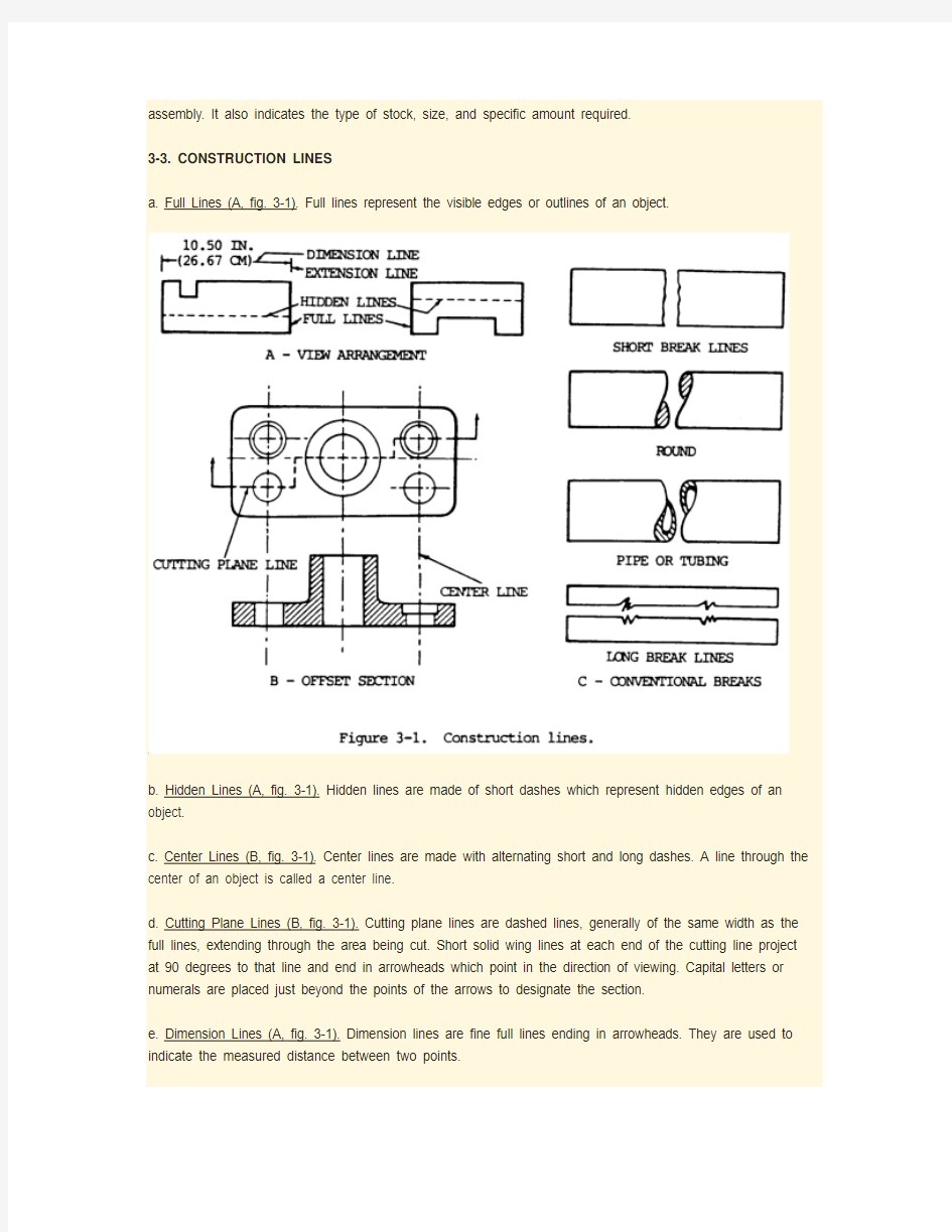
a. Full Lines (A, fig. 3-1). Full lines represent the visible edges or outlines of an object.
b. Hidden Lines (A, fig. 3-1). Hidden lines are made of short dashes which represent hidden edges of an object.
c. Center Lines (B, fig. 3-1). Center lines are made with alternating short and long dashes. A line through the center of an object is called a center line.
d. Cutting Plane Lines (B, fig. 3-1). Cutting plane lines are dashed lines, generally of the same width as the full lines, extending through the area being cut. Short solid wing lines at each end of the cutting line project at 90 degrees to that line and end in arrowheads which point in the direction of viewing. Capital letters or numerals are placed just beyond the points of the arrows to designate the section.
e. Dimension Lines (A, fig. 3-1). Dimension lines are fine full lines ending in arrowheads. They are used to indicate the measured distance between two points.
f. Extension Lines (A, fi
g. 3-1). Extension lines are fine lines from the outside edges or intermediate points of a drawn object. They indicate the limits of dimension lines.
g. Break Lines (C, fig. 3-1). Break lines are used to show a break in a drawing and are used when it is desired to increase the scale of a drawing of uniform cross section while showing the true size by dimension lines. There are two kinds of break lines: short break and long break. Short break lines are usually heavy, wavy, semiparallel lines cutting off the object outline across a uniform section. Long break lines are long dash parallel lines with each long dash in the line connected to the next by a "2" or sharp wave line.
Section II. WELD AND WELDING SYMBOLS
3-4. GENERAL
Welding cannot take its proper place as an engineering tool unless means are provided for conveying the information from the designer to the workmen. Welding symbols provide the means of placing complete welding information on drawings. The scheme for symbolic representation of welds on engineering drawings used in this manual is consistent with the "third angle" method of projection. This is the method predominantly used in the United States.
The joint is the basis of reference for welding symbols. The reference line of the welding symbol (fig. 3-2) is used to designate the type of weld to be made, its location, dimensions, extent, contour, and other supplementary information. Any welded joint indicated by a symbol will always have an arrow side and an other side. Accordingly, the terms arrow side, other side, and both sides are used herein to locate the weld with respect to the joint.
The tail of the symbol is used for designating the welding and cutting processes as well as the welding specifications, procedures, or the supplementary information to be used in making the weld. If a welder knows the size and type of weld, he has only part of the information necessary for making the weld. The process, identification of filler metal that is to be used, whether or not peening or root chipping is required, and other pertinent data must be related to the welder. The notation to be placed in the tail of the symbol indicating these data is to be establish by each user. If notations are not used, the tail of the symbol may be omitted.
3-5. ELMENTS OF A WELDING SYMBOL
A distinction is made between the terms "weld symbol" and "welding symbol". The weld symbol (fig. 3-3) indicates the desired type of weld. The welding symbol (fig. 3-2) is a method of representing the weld symbol on drawings. The assembled "welding symbol" consists of the following eight elements, or any of these elements as necessary: reference line, arrow, basic weld symbols, dimensions and other data, supplementary symbols, finish symbols, tail, and specification, process, or other reference. The locations of welding symbol elements with respect to each other are shown in figure 3-2.
3-6. BASIC WELD SYMBOLS
a. General. Weld symbols are used to indicate the welding processes used in metal joining operations, whether the weld is localized or "all around", whether it is a shop or field weld, and the contour of welds. These basic weld symbols are summarized below and illustrated in figure 3-3.
b. Arc and Gas Weld Symbols. See figure 3-3.
c. Resistance Weld Symbols. See figure 3-3.
d. Brazing, Forge, Thermit, Induction, and Flow Weld Symbols.
(1) These welds are indicated by using a process or specification reference in the tail of the welding symbol as shown in figure 3-4.
(2) When the use of a definite process is required (fig. 3-5), the process may be indicated by one or more of the letter designations shown in tables 3-1 and 3-2.
NOTE
Letter designations have not been assigned to arc spot, resistance spot, arc seam, resistance seam, and projection welding since the weld symbols used are adequate.
(3) When no specification, process, or other symbol, the tail may be omitted (fig. 3-6). reference is used with
a welding
e. Other Common Weld Symbols. Figures 3-7 and 3-8 illustrate the weld-all-around and field weld symbol, and resistance spot and resistance seam welds.
f. Supplementary Symbols. These symbols are used in many welding processes in congestion with welding symbols and are used as shown in figure 3-3.
3-7. LOCATION SIGNIFICANCE OF ARROW
a. Fillet, Groove, Flange, Flash, and Upset welding symbols. For these symbols, the arrow connects the welding symbol reference line to one side of the joint and this side shall be considered the arrow side of the joint (fig. 3-9). The side opposite the arrow side is considered the other side of the joint (fig. 3-10).
b. Plug, Slot, Arc Spot, Arc Seam, Resistance Spot, Resistance Seam, and Projection Welding Symbols. For these symbols, the arrow connects the welding symbol reference line to the outer surface of one member of the joint at the center line of the desired weld. The member to which the arrow points is considered the arrow side member. The other member of the joint shall be considered the other side member (fig. 3-11).
c. Near Side. When a joint is depicted by a single line on the drawing and the arrow of a welding symbol is directed to this line, the arrow side of the joint is considered as the near side of the joint, in accordance with the usual conventions of drafting (fig. 3-12 and 3-13).
d. Near Member. When a joint is depicted as an area parallel to the plane of projection in a drawing and the arrow of a welding symbol is directed to that area, the arrow side member of the joint is considered as the near member of the joint, in accordance with the usual conventions of drafting (fig. 3-11).
3-8. LOCATION OF THE WELD WITH RESPECT TO JOINT
a. Arrow Side. Welds on the arrow side of the joint are shown by placing the weld symbol on the side of the reference line toward the reader (fig. 3-14).
b. Other Side. Welds on the other side of the joint are shown by placing the weld symbol on the side of the reference line away from the reader (fig. 3-15).
c. Both Sides. Welds on both sides of the joint are shown by placing weld symbols on both sides of the reference line, toward and away from the reader (fig. 3-16).
d. No Side Significanc
e. Resistance spot, resistance seam, flash, weld symbols have no arrow side or other side significance in themselves, although supplementary symbols used in conjunction with these symbols may have such significance. For example, the flush contour symbol (fig. 3-3) is used in conjunction with the spot and seam symbols (fig. 3-17) to show that the exposed surface of one member of the joint is to be flush. Resistance spot, resistance seam, flash, and upset weld symbols shall be centered on the reference line (fig. 3-17).
3-9. REFERENCES AND GENERAL NOTES
a. Symbols With References. When a specification, process, or other reference is used with a welding symbol, the reference is placed in the tail (fig. 3-4).
b. Symbols Without References. Symbols may be used without specification, process, or other references when:
(1) A note similar to the following appears on the drawing: "Unless otherwise designated, all welds are to be made in accordance with specification no...."
(2) The welding procedure to be used is described elsewhere, such as in shop instructions and process sheets.
c. General Notes. General notes similar to the following may be placed on a drawing to provide detailed information pertaining to the predominant welds. This information need not be repeated on the symbols:
(1) "Unless otherwise indicated, all fillet welds are 5/16 in. (0.80 cm) size."
(2) "Unless otherwise indicated, root openings for all groove welds are 3/16 in. (0.48 cm)."
d. Process Indication. When use of a definite process is required, the process may be indicated by the letter designations listed in tables 3-1 and 3-2 (fig. 3-5).
e. Symbol Without a Tail. When no specification, process, or other reference is used with a welding symbol, the tail may be omitted (fig. 3-6).
3-10. WELD-ALL-AROUND AND FIELD WELD SYMBOLS
a. Welds extending completely around a joint are indicated by mans of the weld-all-around symbol (fig. 3-7). Welds that are completely around a joint which includes more than one type of weld, indicated by a combination weld symbol, are also depicted by the weld-all-around symbol. Welds completely around a joint in which the metal intersections at the points of welding are in more than one plane are also indicated by the weld-all-around symbol.
b. Field welds are welds not made in a shop or at the place of initial construction and are indicated by means of the field weld symbol (fig. 3-7).
3-11. EXTENT OF WELDING DENOTED BY SYMBOLS
a. Abrupt Changes. Symbols apply between abrupt changes in the direction of the welding or to the extent of hatching of dimension lines, except when the weld-all-around symbol (fig. 3-3) is used.
b. Hidden Joints. Welding on hidden joints may be covered when the welding is the same as that of the visible joint. The drawing indicates the presence of hidden members. If the welding on the hidden joint is different from that of the visible joint, specific information for the welding of both must be given.
3-12. LOCATION OF WELD SYMBOLS
a. Weld symbols, except resistance spot and resistance seam, must be shown only on the welding symbol reference line and not on the lines of the drawing.
b. Resistance spot and resistance seam weld symbols may be placed directly at the locations of the desired welds (fig. 3-8).
3-13. USE OF INCH, DEGREE, AND POUND MARKS
NOTE
Inch marks are used for indicating the diameter of arc spot, resistance spot, and circular projection welds, and the width of arc seam and resistance seam welds when such welds are specified by decimal dimensions.
In general, inch, degree, and pound marks may or may not be used on welding symbols, as desired.
3-14. CONSTRUCTION OF SYMBOLS
a. Fillet, bevel and J-groove, flare bevel groove, and corner flange symbols shall be shown with the perpendicular leg always to the left (fig. 3-18).
b. In a bevel or J-groove weld symbol, the arrow shall point with a definite break toward the member which is to be chamfered (fig. 3-19). In cases where the member to be chamfered is obvious, the break in the arrow may be omitted.
c. Information on welding symbols shall be placed to read from left to right along the reference line in accordance with the usual conventions of drafting (fig. 3-20).
d. For joints having more than one weld, a symbol shall be shown for each weld (fig 3-21).
e. The letters CP in the tail of the arrow indicate a complete penetration weld regardless of the type of weld or joint preparation (fig. 3-22).
f. When the basic weld symbols are inadequate to indicate the desired weld, the weld shall be shown by a cross section, detail, or other data with a reference on the welding symbol according to location specifications given in para 3-7 (fi
g. 3-23).
g. Two or more reference lines may be used to indicate a sequence of operations. The first operation must be shown on the reference line nearest the arrow. Subsequent operations must be shown sequentially on other reference lines (fig. 3-24). Additional reference lines may also be used to show data supplementary to welding symbol information included on the reference line nearest the arrow. Test information may be shown on a second or third line away from the arrow (fig. 3-25). When required, the weld-all-around symbol must be placed at the junction of the arrow line and reference line for each operation to which it applies (fig. 3-26). The field weld symbol may also be used in this manner.
3-15. FILLET WELDS
Dimensions of fillet welds must be shown on the same side of the reference line as the weld symbol (A, fig. 3-27).
b. When fillet welds are indicated on both sides of a joint and no general note governing the dimensions of the welds appears on the drawing, the dimensions are indicated as follows:
(1) When both welds have the same dimensions, one or both may be dimensioned (B or C, fig. 3-27).
(2) When the welds differ in dimensions, both must be dimensioned (D, fig. 3-27).
c. When fillet welds are indicated on both sides of a joint and a general note governing the dimensions of the welds appears on the drawing, neither weld need be dimensione
d. However, if the dimensions of one or both welds differ from the dimensions given in the general note, both welds must be dimensioned (C or D, fig. 3-27).
3-16. SIZE OF FILLET WELDS
a. The size of a fillet weld must of a fillet weld be shown to the left of the weld symbol (A, fig. 3-27).
b. The size the fillet weld with unequal legs must be shown in parentheses to left of the weld symbol. Weld
orientation is not shown by the symbol and must be shown on the drawing when necessary (E, fig. 3-27).
c. Unless otherwise indicated, the deposited fillet weld size must not be less than the size shown on the drawing.
d. When penetration for a given root opening is specified, the inspection method for determining penetration depth must be included in the applicable specification.
3-17. LENGTH OF FILLET WELDS
a. The length of a fillet weld, when indicated on the welding symbol, must be shown to the right of the weld symbol (A through D, fig. 3-27).
b. When fillet welding extends for the full distance between abrupt changes in the direction of the welding, no length dimension need be shown on the welding symbol.
c. Specific lengths of fillet welding may be indicated by symbols in conjunction with dimension lines (fig. 3-
28).
3-18. EXTENT OF FILLET WELDING
a. Use one type of hatching (with or without definite lines) to show the extent of fillet welding graphically.
b. Fillet welding extending beyond abrupt changes in the direction of the welding must be indicated by additional arrows pointing to each section of the joint to be welded (fig. 3-29) except when the weld-all-around symbol is used.
3-19. DIMENSIONING OF INTERMITTENT FILLET WELDING
a. The pitch (center-to-center spacing) of intermittent fillet welding shall be shown as the distance between centers of increments on one side of the joint.
b. The pitch of intermittent fillet welding shall be shown to the right of the length dimension (A, fig 3-27).
c. Dimensions of chain intermittent fillet welding must be shown on both sides of the reference line. Chain intermittent fillet welds shall be opposite each other (fig. 3-30).
d. Dimensions of staggered intermittent fillet welding must be shown on both sides of the reference line as shown in figure 3-31.
Unless otherwise specified, staggered intermittent fillet welds on both sides shall be symmetrically spaced as in figure 3-32.
3-20. TERMINATION OF INTERMITTENT FILLET WELDING
a. When intermittent fillet welding is used by itself, the symbol indicates that increments are located at the ends of the dimensioned length.
b. When intermittent fillet welding is used between continuous fillet welding, the symbol indicates that spaces equal to the pitch minus the length of one increment shall be left at the ends of the dimensioned length.
c. Separate symbols must be used for intermittent and continuous fillet welding when the two are combined along one side of the joint (fig. 3-28).
3-21. SURFACE CONTOUR OF FILLET WELDS
a. Fillet welds that are to be welded approximately flat, convex, or concave faced without recourse to any method of finishing must be shown by adding the flush, convex, or concave contour symbol to the weld symbol, in accordance with the location specifications given in paragraph 3-7 (A, fig. 3-33).
b. Fillet welds that are to be made flat faced by mechanical means must be shown by adding both the flush contour symbol and the user's standard finish symbol to the weld symbol, in accordance with location specifications given in paragraph 3-7 (B, fig. 3-33).
c. Fillet welds that are to be mechanically finished to a convex contour shall be shown by adding both the convex contour symbol and the user's standard finish symbol to the weld symbol, in accordance with location specifications given in paragraph 3-7 (C, fig. 3-33).
d. Fillet welds that are to be mechanically finished to a concave contour must be shown by adding both the concave contour symbol and the user's standard finish symbol to the weld symbol in accordance with location specification given in paragraph 3-7.
e. In cases where the angle between fusion faces is such that the identification of the type of weld and the proper weld symbol is in question, the detail of the desired joint and weld configuration must be shown on the drawing.
NOTE Finish symbols used here indicate the method of finishing (" c" = chiping, "G" = grinding, "H" = hammering, "M" = machining), not the degree of finish.
3-22. PLUG AND SLOT WELDING SYMBOLS
a. General. Neither the plug weld symbol nor the slot weld symbol may be used to designate fillet welds in holes.
b. Arrow Side and Other Side Indication of Plug and Slot Welds. Holes or slots in the arrow side member of a joint for plug or slot welding must be indicated by placing the weld symbol on the side of the reference line toward the reader (A, fig. 3-11). Holes or slots in the other side member of a joint shall be indicated by placing the weld symbol on the side of the reference line away from the reader (B, fig. 3-11).
c. Plug Weld Dimensions. Dimensions of plug welds must be shown on the same side of the reference line as the weld symbol. The size of a weld must be shown to the left of the weld symbol. Included angle of countersink of plug welds must be the user's standard unless otherwise indicate
d. Included angle of
countersink, when not the user's standard, must be shown either above or below the weld symbol (A and C, fig. 3-34). The pitch (center-to-center spacing) of plug welds shall be shown to the right of the weld symbol.
d. Depth of Filling of Plug and Slot Welds. Depth of filling of plug and slot welds shall be completed unless otherwise indicated. When the depth of filling is less than complete, the depth of filling shall be shown in inches inside the weld symbol (B, fig. 3-34).
e. Surface Contour of Plug Welds and Slot Welds. Plug welds that are to be welded approximately flush without recourse to any method of finishing must be shown by adding the finish contour symbol to the weld symbol (fig. 3-35). Plug welds that are to be welded flush by mechanical means must be shown by adding both the flush contour symbol and the user's standard finish symbol to the weld symbol (fig. 3-36).
f. Slot Weld Dimensions. Dimensions of slot welds must be shown on the same side of the reference line as the weld symbol (fi
g. 3-37).