
Rev. 0.1 12/13Copyright ? 2013 by Silicon Laboratories
AN811
AN811
S I 100X /101X TO S I 106X /108X W IRELESS MCU T RANSITION G UIDE
1. Introduction
This document provides transition assistance from the Si100x/101x wireless MCU family to the Si106x/108x wireless MCU family. The Si106x/108x represents a new generation of the wireless MCU (WMCU) family with improved performance and flexibility combined with simplicity and cost efficiency. This document is an overview comparison to highlight the main differences between these two WMCU families. It is highly recommended to read the relevant device data sheets and application notes when converting a design from Si100x/101x to Si106x/108x.
2. Benefits of the Transition
The Si106x/108x offers significantly improved radio performance in almost all areas compared to the Si100x/101x.Key among these are lower current in standby and active mode, overall improved link budget to 146dB, and improved phase noise and blocking performance. In addition, the Si106x/108x family has a highly configurable modem and packet handler to support various application requirements as well as legacy modes of operation. The Si106x/108x is packaged in a 5mm x 6mm QFN-36 package and so requires less board space than the
5mm x 7mm LGA-42 Si100x/101x. Customers will also benefit from the new development kits and WDS improvements, which make it easier to evaluate RF performance and develop application code.
3. Type Comparison
Table 1 lists the Si100x/101x family members, key properties, and recommended replacement types from the Si106x/108x family. Each replacement type contains the same CPU as the old type, combined with a new radio. In most cases, there are two replacement types listed. One contains an EZRadioPRO radio (Si446x) for maximum performance. The other contains an EZRadio radio (Si4455) with slightly limited features/performance and lower cost. Additional differences in MCU GPIO availability and internal connections are described in Section “4.Hardware Recommendations”
Table 1. WMCU Replacement Types
Old
WMCU Type Contained Radio Min VDD Flash Size Max TX Power Replacement WMCU Type
Contained Radio
Si1000Si443x 1.8V 64kB 20dBm Si1060Si4463 EZRadioPRO Si1001Si443x 1.8V 64kB 20dBm Si1061Si4463 EZRadioPRO Si1002Si443x 1.8V 64kB 20dBm Si1062Si1064Si4460 EZRadioPRO Si4455 EZRadio Si1003Si443x 1.8V 64kB 20dBm Si1063Si1065Si4460 EZRadioPRO Si4455 EZRadio Si1004Si443x 0.9V 64kB 13dBm Si1062Si1064Si4460 EZRadioPRO Si4455 EZRadio Si1005
Si443x
0.9V 64kB 13dBm
Si1063Si1065
Si4460 EZRadioPRO Si4455 EZRadio
AN811
2
Rev. 0.1
3.1. DC Characteristic Comparison
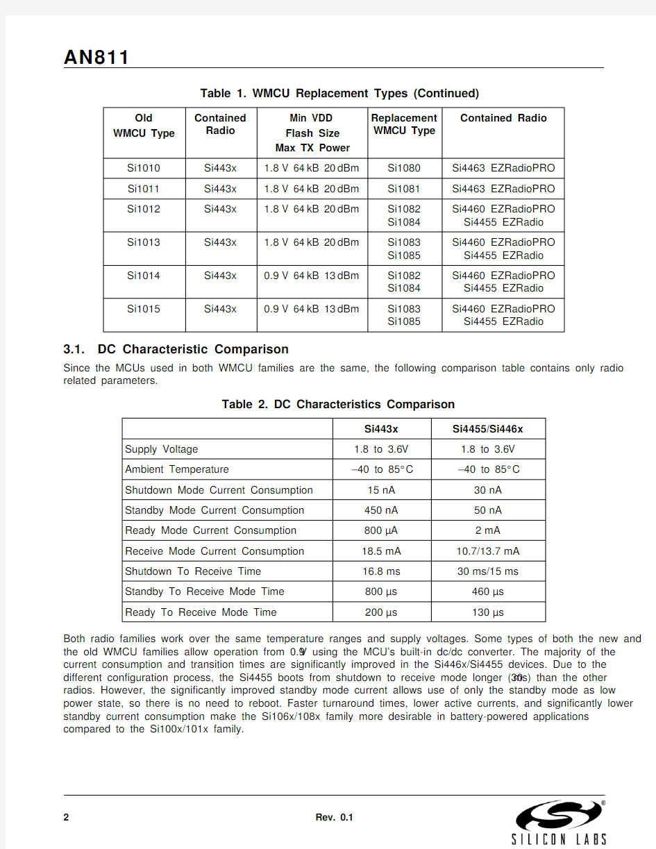
Since the MCUs used in both WMCU families are the same, the following comparison table contains only radio related parameters.
Both radio families work over the same temperature ranges and supply voltages. Some types of both the new and the old WMCU families allow operation from 0.9V using the MCU’s built-in dc/dc converter. The majority of the current consumption and transition times are significantly improved in the Si446x/Si4455 devices. Due to the different configuration process, the Si4455 boots from shutdown to receive mode longer (30ms) than the other radios. However, the significantly improved standby mode current allows use of only the standby mode as low power state, so there is no need to reboot. Faster turnaround times, lower active currents, and significantly lower standby current consumption make the Si106x/108x family more desirable in battery-powered applications compared to the Si100x/101x family.
Si1010Si443x 1.8V 64kB 20dBm Si1080Si4463 EZRadioPRO Si1011Si443x 1.8V 64kB 20dBm Si1081Si4463 EZRadioPRO Si1012Si443x 1.8V 64kB 20dBm Si1082 Si1084Si4460 EZRadioPRO Si4455 EZRadio Si1013Si443x 1.8V 64kB 20dBm Si1083 Si1085Si4460 EZRadioPRO Si4455 EZRadio Si1014Si443x 0.9V 64kB 13dBm Si1082 Si1084Si4460 EZRadioPRO Si4455 EZRadio Si1015
Si443x
0.9V 64kB 13dBm
Si1083 Si1085
Si4460 EZRadioPRO Si4455 EZRadio
Table 2. DC Characteristics Comparison
Si443x
Si4455/Si446x Supply Voltage 1.8 to 3.6V 1.8 to 3.6V Ambient Temperature
–40 to 85°C –40 to 85°C Shutdown Mode Current Consumption 15nA 30nA Standby Mode Current Consumption 450nA 50nA Ready Mode Current Consumption 800μA 2mA Receive Mode Current Consumption 18.5mA 10.7/13.7mA Shutdown To Receive Time 16.8ms 30ms/15ms Standby To Receive Mode Time 800μs 460μs Ready To Receive Mode Time
200μs
130μs
Table 1. WMCU Replacement Types (Continued)
Old
WMCU Type Contained Radio Min VDD Flash Size Max TX Power Replacement WMCU Type
Contained Radio
AN811
Rev. 0.1
3
3.2. RF Parameters Comparison
The wider range of operating frequencies allows the Si446x family to be used in 169MHz European ISM Bands (proprietary, social alarm, or Wireless MBUS N mode applications). The narrower Receive channel filter, better sensitivity, and excellent blocking performance make the Si446x more valuable in narrow-band applications (FCC Part 90, ETSI Category 1, etc.). The Si4455 targets certain applications where the narrow band operation and the full frequency coverage are not requirements.
Table 3. RF Parameters Comparison
Si443x
Si4460/Si4463
Si4455
Frequency range
240 to 480MHz (156.25Hz res.)480 to 960MHz (312.5Hz res.)142–175MHz (4.7Hz res.)283–350MHz (9.5Hz res.)420–525MHz (14.3Hz res.)
850–1050MHz (28.6Hz
res.)
283 to 350MHz (38.1Hz res.)425 to 525MHz (57.2Hz res.)
850 to 960MHz (114.4Hz res.)RX Channel BW
2.6 to 620kHz 1.1 to 850kHz
40 to 850kHz
RX sensitivity –108dBm (40kbps, GFSK, ±20kHz dev., BER<0.1%)
–110dBm (40kbps, GFSK, +-20kHz dev., BER<0.1%))
–108dBm (40kbps, GFSK, ±25kHz dev., BER <0.1%)
Blocking 1MHz Offset
–52dBm
–75dBm
–61dBm
AN811
4
Rev. 0.1
4. Hardware Recommendations
Due to the different package and pinout, it is necessary to modify the application printed circuit board when transitioning from the Si100x/101x to the Si106x/108x. The following sections summarize the main differences and provide guidelines for component selection.
4.1. Package and Pinout
The Si106x/108x is packaged in a 5mm x 6mm QFN-36 package and so requires less board space than the
5mm x 7mm LGA-42 packaged Si100x/101x. There are also differences in the pinout of the devices that is summarized in the next table.
The following table compares the pinout of all devices. Pin functions that are available on every WMCU are not listed. Signal names in parenthesis are connected inside the WMCU package and not available externally.
Table 4. Pinout Difference Summary
Si100x/101x
Si106x/108x MCU P1.7 and P2.0-6Available on some types Not available
Radio NSS pin
Connected to P1.4 or P1.3 internally
Connected to P1.3 internally Radio SDN pin and MCU GPIO P0.7
Available externally
Connected together internally Radio general purpose IOs
3 radio GPIOs (digital signals or ana-log input for the internal ADC)
4 radio GPIOs (digital signals or analog input for the internal
ADC)ANT Pin
ANT pin can control the RF switch in an antenna diversity application. It helps to utilize the GPIOs for other
purposes.
The RF switch control function-ality is available on all 4 GPIOs. It provides flexibility for the HW designer to select GPIOs for RF switch control purposes that result in the most optimal RF
layout.TXRAMP Pin This feature is not available
Available on some types.TXRamp pin can be used to control the TX ramp-up of the front end module or provide bias for the external transistor in a high-output power design.
VR_DIG Pin
Regulated output voltage of the radio digital LDO. Cannot be loaded exter-nally. 1μF decoupling capacitor needs
to be connected to this pin.
No need for capacitor on output of internal LDO (so not available
externally).
AN811
Rev. 0.1
5
Table 5. Pinout Comparison
Si1000/1/2/3Si1004/5Si1010/1/2/3Si1014/5Si1060/1 Si1080/1
Si1062/3 Si1082/3Si1064/5 Si1084/5—VBAT
—
VBAT
—
VBAT VBAT —GND/VBAT-—GND/VBAT-—GND/VBAT-GND/VBAT-—DCEN —DCEN —
DCEN DCEN P0.7P0.7P0.7P0.7
(P0.7/SDN)
(P0.7/SDN)(P0.7/SDN)—
—
(P1.3/NSS)
(P1.3/NSS)(P1.3/NSS)(P1.3/NSS)(P1.3/NSS)(P1.4/NSS)(P1.4/NSS)P1.4P1.4P1.4P1.4P1.4P1.7P1.7—————P2.0P2.0—————P2.1P2.1—————P2.2P2.2—————P2.3P2.3—————P2.4——————P2.5——————P2.6——————————GPIO_3GPIO_3GPIO_3SDN SDN SDN SDN ———————TXRAMP TXRAMP —ANT_A ANT_A ANT_A ANT_A ———VDD_DIG VDD_DIG VDD_DIG VDD_DIG ———VR_DIG
VR_DIG
VR_DIG
VR_DIG
—
—
—
AN811
6
Rev. 0.1
4.2. Reference Design, Component Selection
The typical application circuit for the Si100x WMCU is shown in Figure1, and the typical application circuit for the Si106x/8x WMCU is shown in Figure2.
Figure1.Si100x Application Example
Figure2.Si106x Application Example
The architecture of the Receive and Transmit frontends of both radios are similar; therefore, the matching network topologies are the same in both application examples. Both radios can support different TX matching network topologies. Refer to the following application notes for more details and comparisons of the different topologies:
? AN627: Si4060/Si4460/61 Low-Power PA Matching
? AN648: Si4063/4463/64 TX Matching
? AN693: Si4455 Low-Power PA Matching
The Si4455/Si446x can run on the same crystal as the Si443x. To utilize a lower-cost crystal in the application, the Si4455/Si446x is designed to accommodate a wide range of crystal frequencies (25–32MHz). Refer to “AN785: Crystal Selection Guide for the Si4x6x RF ICs” for more details on crystal or TCXO selection for the Si4455/Si446x devices.
AN811
Rev. 0.17
5. Firmware Recommendations
5.1. Configuration Interface
The radios in both WMCU families can be configured through standard SPI interface, with up to 10MHz clock speed.
The SPI interfaces of the radio and MCU are connected internally in the WMCU package. The differences in connection of the NSS and SDN signals (described in the previous chapter) has to be followed in the firmware also.An Application Programming Interface (API) is designed for the radios in the Si106x/108x devices over the SPI interface instead of using a register configuration approach like in the Si100x/101x. The major benefit of the API is that the radio can execute complex commands and procedures with minimal MCU interaction. This approach helps reduce the time-critical tasks of the MCU. However, using the API also has some drawbacks:
? The command execution time varies from command to command, and it may take more time than changing
a simple register in the case of very basic commands.
? Retrieving status information from the chip requires the following process: issue a command that
addresses what information the MCU is asking for; wait for the radio to prepare the data (wait for the Clear To Send Signal), and read the actual status information.
For time-critical information, the MCU can access the Fast Response Registers (RSSI, interrupt status, etc.) or use dedicated HW commands (Transmit FIFO Write, Receive FIFO Read) as well. The complete list of commands and their descriptions are provided in HTML documents in “EZRadioPRO API Documentation” and “EZRadio API Documentation” zip files that are available on the Silicon Labs web site at https://www.doczj.com/doc/73193778.html, . The HTML format helps to navigate more easily within the document. The open/collapse feature of the HTML document also helps to highlight or hide desired or undesired details for easier readability.
5.2. Radio Power-On Sequence and Configuration
After waiting for the Power-On Reset, the radio in the Si100x/101x is ready to receive configuration commands.The radio can be initialized by overwriting registers that need to be different than their default value. The value of the registers needs to be defined by the user based on the data sheet; therefore there is a chance to overlook a necessary setting that results in unwanted radio behavior.
For the radio in the Si106x/108x, an additional step of sending a power up command is required because the radio needs to boot up before it is ready to receive configuration commands. Following the boot up, configuration commands can be sent to the radio according to the desired radio parameters. The desired parameters are set on a graphical interface of the WDS PC software, which means that configuration commands are generated by the WDS rather than by the user.
The WDS provides the ability to pick-up predefined, tested radio settings for customers who are not familiar with RF tradeoffs. The WDS also allows the flexibility to configure any desired radio configuration. The configuration commands are generated by the WDS in the form of a config header file.
For the Si1064/5 and Si1084/5 devices, which have EZRadio radios, most of the configuration settings are organized into an array. The consistency of the array is protected with CRC and the array is encoded to prevent bit-by-bit changes and the possibility of missing an important configuration setting. The size of the configuration array is 212 bytes, which need to be stored in the host MCU and may increase the code size compared to the other WMCUs’ application code.
The configuration array stores all the settings that are typically set during initialization:
? Radio configuration: crystal parameters, frequency band, modulation format, data rate, etc.? Packet content related settings: preamble, synchron word, CRC, etc.
? Operation mode: packet-based communication or direct data reception on a GPIO
If the application requires a change in any of the above settings during run-time, then the radio needs to be reset (toggling the SDN pin) and a new configuration array needs to be sent to the radio.
In addition to the configuration array, there are settings that can be changed even after the configuration array is sent to the radio. These settings include fine-tuning parameters (e.g., crystal frequency fine tuning registers),center frequency, channel spacing, packet content related or interrupt related settings.
AN811
8
Rev. 0.1
Figure 3.Radio Initialization Process for the WMCUs
For more information about the WDS and the configuration array, refer to the Programming Guides and Sample Codes.
5.3. Typical Use Cases
Both WMCU families support the typical use cases: transmitting and receiving packets or transmitting and receiving data in direct mode (when the data is available or provided through a GPIO instead of via the FIFO). Due to the API interface of the radios in the Si106x/108x WMCUs, realizing the typical use cases is different than that for the Si100x/101x WMCUs. The SPI low-layer driver and the high level application logic can be kept; the rest of the application code needs to be changed.
Both radios have a programming guide with example codes summary showing how the radio needs to be used. In addition to the improved radio operation, there are also major improvements in the example projects and the Si106x/108x support tools as well:
? The Si100x/101x example codes are very basic, not partitioned, and therefore a bit difficult to change and
port them to another HW platform. The Si106x/108x example projects are built based on a driver set that is well partitioned and beside the radio it supports all major peripherals of the evaluation boards too.
? The radio configuration of the Si100x/101x example codes need to be configured manually. WDS has a new feature for the Si106x/108x devices: it can generate example projects with customized radio settings and packet configuration. The projects can be saved or opened in the Silicon Labs IDE for further FW development, which reduces the possibility of misconfiguration of the radio and provides complete, tested C source code for the given use case. It drastically reduces the development time.
For more details refer to the application notes, “AN692: Si4355/4455 Programming Guide” and “AN633:Programming Guide for EZRadioPRO Si4x6x Devices” for more details on the example projects.
Si100x/101x radio initialization
AN811
Rev. 0.1
9
5.4. RX Modem
Both radios use high-performance ADCs that allow channel filtering, image rejection, and demodulation to be performed in the digital domain. The Si4455/Si446x has an improved digital modem; the differences are summarized in Table 6.
Table 6. RX Modem Comparison
Specification Si443x Si446x
Si4455Modulation Modes 2GFSK, 2FSK, OOK 2GFSK, 2FSK, 4GFSK, 4FSK,
GMSK, OOK
2GFSK, 2FSK, OOK
(G)FSK Data Rate 0.123–256kbps
0.1–500kbps 1.0-500kbps
4(G)FSK Data Rate N/A 0.2–1000kbps N/A OOK Data Rate 0.123–40kbps 0.1–120kbps
0.5–120kbps RX Architecture Fixed-IF (937.5kHz)
Fixed-IF (Fxtal/64), zero-IF,
scaled-IF Fixed-IF (Fxtal/64)
Image Calibration
N/A
Image calibration (IRCAL API com-mand) is available to improve the image rejection to more than 55dB
in fixed-IF mode.N/A
RSSI
Current RSSI can be read from a register.
The current RSSI is available through API call or Fast Response
Registers.
RSSI can be latched and stored upon a system event (preamble/synch word detection, etc.). For more accurate RSSI reading, the radio can average it for various bit
timings.
The radio can provide an interrupt if the RSSI is changed by a program-mable amount during packet recep-tion to detect interfering signals.
The current RSSI is avail-able through the GET_MODEM_STATUS API command. RSSI is latched upon synch word detection and the latched value can be read through Fast Response Register. The radio can provide an interrupt if the RSSI exceeds a programmable
threshold value.
Preamble Detection
RX chain settles and detect standard pre-amble (“0101”).RX chain settles and detects stan-dard (up to 256bytes) and custom preamble pattern (up to 4 bytes).RX chain settles and detects standard (up to 256 bytes) preamble ("0101").
AN811
10
Rev. 0.1
The wider data rate and modulation format support make the Si446x more future proof. The extremely-configurable RX modem makes it possible to design-in the Si446x for legacy product replacement.
Image calibration in fixed-IF mode allows the use of Si446x radios in ultra-narrow-band applications. Refer to “AN790: Image Rejection and IQ Calibration” for more details on image calibration.
Automatic RX Hop-ping and Hop Table
N/A
This feature is intended for RX hop-ping where the device has to hop from channel to channel and look for packets.
It is fully-configurable through the API interface, including hop table and hop conditions.
N/A
Manual RX Hopping N/A It provides a fast turnaround time (75μs) from RX-to-RX that can be utilized for frequency scanning algo-rithms.
N/A
Table 6. RX Modem Comparison (Continued)
Specification Si443x Si446x
Si4455
AN811
Rev. 0.1
11
5.5. Packet Handler
Both radios have built-in packet handlers that help to process the received data bits and construct the transmit packets. Utilizing this feature offloads these time-consuming tasks from the host MCU and allows for the selection of a simpler, lower-cost MCU.
The CRC and data-Whitening seeds and polynomials are more configurable in the Si446x than in the Si443x and Si4455.
5.5.1. Receive Packet Handler
The Receive packet handler operation of the Si443x and Si4455 is very basic compared to that of the Si446x.While the Si443x and Si4455 support only fixed or variable packet length mode operation with optional CRC,Manchester coding, and data Whitening over the entire packet, the Si446x can be configured for a wide variety of packet configurations by introducing the FIELD feature.
FIELD is an entity within the packet where the CRC, Manchester coding, and data Whitening settings are fixed within that entity. The FIELD feature is also mandatory if 4(G)FSK modulation is used. Up to five FIELDs can be configured within a packet. One of the FIELDs can be of variable length, where the length byte must be present in an earlier FIELD.
Figure 4.Packet Handler Operation of the Si446x
5.5.2. Transmit Packet Handler
The Si443x can be configured for fixed or variable-length packet transmissions. In fixed packet length mode, the radio transmits the preamble and the synch word automatically followed by the desired number of bytes from the TX FIFO. The radio also automatically applies the selected CRC calculation, Manchester coding, or data Whitening features over the entire packet.
In variable packet length mode, the operation is similar, but there is a length byte transmitted by the radio right after the synchron word that determines how many bytes will be transmitted from the FIFO.
The Si4455 and Si446x do not have dedicated variable packet length mode operation. The entire packet has to be filled into the FIFO as it desired to be transmitted, including the length byte on the proper location. Next, the START_TX command has to be called with the packet length to initiate the packet transmission. The radio transmits the preamble and the sync word automatically followed by the desired number of bytes from the FIFO (defined as packet length in the START_TX command).
AN811
12
Rev. 0.1
5.6. Auxiliary Functions
Table 7 summarizes the auxiliary functions of the radios in the WMCUs:
The Si106x/108x has a different radio power-on reset circuit with reduced Standby mode current consumption. It cannot reset the radio upon rising edge of the supply voltage (called smart reset in Si100x/101x). Refer to the Si106x/108x data sheet for more details on the radio power-on reset.
Note:If you wish to reset the radio from the host MCU, the SDN pin is intended to be used for that purpose.
The Radio Wake-up Timer (that can wake up the radio and the host MCU regularly to complete scheduled tasks)has a new feature in the Si1060/1/2/3 and Si1080/1/2/3 devices. It not only provides Low Duty Cycle Reception (LDC RX), but also Low Duty Cycle Transmission (LDC TX).
In the Si106x/108x devices, there is an 11-bit auxiliary ADC for measuring the battery voltage or an external voltage over a GPIO. The Si1060/1/2/3 and Si1080/1/2/3 also has an internal temperature sensor. The ADC utilizes SAR architecture and achieves 11-bit resolution. The Effective Number of Bits (ENOB) is 9 bits. This is an improvement over the 8-bit SAR architecture of the Si100x/101x devices.
The RSSI can be read from a register in case of the Si100x/101x WMCUs, while it is in Receive mode. In the Si106x/108x, the RSSI is accessible through the fast response register. In addition to being able to read the RSSI any time during receive mode, Si106x/108x has a new feature to latch and store the RSSI value upon certain conditions. This feature helps to offload the host MCU from time critical tasks:
? If a frequency scan algorithm needs to be designed that is based on RSSI measurements, then it is
recommended to latch the RSSI a few bits time later than the receiver has settled. This method provides a fast way to measure the energy on all frequency channels.
? If the application requires knowing the signal strength of the incoming packet, then it is recommended to latch the RSSI upon preamble or synch word detection.
Both WMCU families can generate an interrupt if the RSSI exceeds a threshold any time during receive mode.The Wake-up Timer, the Temperature sensor and the MCU Clock Output are not available in the Si1064/5 and Si1084/5 devices, but the MCU SmaRTClock and Temperature sensor can be used instead. An example project is available in WDS that implements the LDC mode in the host MCU.
Table 7. Auxiliary Functions
Radio auxiliary
function Si100x Si101x Si1060/1/2/3Si1080/1/2/3Si1064/5 Si1084/5
Power On Reset Smart Reset
Simple Power On-Reset
Simple Power-On Reset Low Battery Detect
Battery voltage read
Low Battery Threshold Inter-rupt Battery voltage read Low Battery Threshold Inter-rupt Battery voltage read Low Battery Threshold
Interrupt
Clock Out for MCU Derived from the XTAL Derived from the XTAL Not available RSSI
Actual value during recep-tion
RSSI Threshold Interrupt
Actual and latched value
during reception RSSI Threshold Interrupt
Actual and latched value
during reception RSSI Threshold Interrupt Temperature Sensor Available through the ADC of the radio Available through the ADC of
the radio Available in the MCU Wake Up Timer
Programmable, runs from the 32kHz RC oscillator Has LDC RX feature
Programmable, runs from the
32kHz oscillator
Has LDC RX and LDC TX
feature
Not available in the radio.MCU can wake up the radio using SmaRTClock
AN811
Rev. 0.1
13
C ONTACT I NFORMATION
Silicon Laboratories Inc.400 West Cesar Chavez Austin, TX 78701
Tel: 1+(512) 416-8500Fax: 1+(512) 416-9669
Toll Free: 1+(877) 444-3032
Please visit the Silicon Labs Technical Support web page:
https://https://www.doczj.com/doc/73193778.html,/support/pages/contacttechnicalsupport.aspx and register to submit a technical support request.
Patent Notice
Silicon Labs invests in research and development to help our customers differentiate in the market with innovative low-power, small size, analog-intensive mixed-signal solutions. Silicon Labs' extensive patent portfolio is a testament to our unique approach and world-class engineering team.
Silicon Laboratories and Silicon Labs are trademarks of Silicon Laboratories Inc.
Other products or brandnames mentioned herein are trademarks or registered trademarks of their respective holders.
The information in this document is believed to be accurate in all respects at the time of publication but is subject to change without notice. Silicon Laboratories assumes no responsibility for errors and omissions, and disclaims responsibility for any consequences resulting from the use of information included herein. Additionally, Silicon Laboratories assumes no responsibility for the functioning of undescribed fea-tures or parameters. Silicon Laboratories reserves the right to make changes without further notice. Silicon Laboratories makes no warran-ty, representation or guarantee regarding the suitability of its products for any particular purpose, nor does Silicon Laboratories assume any liability arising out of the application or use of any product or circuit, and specifically disclaims any and all liability, including without limitation consequential or incidental damages. Silicon Laboratories products are not designed, intended, or authorized for use in applications intend-ed to support or sustain life, or for any other application in which the failure of the Silicon Laboratories product could create a situation where personal injury or death may occur. Should Buyer purchase or use Silicon Laboratories products for any such unintended or unauthorized application, Buyer shall indemnify and hold Silicon Laboratories harmless against all claims and damages.