Development of a conjugated polyaniline incorporated electrospun
poly(vinylidene fluoride-co-hexafluoropropylene)composite membrane electrolyte for high performance dye-sensitized solar cells
Vijayakumar Elayappan,1Vignesh Murugadoss,1Subramania Angaiah,1Zhaofu Fei,2Paul J.Dyson2 1Electrochemical Energy Research Lab,Centre for Nanoscience and Technology,Pondicherry University,Puducherry605014,
India
2Institut des Sciences et Ing e nierie Chimiques,Ecole Polytechnique F e d e rale de Lausanne(EPFL)CH-1015,Lausanne,
Switzerland
Correspondence to:S.Angaiah(E-mail:a.subramania@https://www.doczj.com/doc/6017728341.html,)
ABSTRACT:Different weight percentage(2,3,4,and5wt%)of polyaniline(PANI)were incorporated into electrospun poly(vinyli-dene fluoride-co-hexafluoropropylene)(PVdF-HFP)composite membranes(esCPMs).The regular morphology,molecular structure, crystallinity,porosity,electrolyte uptake,and leakage of the composite membranes were examined.The esCPMs were activated in liq-uid electrolyte containing0.5M LiI,0.05M I2,and0.5M4-tert-butylpyridine and0.5M1-butyl-3-methylimidazoliun iodide in ace-tonitrile to afford electrospun PVdF-HFP/PANI composite membrane electrolytes(esCPMEs).The influence of different wt%of PANI on the esCPMEs was studied by electrochemical impedance measurements and Tafel polarization studies.The photovoltaic per-formance of a dye-sensitized solar cell assembled using3wt%PANI incorporated esCPME exhibits a higher power conversion effi-ciency of7.20%than that assembled using esPME(g56.42%).V C2015Wiley Periodicals,Inc.J.Appl.Polym.Sci.2015,132,42777. KEYWORDS:composites;electrochemistry;fibers;membranes;photochemistry
Received2June2015;accepted23July2015
DOI:10.1002/app.42777
INTRODUCTION
Dye-sensitized solar cells(DSSCs)are among the most exten-sively investigated devices that provide a high light-to-electric energy conversion devices.1One of the critical components of DSSCs is the electrolyte which contains redox couple,often I2/ I23to meditate the dye regeneration process and the devices containing liquid electrolytes have achieved high light to power conversion efficiency(PCE)of about12%.2Nevertheless,sol-vent evaporation and leakage of liquid electrolytes desorption of weakly adsorbed dyes and corrosion of electrodes can be prob-lematic.It would therefore be advantageous to replace the liquid electrolytes.Among the various alternatives such as ionic liquids,3,4P-type semiconductors,5ionic conducting polymers,6 organic hole transport polymers,7and polymer gel electrolytes,8 polymer membrane electrolyte containing I2/I23redox couple attracts great attention due to its higher ionic conductivity and an excellent long-term stability towards DSSCs.Recently, electrospun polymer membrane containing ionic liquid has attracted remarkable interest.9–12Among the techniques avail-able for the preparation of polymer membranes,electrospinning is a simple and versatile,and has a high degree of reproducibil-ity.Electrospun membranes provide better electrolyte uptake because of their three-dimensional network with interconnected pores.Hence,the ionic conductivity of electrospun polymer membrane electrolyte is usually high compared with that of other conventional polymer membrane electrolyte.These inter-connected pores are able to trap the liquid electrolyte and con-sequently,the resulting esPMEs appears to act as a liquid as well as a gel electrolyte.Conductive polymers such as polyani-line(PANI),polypyrrole,polythiophene,polyacetylene,and so on,show potential applications in DSSCs because of their unique properties,such as inexpensiveness,high-conductivity, good stability,and catalytic activity for I23reduction.13–18 Among various conducting polymers,PANI is an excellent one with more advantages such as low cost,easy synthesis,high-conductivity,good environmental stability,and interesting redox properties.19–21Herein,we describe an approach to improve ion transport in polymer membrane electrolyte by inclusion of the conjugated PANI due to its controllable electrical conductivity, environmental stability,and relevant redox properties.20,22 Indeed,a conducting PANI incorporated polymer gel electrolyte was reported recently that exhibits good electrical conduction
V C2015Wiley Periodicals,Inc.
behavior.23In presence of PANI,the superior electrocatalytic activity towards I 2/I 23redox reaction and an increased ionic conductivity and electron transport were observed.24The inclu-sion of PANI in a polymer gel was shown to accelerate the mobility of charge carriers in the electrolyte so that the triodide can migrate rapidly to the Pt-coated counter electrode and be efficiently reduced at the counter electrode,instead of the recombination with the titania anode.25In addition,the integra-tion of conjugated structure of PANI can shorten the charge dif-fusion path length and more importantly,the conjugated PANI structure participates in the dye regeneration by hole injection into the PANI.19Among the numerous polymer matrices studied,the vinylidene fluoride-hexafluoropropylene copolymer is of con-siderable interest because it has relatively lower crystallinity com-pared with other polymer matrices.26However,the PANI incorporated electrospun poly(vinylidene fluoride-co -hexafluoro-propylene)(PVdF-HFP)membrane electrolyte for DSSC has not been studied yet.The electrospun polymer membrane is activated by liquid electrolyte as they provide the advantages of nonvolatility,thermal stability,as well as high ionic
conductivity.Hence,in this investigation,different weight per-centage of PANI incorporated electrospun PVdF-HFP composite membranes are activated with a liquid electrolyte and the influ-ence of PANI on photovoltaic performance are studied in detail.
EXPERIMENTAL
Materials
PANI nanoparticles were prepared as per the literature.6Acetone and N ,N 0-dimethylacetamide were procured from Merck India Ltd.Lithium iodide,iodide,4-tert -butylpyridine,and acetonitrile were procured from Sigma Aldrich and PVdF-HFP from Arkema (Kynar flex 2801).All these chemicals are analytical grade and used as received without any further purification.
Preparation of esCPMs
The electrospun PVdF-HFP/PANI composite membranes were prepared using 16wt %of PVdF-HFP solution in a mixture of acetone/N ,N 0-dimethyl acetamide (7:3wt %)containing differ-ent weight percentage of PANI (2,3,4,and 5wt %)with respec-tive to PVdF-HFP .The resulting polymer solution was supplied to the stainless steel syringe needle (27G)using a syringe pump at a flow rate of 0.5mL/h.The electrospinning was carried out at the voltage of 19kV and the distance between the collector and tip of the needle was kept at 12cm.The resulting nanofibrous membrane was vacuum dried at 808C for 12h to remove residual solvent.The thickness of electrospun PVdF-HFP composite membranes (esCPMs)was reduced from about 30to 20m m by hot pressing.10
Characterization of esCPMs
The surface morphology of esCPMs was examined by field emis-sion scanning electron microscopy (FE-SEM;Model:JSM-7600F).Structural characterization of esCPMs was studied by X-ray diffraction (Rigaku,Ultima IV)with nickel-filtered Cu-K a radiation in the range of 208–808with an increment of 0.058.Thermal behavior of esCPMs 27was measured using differential scanning calorimetric (DSC;TA Instruments,Model:Q600SDT)at a heating rate of 108C/min under nitrogen atmosphere in the temperature range of 30–2008
C.
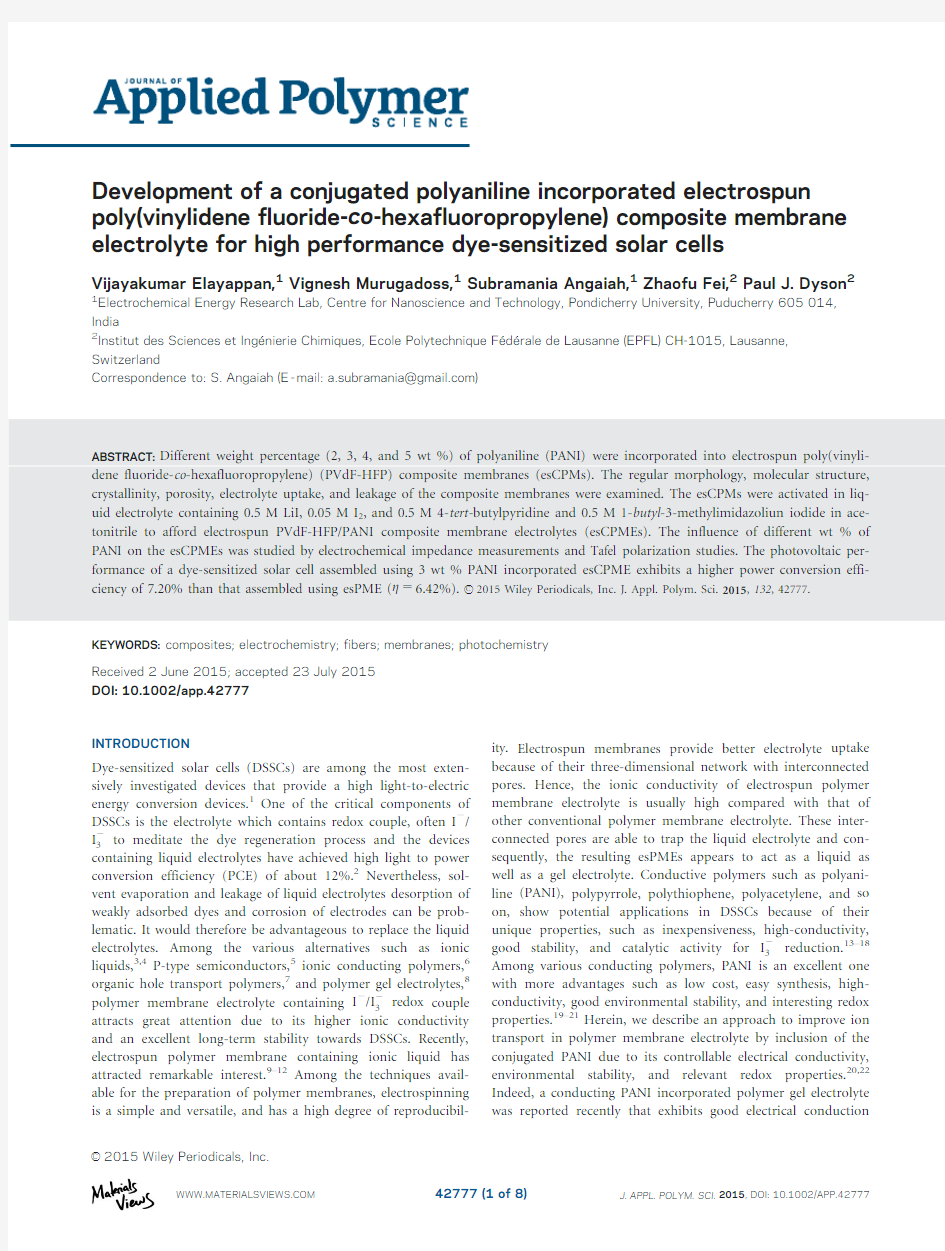
Figure 1.FE-SEM images of (a)esPM and (b)3wt %PANI incorporated
esCPM.
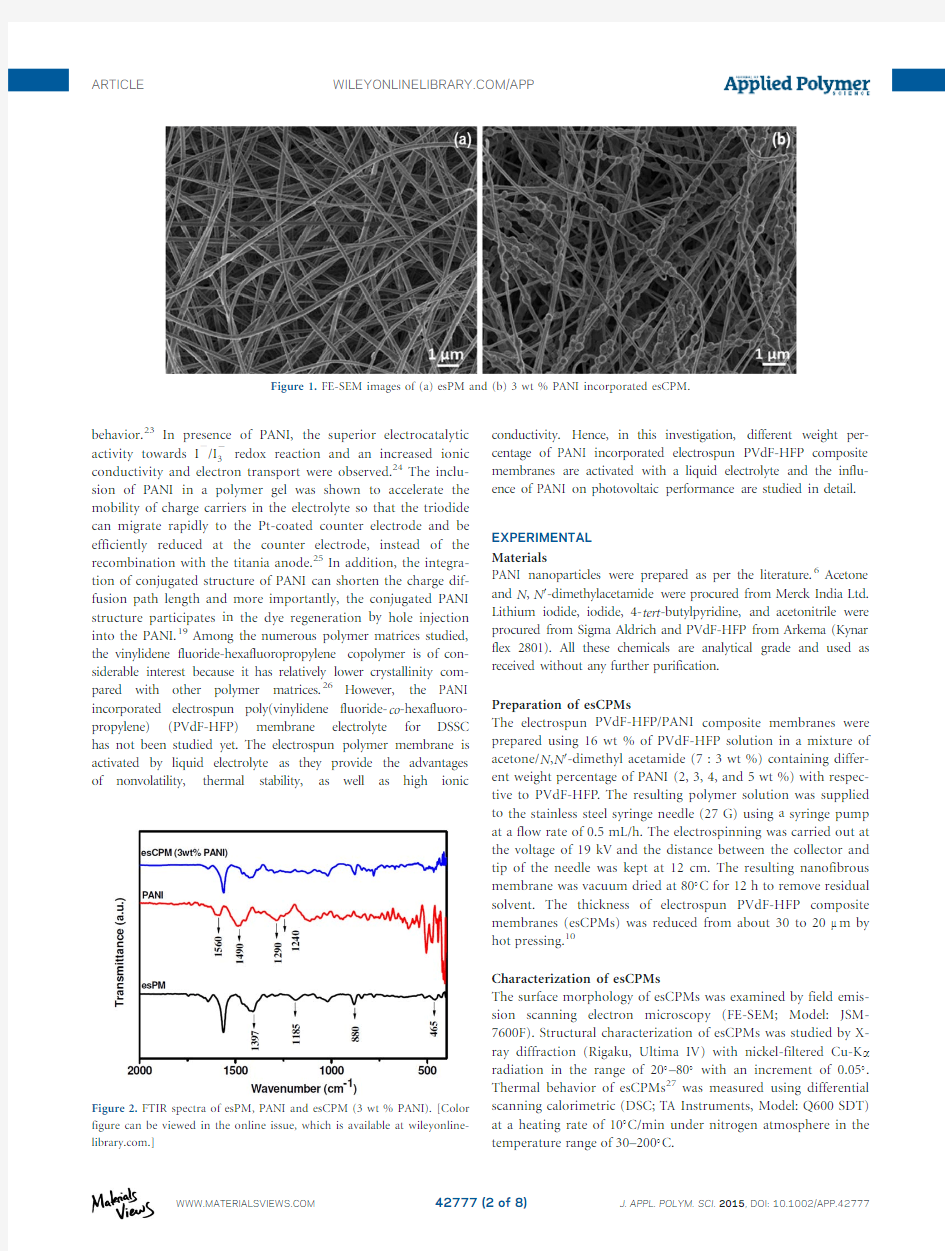
Figure 2.FTIR spectra of esPM,PANI and esCPM (3wt %PANI).[Color figure can be viewed in the online issue,which is available at https://www.doczj.com/doc/6017728341.html,.]
The crystallinity (X c )of the esCPMs was calculated as follows 8
X c %eT5
D H sample m
D H m
3100(1)
where D H sample m is the heat of melting of the sample and D H ?
m is the crystalline melting heat of PVdF,104.7J/g.
The porosity (P )of esCPMs was determined by weighing the membrane with and without 1-butanol from the following equation 28
P 5
m a =q a
m a =q a 1m p =q p
(2)
where m a is the weight of esCPM after impregnation with 1-butanol,m p is the weight of esCPM before impregnation with
1-butanol,and q a and q p are density of 1-butanol and the dried esCPM,respectively.
To measure the electrolyte uptake of both esPM and esCPMs,the membranes were soaked in the liquid electrolyte for 24h.They were then taken out from the liquid electrolyte solution and the excess electrolyte solution on the membrane was wiped off using whatman filter paper.Electrolyte uptake (U )was estimated using
U e%T5?em 2m T=m 3100
(3)
where,m and m o are the mass of wet and dry electrospun esCPMs,respectively.29
The leakage of electrolyte was calculated using
R 5
M PE
M PE ;saturated
(4)
where,R is the relative absorption ratio of liquid electrolyte,M PE,-saturated is the mass of esCPME when the membrane is fully satu-rated with the liquid electrolyte and M PE is the mass of esCPME after a time interval when the saturated polymer membrane elec-trolyte is squeezed by pressing it between the filter papers.30The different esCPMs were soaked in the liquid electrolyte to form their corresponding esCPMEs.The ionic conductivity (r )of resulting esCPMEs was measured by sandwiching the esCPME between two stainless steel blocking electrodes and recorded their AC-impedance spectra (Biologic Model:VSP)at 258C.The ionic conductivity of esCPME was calculated using the equation 31
r 5‘=RA
(5)
where ‘is the polymer membrane thickness,A is the area of the electrospun PVdF-HFP/PANI composite membrane electro-lyte,and R is the bulk resistance.The frequency limit was set between 1mHz and 100KHz with an AC amplitude of 10mV.The thickness (‘)of esCPME was determined using a dig-ital micrometer (Mitutoyo,Japan)and was found to be 20l m.The area (A )of the polymer membrane electrolyte was 1cm 2
.
Figure 3.XRD patterns of PVdF-HFP powder,PANI,esPM,and different wt %PANI incorporated esCPMs.[Color figure can be viewed in the online issue,which is available at
https://www.doczj.com/doc/6017728341.html,.]
Figure 4.DSC curves of esPM and 3wt %PANI incorporated esCPM.[Color figure can be viewed in the online issue,which is available at
https://www.doczj.com/doc/6017728341.html,.]Figure 5.Nyquist plots for esPME and different wt %of PANI incorpo-rated esCPMEs on ionic conductivity.[Color figure can be viewed in the online issue,which is available at https://www.doczj.com/doc/6017728341.html,.]
DSSC Fabrication
A detailed procedure to assemble the DSSC was reported previ-ously.32The DSSC containing the esCPME was assembled by sandwiching a slice of esCPME between a dye-sensitized std.TiO 2photoanode and standard Pt counter electrode.The dye adsorbed TiO 2photoanode and Pt counter electrode were assembled using a 60l m thick hot melt thermoplastic sealer (Surlyn).33A required amount of the electrolyte containing 0.5M LiI,0.05M I 2and 0.5M 4-tertbutylpyridine and 0.5M 1-butyl -3-methylimidazoliun iodide in acetonitrile 10was injected into the clamped electrodes through one of two small holes drilled in the counter electrode.Similarly,a control DSSC based on esPME was also assembled for comparison.
Photovoltaic Performance of DSSCs
The photovoltaic performance of DSSCs was determined by using a calibrated AM 1.5solar simulator (Newport,Oriel instruments,Model:67005)with a light intensity of 100mW cm 22and a computer controlled digital source meter (Keithley,model:2420).I–V measurements were carried out on the DSSCs after an aging period of 24h.The DSSCs were stored in a desiccator and measurements were made for every 48h to determine their long-term stability.Photoelectrochemical parameters including the fill factor (FF )and PCE (g )were cal-culated using the following equations 32
g e%T5V max J max P in
31005V oc J sc FF
P in 3100(6)
FF 5
V max J max V oc J sc
(7)
where J sc is the short-circuit current density (mA cm 22),V oc is
the open-circuit voltage (V),P in is the incident light power (mW cm 22),and J max and V max are the current density (mA cm 22)and voltage (V)in the J-V curves,respectively,at the point of maximum power output.All the fabrication steps and characterization measurements were carried out in an ambient environment without a protective atmosphere.The photovoltaic parameter values were obtained from the average values of three DSSC devices.
RESULTS AND DISCUSSION
Characterization of esCPMs and esCPMEs
The morphologies of the esPM and esCPM (3wt %of PANI)are shown in Figure 1(a,b).They comprise fibers with a uni-form size distribution and well defined structure.The average fiber diameter of esPM is 300–400nm and the esCPM is 300–350nm.Notably,the FE-SEM image of the esCPM shows addi-tional particles that correspond to incorporated PANI nanopar-ticles.The addition of PANI nanoparticles to the PVdF-HFP solution increases the net charge density carried by the moving jet.The increased net charge increases the force exerted in the jet that forms the balls of PANI in the nanofibers.
The electrospun fibrous membrane has a porous structure and the esCPM has a maximum porosity and an electrolyte uptake of 92.71%and 446%,respectively,being higher than the esPM (82%and 340%).The higher porosity of esCPM is reflected in higher uptake of the electrolyte solution.Importantly,the absorbed liquid electrolyte is well retained in the esCPMEs and is showing a very low leakage of 0.2%.This is due to the inter-connected pores present in the nanofibrous membrane can ensure the long term stability of DSSCs operations.
The Fourier transformed infrared spectra of PVdF-HFP ,PANI and PVdF-HFP/PANI matrix are shown in Figure 2.The peaks at about 1397,880,and 465cm 21are due to the C-F 2bending,wag-ging,and stretching vibrations and the peak at 1185cm 21is due to C A C bond of PVdF.9For PANI,the peaks at 1560and
Table I.Influence of Different wt %of PANI Incorporated esCPME on ionic Conductivity,Electrolyte Uptake,and Porosity Electrolyte r (310
23
S cm
21
)U (%)P (%)esPME
05.8334089.0esCPME (2wt %PANI)24.5542290.0esCPME (3wt %PANI)31.4444692.7esCPME (4wt %PANI)27.4742991.1esCPME (5wt %PANI)
22.72
414
89.4
Figure 6.Schematic representation of the esCPM formation.[Color figure can be viewed in the online issue,which is available at https://www.doczj.com/doc/6017728341.html,.]
1490cm 21are ascribed to the stretching of quinoid and benze-noid rings,respectively.34The peak at around 1290cm 21arises from the C A N stretching of a secondary aromatic amine.The peak at around 1240cm 21can be interpreted as C A N 1stretching vibration of polaron structure.35,36No shift in peaks was observed in esCPM indicating that there is no conjugate bond or interac-tion between PVDF-HFP and PANI nanoparticles.It reveals that the PANI nanoparticles are physically embedded in the host esCPM and there is no complex formation between PVdF-HFP and PANI.
The XRD patterns of PVdF-HFP powder,PANI,esPM,and differ-ent wt %of PANI containing esCPMs are shown in Figure 3.The XRD pattern of PANI exhibits a semi-crystalline structure with a characteristic broad peak at 2h 525.58corresponding to the
(110)lattice plane.6In the XRD pattern of PVdF-HFP powder,the major peaks at 18.28and 20.08correspond to (100)and (020)crystalline phases,respectively.37,38In case of esPMs the intensity of peak weakening indicate decrease in crystallinity.The intensity of peak decreased obviously,when PANI nanoparticles are added.This indicates that the addition of PANI further reduced the degree of crystallinity of electrospun PVdF-HFP membrane,which is responsible for the enhancement of ionic conductivity.The lowest crystallinity observed for 3wt %of PANI incorporated esCPM.However,beyond 3wt %of PANI incorporated esCPM,the crystallinity again increased due to the agglomeration of PANI nanoparticles.
DSC curves of esPM and 3wt %of PANI incorporated esCPM are shown in Figure 4.It reveals one endothermic peak at about 1658C for both materials.This result indicates that the addition of PANI considerably improve the thermal properties of esCPM.8,39The 3wt %esCPM has the lower crystallinity (29.87%)than that of esPM (31.97%)which are determined using equation (1)showing these results are consistent with the results of XRD analysis.
The ionic conductivity of esCPMEs soaked in the liquid electrolyte was determined by AC-impedance spectroscopy at 258C is shown in Figure 5(Table I).Among the studied esCPMEs,3wt %of PANI incorporated esCPME has the highest ionic conductivity value of 31.4431023S cm 21than the value obtained for esPME (5.8331023S cm 21).The incorporation of PANI in esCPME adds electron transfer channels,which facilitates the electrical conduction of reflux electron that accelerate the redox reaction kinetics.24The homogenous attachment of PANI nanoparticles facilitates the seg-mental mobility of polymer chains that helps in the dissociation of ions in the polymer matrix,which increases the ionic conductivity of the electrolyte.However,on increasing the PANI content beyond 3wt %esCPM formed with the agglomeration of PANI which hinder the segmental mobility in the polymer matrix of esCPME,thereby reducing the ionic conductivity (Figure 6).
40,41
Figure 7.Schematic illustration of ion transport mechanism for DSSC containing 3wt %of PANI incorporated esCPME.[Color figure can be viewed in the online issue,which is available at
https://www.doczj.com/doc/6017728341.html,.]
Figure 8.Tafel polarization curves of the symmetrical cells assembled with esPME and different wt %of PANI incorporated esCPMEs.[Color figure can be viewed in the online issue,which is available at https://www.doczj.com/doc/6017728341.html,.]
Figure 7illustrates the conceptual mechanism of the impro-vement of ion transport in DSSC using 3wt %of PANI incor-porated esCPME.The incorporated PANI nanoparticles act as bridge that favor the electron conduction thereby enhancing the redox reaction I 2/I 23due to their excellent electrical conductiv-ity.Thus,the 3wt %of PANI incorporated esCPME extending the reduction site of I 2/I 23from pt counter electrode/esCPME interface to the interconnected three dimensional network of esCPME.Furthermore,the PANI nanoparticles interact with the ionic liquid electrolyte form space charge layer thereby acceler-ating the ion mobility within esCPME.42
Tafel-polarization measurements are used to further confirm the electrocatalytic activity of esCPMEs using a dummy cell com-prising FTO/Pt/esCPME/Pt/FTO.Figure 8shows the Tafel curves of the symmetrical cell assembled with esCPMEs.The curve at very high potential may be attributed to the limiting diffusion zone,which depends on the transport of triiodide and iodide in the electrolyte.The curve at very low potential is the polarization zone which arises from the electrochemical reac-tion.The steeper slope for the anodic or cathodic branches in Tafel polarization curve indicates a higher exchange current density (J 0)on the electrode and better catalytic activity towards triiodide reduction.The slope for the anodic or cathodic branch represents exchange current density (J 05RT/nFR ct ).It is appa-rent that the esCPME (3wt %PANI)has the maximum J 0and therefore,higher charge-transfer ability than other concentra-tions of esCPMEs.Additionally,the intersection of cathodic
branch with the y -axis is a limiting diffusion current density (J lim 52nFCDn/l)parameter dependent on the diffusion coeffi-cient of I 2/I 23redox couples.
19
The extracted J lim and diffusion coefficient of redox species (D n )for esCPME (3wt %PANI)is much higher than those of esPME,indicating that the resultant ionic conductivity is significantly elevated.Furthermore,3wt %PANI incorporated esCPME showed the highest electrocatalytic activity for I 23reduction,and consequently increase the short circuit current of DSSC which enhanced the PCE.
Photovoltaic Performance of DSSCs
DSSCs containing both the esPME and esCPME were assembled as described previously.43Photocurrent density-voltage (J-V)curves were obtained at a light intensity of 100mW cm 22under standard global AM 1.5irradiation (Figure 9;Table II).The DSSC assembled with 3wt %PANI incorporated esCPME provides an energy conversion efficiency of 7.20%,which is higher than that DSSC assembled with the esPME which has PCE of 6.42%.The PANI incorporated esCPME leads to the decreased dark current and increased the light current which are beneficial for increase of FF values.25The higher PCE of the DSSC containing the esCPME may be attributed to their ionic conductivity,which increase the mobility of charge carriers in the electrolyte,that is,I 23can be transported to the Pt coated counter electrode more rapidly and reduced their recombination at the TiO 2photoanode.Thus,the electrocatalytic nature and reduced charge diffusion path length due to incorporated PANI onto esCPME,synergistically increase the J sc value and thereby increase PCE of the DSSC.19
The stability of DSSCs assembled with both esPME and esCPME was studied over a period of 30days (Figure 10).Both DSSCs retain about 99%of their initial value.Notably,no decay was observed in the overall PCE of both the DSSCs.The three dimen-sional interconnected pore structure of the electrospun polymer membrane helps to maintain the liquid electrolyte from evapora-tion thereby ensures the durability of DSSCs.This might be due to their three dimensional network with interconnected pores which is composed of a number of channels (micro pores)present in the electrospun polymer matrix to entrap large quantity of the
Table II.Photovoltaic Performance of DSSCs Containing esPME and 3wt %PANI Incorporated esCPME
Electrolyte J sc
(mA cm 22)V oc (V)FF Efficiency (%)esPME
13.100.7169 6.42esCPME(3wt %PANI)
14.30
0.72
70
7.20
Figure 9.Photocurrent density-voltage (J-V)curves for DSSCs based on (a)esPME and (b)3wt %PANI incorporated esCPME.[Color figure can be viewed in the online issue,which is available at wileyonlinelibrary.
com.]
Figure 10.Normalized light-to-electricity conversion efficiency of the DSSCs containing (a)esPME and (b)3wt %PANI incorporated esCPME.[Color figure can be viewed in the online issue,which is avail-able at https://www.doczj.com/doc/6017728341.html,.]
liquid electrolyte,thereby preventing leakage of the liquid elec-trolyte containing I2/I23redox couple.Thus,both the esPME and esCPME appear to promote interfacial contact between the dye-adsorbed TiO2electrode and the Pt counter electrode,which help to give more stable photovoltaic performance.
CONCLUSION
PANI incorporated esCPMEs can be prepared successfully by electrospinning technique and compared with esPME.The esCPMEs showed superior ionic conductivity.A DSSC assembled using esCPME(containing3wt%PANI)has a PCE of7.20%at an illumination intensity of100mW cm22,which is higher than that of observed esPME(g56.42%).The incor-poration of PANI in esCPME reduced the charge transfer resist-ance which accelerates the I2/I23redox reaction.This enhanced the J sc value and thereby increases the PCE of the DSSC. Thus,the DSSC assembled using the3wt%PANI incorporated esCPME is a promising candidate for DSSC with long durability.
ACKNOWLEDGMENTS
The authors thank the CSIR(Ref.No.01/2359/10/EMR-II) New Delhi for the financial support and also the CIF of Pondicherry University for extending the instrumentation facilities.
REFERENCES
1.O’Regan,B.;Gr€a tzel,M.Nature1991,353,737.
2.Yella,A.;Lee,H.-W.;Tsao,H.N.;Yi,C.;Chandiran,A.K.;
Nazeeruddin,M.K.;Diau, E.W.-G.;Yeh, C.-Y.;
Zakeeruddin,S.M.;Gr€a tzel,M.Science2011,334,629.
3.Park,S.-H.;Won,D.-H.;Choi,H.-J.;Hwang,W.-P.;Jang,S.;
Kim,J.-H.;Jeong,S.-H.;Kim,J.-U.;Lee,J.-K.;Kim,M.-R.Sol.
Energy Mater.Sol.Cells2011,95,296.
https://www.doczj.com/doc/6017728341.html,u,G.P.S.;Tsao,H.N.;Zakeeruddin,S.M.;Gr€a tzel,M.;
Dyson,P.J.Appl.Mater.Interfaces2014,6,13571.
5.Bandara,J.;Yasomanee,J.Semicond.Sci.Technol.2007,22,20.
6.Ayad,M.;El-Hefnawy,G.;Zaghlol,S.Chem.Eng.J.2013,
217,460.
7.Wang,H.-J.;Tzeng,J.-Y.;Chou,C.-W.;Huang,C.-Y.;Lee,
R.-H.;Jeng,R.-J.Polym.Chem.2013,4,506.
8.Subramania,A.;Sundaram,N.T.K.;Priya,A.R.S.;Kumar,
G.V.J.Memb.Sci.2007,294,8.
9.Vijayakumar,E.;Subramania,A.;Fei,Z.;Dyson,P.J.RSC
Adv.2015,5,52026.
10.Vijayakumar,E.;Subramania,A.;Fei,Z.;Dyson,P.J.J.Appl.
Polym.Sci.2015,132,42032.
11.Wu,J.;Lan,Z.;Lin,J.;Huang,M.;Huang,Y.;Fan,L.;Luo,
G.Chem.Rev.2015,115,2136.
12.Fei,Z.;Kuang,D.;Zhao,D.;Klein,C.;Ang,H.Synthesis.
2006,45,1.13.Tai,Q.;Chen,B.;Guo,F.;Xu,S.;Hu,H.;Sebo,B.;Zhao,X.
Z.ACS Nano2011,5,3795.
14.Tang,Q.;Cai,H.;Yuan,S.;Wang,X.J.Mater.Chem.A
2013,317.
15.Li,Q.;Wu,J.;Tang,Q.;Lan,Z.;Li,P.;Lin,J.;Fan,L.Elec-
https://www.doczj.com/doc/6017728341.html,mun.2008,10,1299.
16.Ghani,S.;Sharif,R.;Bashir,S.;Zaidi,A.A.;Rafique,M.S.;
Ashraf,A.;Shahzadi,S.;Rafique,S.;Kamboh,A.H.J Power Sources2015,282,416.
17.Han,R.;Lu,S.;Wang,Y.;Zhang,X.;Wu,Q.;He,T.Electro-
chim.Acta2015,173,796.
18.Chang,L.-Y.;Li,C.-T.;Li,Y.-Y.;Lee,C.-P.;Yeh,M.-H.;Ho,
K.-C.;Lin,J.-J.Electrochim.Acta2015,155,263.
19.Duan,Y.;Tang,Q.;Chen,Y.;Zhao,Z.;Lv,Y.;Hou,M.;
Yang,P.;He,B.;Yu,L.J.Mater.Chem.A Mater.Energy Sus-tain.2015,3,5368.
20.Lee,J.-K.;Nath,N.C.D.;Cha,E.-H.;Sarker,S.;Park,H.-S.;
Jeong,W.-S.;Hong,S.-H.;Lee,J.-J.Bull.Korean Chem.Soc.
2010,31,3411.
21.Li,Q.;Chen,X.;Tang,Q.;Cai,H.;Qin,Y.;He,B.;Li,M.;
Jin,S.;Liu,Z.J.Power Sources2014,248,923.
22.Wang,P.;Tan,K.L.;Kang,E.T.;Neoh,K.G.Appl.Surf.
Sci.2002,193,36.
23.Li,Q.;Tang,Q.;Lin,L.;Chen,X.;Chen,H.;Chu,L.;Xu,H.;Li,
M.;Qin,Y.;He,B.J.Power Sources2014,245,468.
24.Tang,Z.;Wu,J.;Liu,Q.;Zheng,M.;Tang,Q.;Lan,Z.;Lin,
J.J.Power Sources2012,203,282.
25.Liu,Q.;Wu,J.;Lan,Z.;Zheng,M.;Yue,G.;Lin,J.;Huang,
M.Polym.Eng.Sci.2014,1.
26.Xiao,W.;Miao,C.;Yin,X.;Zheng,Y.;Tian,M.;Li,H.;Mei,
P.J.Power Sources2014,252,14.
27.Hsu,Y.-C.;Tseng,L.-C.;Lee,R.-H.J.Polym.Sci.Part B
Polym.Phys.2014,52,321.
28.Kim,J.R.;Choi,S.W.;Jo,S.M.;Lee,W.S.;Kim,B.C.J.
Electrochem.Soc.2005,152,A295–A300.
29.Kim,J.-U.;Park,S.-H.;Choi,H.-J.;Lee,W.-K.;Lee,J.-K.;Kim,
M.-R.Sol.Energy Mater.Sol.Cells2009,93,803.
30.Angulakshmi,N.;Stephan, A.M.Electrochim.Acta2014,
127,167.
31.Ahn,S.K.;Ban,T.;Sakthivel,P.;Lee,J.W.;Gal,Y.-S.;Lee,
J.-K.;Kim,M.-R.;Jin,S.-H.ACS Appl.Mater.Interfaces 2012,4,2096.
32.Priya,A.R.S.;Subramania,A.;Jung,Y.-S.;Kim,https://www.doczj.com/doc/6017728341.html,ng-
muir2008,24,9816.
33.Vijayakumar,E.;Pratheep,P.;Sivasankar,N.;Karthick,S.
N.;Subramania, A.Appl.Phys. A.2015,10.1007/s00339-015-9306-x.
34.Bavio,M. A.;Acosta,G.G.;Kessler,T.J.Power Sources
2014,245,475.
35.Nath,A.K.;Kumar,A.Solid State Ionics2013,253,8.
36.Deka,M.;Nath,A.K.;Kumar,A.J.Memb.Sci.2009,327,
188.
37.Kim,K.M.;Park,N.-G.;Ryu,K.S.;Chang,S.H.Polymer
2002,43,3951.
38.Ulaganathan,M.;Nithya,R.;Rajendran,S.;Raghu,S.Solid
State Ionics2012,218,7.
39.Cao,J.;Wang,L.;Fang,M.;He,X.;Li,J.;Gao,J.;Deng,L.;
Wang,J.;Chen,H.J.Power Sources2014,246,499.
40.Nath,B.C.;Gogoi,B.;Boruah,M.;Sharma,S.;Khannam,M.;
Ahmed,G.A.;Dolui,S.K.Electrochim.Acta2014,146,106.41.Chan,Y.-F.;Wang,C.-C.;Chen,C.-Y.J.Mater.Chem.A
2013,1,5479.
42.Mohan,V.M.;Murakami,K.;Kono,A.;Shimomura,M.J.
Mater.Chem.A2013,1,7399.
43.Subramania, A.;Vijayakumar, E.;Sivasankar,N.;Sathiya
Priya,A.R.;Kim,K.-J.Ionics2013,19,1649.