Fast Circuit Switching for the Next Generation of High Performance Networks Christer Bohm1, Markus Hidell1, Per Lindgren1, Lars Ramfelt1, Peter Sj?din1,2 1.Department of Teleinformatics, Royal Institute of Technology, KTH-Electrum/204,
S-164 40 Kista, Sweden, {bohm,mahidell,perl,larsh}@it.kth.se
2.SICS, Box 1263, S-164 28 Kista, Sweden, peter@sics.se
Abstract
DTM, Dynamic synchronous Transfer Mode, is a broadband
network architecture based on fast circuit-switching augmented
with dynamic reallocation of resources. It provides a service
based on multicast, multi-rate channels with short set-up delay,
and supports applications with real-time requirements on quality
of service as well as applications with bursty, asynchronous
traf?c. This paper describes the DTM architecture and its
distributed resource management scheme. Performance analysis
results from network simulations are presented. The analysis is
performed with respect to throughput and access delay for two
network topologies: a dual bus and a grid of dual buses. The
effects of varying user requirements, inter-node distance and
transfer size are studied for uniform traf?c patterns. The results
indicate that the overhead for establishing channels is low (a few
hundred microseconds), which gives a high degree of utilization
even for short transfers. The analysis also shows that when
channels are established very frequently, the signalling capacity
limits the performance.
1 Introduction
The next generation of networks will integrate services for different kinds of appli-cations: delay-insensitive asynchronous applications like fax, mail, and ?le transfer, and delay-sensitive applications with real-time requirements, such as audio and video. These different applications have traditionally been supported by different network technologies. Asynchronous communication has been provided by computer net-works, which are packet-switched and use store-and-forward techniques, like the In-ternet. Real-time communication, on the other hand, has been provided by circuit-switched, time-division multiplexed telephone networks.
Circuit-switched networks have many attractive properties. Circuits are isolated from each other in the sense that traf?c on one circuit is unaffected by activities on the others. This makes it possible to provide guaranteed transfer quality with constant de-lay, which is suitable for applications with timing requirements. Furthermore, data and control are separated in circuit-switched networks. Processing of control information only takes place at establishment and tear-down of circuits, and the actual data transfer can be done without processing of the data stream, congestion control, etc. This allows large volumes of data to be transferred ef?ciently [1]. We think that this will be even more important in the future, since developments in photonics will dramatically re-duce the cost of transmission, and switches will become the main communication bot-tlenecks.
The static nature of ordinary circuit-switched networks makes them inappropriate for certain types of traf?c. Traditionally, circuits have ?xed capacity, long set-up delay and poor support for multicast. These shortcomings make it dif?cult to ef?ciently sup-port, for example, computer communication in a circuit-switched network. This has motivated a search for alternative solutions, and the predominant view is that the next generation of telecommunication networks should be cell-switched, based on ATM [2]. Cells are small, ?xed-size packets, so this is an orientation towards packet-switch-ing [3]. This means that many of the weaknesses of packet-switching are present also in cell-switched networks, in particular in the area of providing guaranteed quality of service. Therefore additional mechanisms, such as admission control, traf?c regula-tion, scheduling of packets on links and resynchronization at the receiver are needed to integrate support for different kinds of traf?c [4]. One of the main concerns with pack-et switched networks in general, and ATM in particular, is whether it is possible to re-alize these mechanisms in a cost-effective way [5], [6], [7], [8], [9], [10], [11]. DTM, Dynamic synchronous Transfer Mode, is a broadband network architecture developed at the Royal Institute of Technology in Sweden. It is an attempt to combine the advantages of circuit-switching and packet-switching, in that it is based on fast cir-cuit-switching augmented with dynamic reallocation of resources, supports multicast channels, and has means for providing short access delay. The DTM architecture spans from medium access, including a synchronization scheme, up to routing and address-ing of logical ports at the receiver. DTM is designed to support various types of traf?c and can be used directly for application-to-application communication, or as a carrier network for other protocols, such as ATM or IP. A prototype implementation based on 622 Mbps optical ?bers has been operational for two years, and work is in progress
with a wavelength-division multiplexed version with four wavelengths. An overview of DTM with a more detailed description of the prototype implementation was previ-ously published in [12].
Fast circuit-switching was proposed for use in telephone systems already in the ear-ly 1980s [13]. A fast circuit-switched telephone network attempts to allocate a trans-mission path of a given data rate to a set of network users only when they are actively transmitting information. This means that a circuit is established for every burst of in-formation [14], [15]. When silence is detected, the transmission capacity is quickly re-allocated to other users. In the form used in TASI-E [13], fast circuit-switching has been deployed for intercontinental communication between Europe and the United States. Burst switching is another form of fast circuit-switching, where a burst (con-sisting of a header, an arbitrary amount of data and a termination character) is sent in a time-division channel of ?xed bit-rate and is thus interleaved with other bursts [16]. This makes burst switching different from fast packet switching, where packets are sent one at a time with full link bandwidth. Furthermore, the length of a burst is not, in contrast to a packet, determined before the start of transmission.
It has been shown that the signalling delay associated with creation and tear-down of communication channels determines much of the ef?ciency of fast circuit-switching [14]. DTM is therefore designed to create channels fast, within a few hundreds of mi-croseconds. DTM differs from burst switching in that control and data are separated, and it uses multicast, multi-rate, high capacity channels to support a variety of differ-ent traf?c classes. This means for example that it is possible to increase or decrease the allocated resources of an existing channel. Even though a DTM network may have the potential to create a channel for every message, we do not believe this approach suita-ble for all traf?c classes. Rather, it is up to the user to decide whether to establish a channel per information burst or to keep the channel established even during idle peri-ods.
The purpose of this paper is to study the performance of fast circuit-switching in DTM, focusing on the dynamic resource management scheme, with the aim to demon-strate how it can support traf?c that consists of short, frequent transfers. The paper is organized as follows. Section 2 gives an introduction to DTM, describes the channel concept and the resource management scheme, and discusses how some of the prob-lems with traditional circuit-switching are dealt with. Section 3 reports and discusses simulation results for various con?gurations, both for single and multi-hop connec-tions. Finally, conclusions are drawn in Section 4.
2 DTM—Dynamic synchronous Transfer Mode
DTM is designed for a unidirectional medium with multiple access, i.e., a medium with capacity shared by all connected nodes. It can be built on several different topol-ogies, such as ring, folded bus or dual bus. We chose the dual bus, since it has shorter average inter-node distance than a folded bus, and DTM’s synchronization scheme was found to be easier to implement on a dual bus than on a ring.
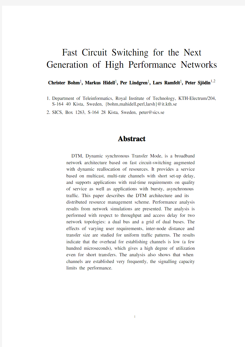
The service provided is based on channels . A channel is a set of time slots with a sender and an arbitrary number of receivers; it is guaranteed that the data will reach the receivers at the rate given by the capacity of the channel. The channels on the physically shared medium are realized by a time division multiplexing (TDM) scheme (Figure 1). The total capacity is divided into cycles of 125 microseconds which are further divided into 64-bit slots.
Figure 1. DTM multiplexing format The slots are separated into data and control slots. Each node has access to at least one control slot, which is used for sending control information to the other nodes.Control messages can be sent upon request from a user, in response to control messag-es from other nodes or spontaneously for management purposes. The control slots con-stitute a small fraction of the total capacity, while the major part of the slots are data slots carrying payload. At system start-up, the data slots are allocated to the nodes ac-cording to some prede?ned distribution. This means that each node “owns” a portion of data slots. A node needs ownership of a slot to send data in it, and the ownership of slots may change dynamically among the nodes during the operation of the network.
2.1 Slot Allocation
DTM uses a distributed algorithm for slot reallocation, where the pool of free slots is distributed among the nodes. There were two main reasons for using a distributed scheme instead of a central pool of slots. First, when a node can establish a channel us-ing only slots from the local pool, there is very little overhead in the channel establish-ment. Second, a distributed algorithm does not rely on a single node, so it has some tolerance to node failures. The main drawback of a distributed implementation is the overhead of communication and synchronization between nodes.
At the reception of a user request, the node ?rst checks its local pool to see if it has slots enough to satisfy the request and, if so, immediately sends a channel establish-ment message to the next hop. Otherwise the node ?rst has to request more slots from the other nodes on the bus. Each node maintains a status table that contains informa-tion about free slots in other nodes, and when more slots are needed the node consults its status table to decide which node to ask for slots. Every node regularly sends out status messages with information about its local pool of slots. Status messages have lower priority than other control messages so they are only sent when the control slot otherwise would be unused. Furthermore, the reallocation algorithm does not depend on nodes to process all status messages, so a node can safely ignore status messages while it is busy.
Data slots
Control slots
125 μs cycles
64-bit slots
The procedure for slot reallocation is simple and works as follows: if a user requests a channel with M slots and the node has N free slots, where , it sends requests asking for slots. The node starts by sending a request to the closest node with free slots. If this node does not have suf?ciently many free slots, according to the sta-tus table, a request is sent also to the second closest node with free slots, and so on.The node waits until a response for each of the requests has been received and then grants or rejects the channel request, depending on the outcome of the reallocation procedure.
A node that has some amount J of free slots and receives a slot reallocation request for K slots will always give away min(J, K ) slots. The node responds by sending a slot reallocation con?rmation, which indicates what slots the node gives away. If the re-quested node does not have any free slots, it responds with a slot reallocation reject in-stead. In addition to this algorithm, resources may be controlled by a network management system. For example, to prevent the network from starvation, a node can be con?gured not to give away all its slots, but to keep a certain fraction of its initial share.
2.2 Switching
A DTM network can be expanded by interconnecting several buses with switch nodes (see Figure 2). DTM uses decentralized switching in the sense that any node connected to two or more buses can switch data between them. One advantage with this is that the switching capacity can be increased gradually by adding more switch nodes. The switching is synchronous, which means that the switching delay is constant for a channel. This means that a multi-hop channel has roughly the same properties as a channel on a single bus. The only difference is that a switched channel has slightly longer delay (up to 125 microseconds for each hop). Provided that a switch node can buffer one cycle of data for each of its buses, there cannot be any congestion or over-?ow in the node.
The synchronization between buses is done on a per cycle basis—cycles are started with the same frequency on all buses. This is accomplished by letting one network node be responsible for generating the cycles periodically on all its outgoing buses.For each new cycle, this node generates a cycle-start marker that is forwarded to all buses in the network. For each bus there is one switch node that is responsible for for-warding the marker onto the bus. Those switch nodes need to be organized in such a way that the marker reaches every bus exactly once. When the marker reaches a bus,
N M the cycle is restarted on this bus. The reader is referred to [12] for more details on the synchronization scheme. Figure 2. DTM nodes interconnected in a mesh structure The cycle time and the slot size are both constant for all buses, which means that the synchronization scheme allows different buses to run at different bit rates. This makes it possible to upgrade or recon?gure individual buses in a network without affecting the rest of the network. 2.3 DTM channels The channel abstraction in DTM differs from ordinary circuits, in that channels have the following properties. ?Simplex: a channel is set up from sender to receivers. A duplex connection con-sists of two channels, one in each direction. ?Multirate: channels may consist of an arbitrary number of data slots, which means that channel capacity can be any multiple of 512 Kbps, up to the entire data capacity of the bus. ?Multicast:a channel can have several receivers. A node creates a channel by allocating a set of data slots for the channel and by sending a channel establishment control message. The control message is addressed either to a single node or to a multicast group, and announces that the channel has been created and what slots it uses. To create a channel, slots must be allocated at the sender and at each switch node along the channel’s route. Thus, switch nodes allocate slots for a channel on behalf of the sender. The switch nodes then start switching the channel, by copying the chan-nel’s slots from the incoming to the outgoing bus. An attempt to establish a multi-hop channel fails if any of the switch nodes involved cannot allocate the required amount of slots. In this case another route has to be tried. In a grid structure, there are normally several routes between each pair of nodes. The current version of the protocol uses source routing [17] together with an addressing scheme based on (x, y ) coordinates in the grid. A simple load-balancing scheme for two hops is achieved by letting each switch node use status messages to send information about the amount of free slots on Node 2 Node 1bus B bus A Node 3Node 4 its outgoing buses. For example, there are two possible routes between node 1 and node 4 in Figure 2, so if node 1 wants to set up a connection to node 4 it can choose between using switch node 2 and switch node 3. Node 1 receives status information from node 2 and 3, and can make its routing decision based on this information. This algorithm works well for dense grid networks, where most routes use only two hops,but a general routing algorithm is required for more arbitrary topologies. 2.3.1 Multicast channels A traditional circuit is a point-to-point connection between a sender and a receiver.DTM uses a shared medium which inherently supports multicast since a slot can be read by several nodes on a bus. A multicast channel can easily be extended to span over several hops, since the switch operation is actually a multicast operation, in the sense that it duplicates data onto another bus (see Figure 3). Figure 3. A multicast group 3 Network Performance In this section we investigate throughput and delay under varying traf?c conditions.We have performed simulations for two different network topologies : ? A dual bus with 100 nodes. ? A fully connected grid of dual buses with 20×20 nodes. In the simulation model, nodes receive transfer requests from a traf?c generator and control messages from other network nodes. These events are put in an input queue at the node, and the node processes one event at a time. The time to process one event is 5 microseconds. Transfer requests are generated by Poisson processes, and source and destination addresses are uniformly distributed. For each transfer request, a node at-tempts to allocate slots and, if that succeeds, establishes the channel, transfers the data and takes down the channel. This means that slots are released as soon as the transfer is done. Sender Switching node Switching node Receiver Receiver Receiver Receiver Receiver The simulations are performed for different transfer sizes (1 to 256 kilobytes), for different kinds of user requirements, and for different inter-node distances (0.01 to 10 kilometers). The link bit-rate is 4.8 Gbps, which gives a slot rate of 75 MHz and a cy-cle size of 9600 slots. Each transfer requests 40 slots per cycle. This corresponds to 20.48 Mbps channels, which means that a 16 kilobyte transfer, for example, takes about 6 milliseconds. We calculate the throughput by dividing the total amount of transferred user data by the simulated time, and normalize this value to the capacity of one dual bus (9.6 Gb-ps). The maximum throughput that is possible to achieve is always less than the link capacity, since some capacity is used for control messages. In the single dual bus sim-ulations, with 100 nodes, the control capacity is 5 control slots per node, which corre-sponds to 5% overhead. The maximum possible throughput is then 0.95. The grid has more nodes than the single dual bus, but fewer nodes per bus (20 in-stead of 100). Since the traf?c load on a bus is distributed over its nodes, this means that at a given bus load, the grid will have more traf?c to and from each node. A node in the grid therefore needs more control slots. However, a node has limited capacity to process control messages, and we have found that with 5 microseconds event process-ing time, very little performance is gained by using more than 10 control slots per node. We therefore use 10 control slots per node in the grid, which gives a maximum possible throughput of 0.98. Access delay is the average time from the time that a request arrives to the node un-til the data transfer starts. It is a measure of the overhead at channel establishment and includes the time it takes to allocate slots, send a channel establishment message to the receiver, and send the ?rst slot of data. In the multi-hop case, the sender waits for a con?rmation from the receiver that the channel has been established on both buses be-fore it starts sending data. For the single hop case, the sender alone creates the channel to the receiver, and can therefore start sending data as soon as the slots have been allo-cated. 3.1 One Dual Bus The ?rst set of simulations concerns performance of one dual bus. The purpose of these simulations is mainly to study slot allocation schemes for different user require-ments. Since slot allocations on different buses are independent operations, these re-sults are generally applicable for the multi-hop cases as well. 3.1.1 Strict Capacity Demand Without Retry Figure 4 shows the results of a basic simulation where a node makes at most one at-tempt to allocate the requested capacity for a channel, and rejects the request if the full requested capacity cannot be allocated. Transfer sizes between 1 and 256 kilobytes are simulated. The simulations could not be carried out for the smallest transfers (1 and 2 kilobyte in Figure 4) at high load, due to the simulator event queue growing too large, indicating that the control capacity is exhausted. Figure 4. Throughput and access delay for different packet sizes. At low load, most transfer requests are accepted immediately and the throughput therefore increases linearly with the load. At higher load, slot reallocation becomes frequent, some transfer requests are rejected, and the throughput increases only mar-ginally with the load. If the load gets even higher, the signalling capacity is exhausted,and throughput does not increase (or goes down, as in the case for 1 kilobyte transfers in Figure 4). Smaller transfers require more frequent control signalling than large transfers at a given load, and therefore throughput is lower for smaller transfers than for larger (at most 0.47 is achieved for 1 kilobyte transfers, which is 50% of the maxi-mum possible throughput, compared to 85% for 256 kilobyte transfers). Throughput is also limited by the strict user behaviour, requiring the entire requested capacity to be allocated in a single attempt. The simulations reported below show that throughput can be increased by relaxing this requirement. The access delay consists, at low load, mainly of the time it takes for a node to proc-ess the transfer request, wait for the ?rst available control slot (for the channel estab-lishment message), and then for the ?rst data slot (80 microseconds together, on the average). When the load increases, nodes have to request slots from other nodes and more delay is introduced. 3.1.2 Strict Capacity Demand with Retry It is possible to increase throughput by letting a node retry , that is, make more than one attempt to allocate slots for a channel. Figure 5 shows throughput and access delay for different values of the maximum number of retries allowed. When nodes are al-lowed to retry, more channels can be established and throughput increases (up to 92%of the maximum possible throughput), but at the expense of longer access delay and more signalling. Thus, retry is best suited for applications that have strict bandwidth demand but can tolerate some access delay. However, if a large number of requests are persistently retried (as in an overload situation), performance will degrade. Figure 5 00.2 0.40.60.8 1 00.20.40.60.81 1.2 1.4T h r o u g h p u t Offered load 256 kB 64 kB 16 kB 4 kB 2 kB 1 kB 050100 150 20025030035040045050000.20.40.60.81 1.2 1.4 D e l a y (m i c r o s e c o n d s )Offered load 256 kB 64 kB 16 kB 4 kB 2 kB 1 kB shows that performance decreases when the load is high and nodes are allowed to retry 20 times, which indicates that the signalling capacity is not suf?cient for 20 retries. Figure 5. Throughput and delay for strict capacity demand with retry (16 kilobyte transfers) 3.1.3 Flexible Capacity Demand An application with less stringent demands on capacity may be prepared to accept channels with less capacity than requested. This allows more channels to be estab-lished with a single slot reallocation attempt. Figure 6 shows throughput and delay for three cases: when the user is satis?ed with any capacity (minimum 1 slot), requires at least half the requested capacity (20 slots), and needs the full capacity (40 slots).Throughput goes up when the user is less demanding. When the user requires only one slot, the throughput achieved is 94% of the maximum possible throughput. The slot re-allocation procedure is however the same in all three cases, which explains why access delay is practically the same in the three cases. Figure 6. Throughput and access delay for different user requirements (16 kilobyte transfers). 3.1.4 Performance as a Function of Distance When the distance between nodes is increased, it takes longer time to exchange con-trol messages for slot reallocation. This can be seen in Figure 7, which shows through-put and access delay for different bus lengths (with strict capacity demand without retry, i.e., the same slot allocation principle as in Figure 4). The access delay increases signi?cantly when the bus gets longer. However, this affects mainly the creation of 00.20.40.6 0.81 00.20.40.60.81 1.2 1.4T h r o u g h p u t Offered load no retry 1 retry 2 retries 5 retries 10 retries 20 retries 0200 400 600800100000.20.40.60.81 1.2 1.4D e l a y (m i c r o s e c o n d s )Offered load no retry 1 retry 2 retries 5 retries 10 retries 20 retries 00.2 0.40.60.8 1 00.20.40.60.81 1.2 1.4T h r o u g h p u t Offered load 1 slot 20 slots 40 slots 050100 150 20025030035040045050000.20.40.60.81 1.2 1.4D e l a y (m i c r o s e c o n d s )Offered load 1 slot 20 slots 40 slots channels, and throughput is therefore relatively independent of distance. Another ef-fect of increased bus length is that it takes longer time to propagate status information,which may increase the probability of slot reallocation failure. This would mainly in-?uence throughput, but the simulation results indicate that this has only a minor effect. Figure 7. Network throughput and access delay as a function of bus length (16 kilobyte transfers). 3.2 Grid Network Figure 8 shows the result of a simulation for multi-hop channels. The network is a fully connected grid network with 20× 20 nodes. Channels use at most two hops, and the routing decision is based on the information from status messages. The slot alloca-tion principle is the same as in Figure 4, that is, strict demand without retry. Figure 8. Throughput and access delay in a 20× 20 grid. With uniform distribution of source-destination pairs, the theoretical maximum throughput of a fully connected grid is , where n is the number of buses. With 2.1% signalling overhead, the 20× 20 grid has a maximum possible throughput of ap-proximately 20.6. Figure 8 shows that for 256 kilobyte transfers, the maximum throughput is 97.5% of the possible maximum, compared to 95.1% for 16 kilobyte transfers. This is signi?cantly more than in the case of one dual bus (Figure 4), and our explanation for this is that there are less nodes per bus in the grid, which means that the pool of free slots is less scattered, and therefore there is a higher probability that slot reallocation succeeds. 00.2 0.40.60.8 1 00.20.40.60.81 1.2 1.4T h r o u g h p u t Offered load 1 km 10 km 100 km 1000 km 050100 150 20025030035040045050000.20.40.60.81 1.2 1.4D e l a y (m i c r o s e c o n d s )Offered load 1 km 10 km 100 km 1000 km 050 100 150 200250300350400450500 0510********D e l a y (m i c r o s e c o n d s )Offered load 256 kB 64 kB 16 kB 05101520051015202530T h r o u g h p u t Offered load 256 kB 64 kB 16 kB n 2?1+ The access delay for a multi-hop channel will be longer than on a single hop, since slots have to be allocated on two buses. For 256 kilobyte transfers, the access delay is roughly 50 per cent longer in the multi-hop case compared to the single hop case. One could expect the access delay in the grid to be longer than this. There are two main reasons why this is not the case. First, there is a certain amount of parallelism in chan-nel establishment over two hops. Second, the interval between control slots is shorter in the grid, so a node spends less time waiting for control slots. For 16 kilobyte trans-fers, however, the delay increases dramatically for higher load, which indicates that signalling capacity is insuf?cient. 4 Conclusion and Future Work The Dynamic synchronous Transfer Mode (DTM) is a network architecture for inte-grated services. It is based on fast circuit switching, and provides multi-rate, multicast channels with short set-up time. A channel gives guaranteed capacity and constant de-lay, which makes it well suited for real-time traf?c, such as video and audio. In con-trast to traditional circuit-switched networks, DTM also provides dynamic reallocation of resources between nodes in order to support dynamically varying traf?c. We have reported performance analysis through computer simulations for various con?gurations. The analysis focuses on packet-like traf?c patterns, since this type of traf?c is considered to be the most challenging for a network based on circuit switch-ing. The intention is to study how network utilization and access delay are affected when channels are frequently established and released. We use 20 Mbps channels, where a channel is established for each transfer, and the transfer size varies between 1 and 256 kilobytes. The analysis was performed for two kinds of topologies: a dual bus and a grid of dual buses. The protocol requires that a certain fraction of the total capac-ity is reserved for control information: we used about ?ve per cent for the dual bus, and two per cent for the grid. The results show that when the traf?c consists of short, frequent transfers (of a few kilobytes), performance is determined by the amount of signalling capacity available. For the dual bus, good results are achieved even when the network is loaded with transfers that are only few kilobytes long, whereas the grid was saturated for 16 kilo-byte transfers. To summarize, the paper shows that fast circuit switching, as applied in DTM, performs well even for packet traf?c using short-lived connections. This, in combination with its inherent support for real-time traf?c, makes fast circuit-switching an appealing alternative for B-ISDN and beyond. For future work, the performance results suggest that in order to send packets on DTM, one needs to ?nd a scheme for multiplexing packets onto channels that groups packets together into slightly larger units. Assuming that computers generate traf?c that conforms to the train model [18]—bursts of packets where many of the packets within a burst have the same destination—a simple scheme similar to those used in the early fast circuit-switched networks seems appropriate [13], [15]. In such a scheme, the channel is closed and its resources are released when the sender has been idle for more than a certain period. This is, however, an area that needs further investigation. The performance results are encouraging and we will explore further the effects of non-uniform traf?c models, such as bursty sources and asymmetric sender-receiver distributions. In addition, we will implement and investigate mechanisms such as fast channel creation [19], [20], [21] and slot reuse [22] in the simulator. References [1]P. O’Reilly, “The case for circuit switching in future wide bandwidth net- works”, In Proc. of IEEE ICC, Philadelphia, Pennsylvania, June 1988, pp. 899-904. [2]R. H?ndel and M. N. Huber, “Integrated Broadband Networks”, Addison-Wes- ley, 1991. [3]J. S. Turner, “New Directions in Communications (or Which Way to the Infor- mation Age?)”, IEEE Communications Magazine, V ol. 24, No. 10, pp. 8-15, Oct. 1986. [4]?. M. Aras, J. F. Kurose, D. S. Reeves and H. Schulzrinne, “Real-Time Com- munication in Packet-Switched Networks”, Proceedings of the IEEE, V ol. 82, No. 1, pp. 122-139, Jan. 1994. [5]T. M. Chen and S. S. Liu, “Management and Control Functions in ATM Switching Systems”, IEEE Network Magazine, V ol. 8, No. 4, pp. 27-40, July/ Aug. 1994. [6]M. Decina, “Open issues regarding the universal application of ATM for multi- plexing and switching in the B-ISDN”, In Proc. of IEEE ICC, Denver, Colo- rado, June 1991, pp. 1258-1264. [7]J. Gechter and P. O’Reilly, “Conceptual Issues for ATM”, IEEE Network Mag- azine, V ol. 3, No. 1, pp. 14-16, Jan. 1989. [8] B. G. Kim and P. Wang, “ATM network: goals and challenges”, Communica- tions of the ACM, V ol. 38, No. 2, pp. 39-44, Feb. 1995. [9]L. Kleinrock, “The Latency/Bandwidth Tradeoff in Gigabit Networks”, IEEE Communications Magazine, V ol. 30, No. 4, pp. 36-40, April 1992. [10]C-T. Lea, “What Should Be the Goal for ATM”, IEEE Network Magazine, V ol. 6, No. 5, pp. 60-66, Sept. 1992. [11]R. J. Vetter, “ATM concepts, architectures, and protocols,”, Communications of the ACM, V ol. 38, No. 2, pp. 28-38, Feb. 1995. [12] C. Bohm, P. Lindgren, L. Ramfelt and P. Sj?din, “The DTM Gigabit Network”, Journal of High Speed Networks, V ol. 3, No. 2, pp. 109-126, 1994. [13]R. L. Easton, P. T. Hutchison, R. W. Kolor, R. C. Mondello and R. W. Muise, “TASI-E Communications System”, IEEE Transactions on Communications, V ol. 30, No. 4, pp. 803-807, April 1982. [14] E. A. Harrington, “V oice/Data Integration Using Circuit Switched Networks”, IEEE Transactions on Communications, V ol. 28, No. 6, pp. 781-793, June 1980. [15]S. D. Personick and W. O. Fleckenstein, “Communications Switching — From Operators to Photonics”, pp. 1380-1403, Proceedings of the IEEE, V ol. 75, No. 10, Oct. 1987. [16]S. R. Amstutz, “Burst Switching — An Update”, IEEE Communications Mag- azine, V ol. 27, No. 9, pp. 50-57, Sept. 1989. [17] C. A. Sunshine, “Source Routing in Computer Networks”, ACM Computer Communication Review, V ol. 7, No. 1, pp. 29-33, Jan. 1977. [18]R. Jain, S. A. Routhier, “Packet Trains—Measurements and a New Model for Computer Network Traf?c”, IEEE Journal on Selected Areas in Communica-tions, V ol. 4, No. 6, pp. 986- 995, Feb. 1986. [19]P. E. Boyer and D. P. Tranchier, “A reservation principle with applications to the ATM traf?c control”, Computer Networks and ISDN Systems, V ol. 24, No. 4, pp. 321-334, May 1992. [20]P. Lindgren and C. Bohm, “Fast Connection Establishment in the DTM Gigabit Network”, In Proc. 5th IFIP Conference on High Performance Networks, Grenoble, France, June 27-July 1, 1994, pp. 283-294. [21]L. Roberts, T. MacDonald and G. Bernstein, “Fast Select Virtual Circuit Rout- ing for B-ISDN Networks”, In Proc. of ISS’92, Yokohama, Japan, Oct. 1992, pp. 219-228. [22]M. W. Garret and S-Q. Li, “A Study of Slot Reuse in Dual Bus Multiple Access Networks”, IEEE Journal on Selected Areas in Communications, V ol. 9, No. 2, pp. 248-256, Feb. 1991. Christer Bohm was born in S?dert?lje, Sweden in 1966. He received his M.Sc. de-gree in electrical engineering in 1990 and his Technical Licentiate degree in telecom-munication in 1994 from the Royal Institute of Technology, Stockholm. His main research areas are high performance networks, network simulations and protocol im-plementations. He is a Ph.D. student and a Research Staff member at the department of Teleinformatics and is currently working in a joint project with Ericsson to further de-velop the DTM network architecture. Markus Hidell was born in Stockholm, Sweden in 1967. He received his M.Sc. de-gree in electrical engineering in 1992 and is currently working towards a Ph.D. in tele-communication at the Royal Institute of Technology, Stockholm. His main research areas are high performance networks, host interfacing and protocol implementation. He is a Research Staff member at the department of Teleinformatics and is currently working with the design and implementation of the DTM network architecture. Per Lindgren was born in Stockholm, Sweden in 1967. He received his M.Sc. de-gree in electrical engineering in 1990 and his Licentiate degree in telecommunication in 1994 from the Royal Institute of Technology, Stockholm. His main research areas are high capacity networks, host interfacing and multi channel systems. He is currently designing and implementing an enhanced DTM network architecture using parallel bitstreams. Lars Ramfelt received his M.Sc. degree in electrical engineering from the Royal In-stitute of technology 1990. He is working towards the Ph.D. degree in Telecommuni-cations at Department of Teleinformatics. During 1993-1994 he was in the Optical De?ection Network group, University of Colorado in Boulder. His main research areas are high speed optical networks, switch design, and network simulations. Currently he is working on enhanced versions of the DTM protocol supporting slot reuse. Peter Sj?din received the M.Sc. and Ph.D. degrees in computer science from Uppsa-la University in 1982 and 1992, respectively. He has been with the Swedish Institute of Computer Science since 1986 as a researcher in the Computer and Network Architec-tures group. Since 1993, he is a Faculty Member in the Department of Teleinformatics at the Royal Institute of Technology, Stockholm. His current research interests are in protocols for high-speed networks and real-time multimedia systems. For... Next 循环语句For…next 循环简称为For 循环。它是一种指定循环次数(事先知道循环次数)的循环程序结构。在这种结构中,使用了一个称为循环变量的特殊变量作为计数器,指定它的初始数值,然后每重复执行一次循环,循环变量就会自动增加或减少一个指定的数值(称为步长值),直到循环变量的改变达到最终的指定值,循环才停止执行。1.For …Next 语句的语法格式 For <循环变量>=<初值> To <终值> [Step 步长] [语句块] [Exit For ]Next [循环变量] 功能:用来控制重复执行一组语句。指定循环变量以步长为增量,从初值到终值依次取值,并且对于循环变量的每一个值,把语句块执行一次。 说明:(1)关键字For 和Next 成对出现,For 是循环语句的开始,Next 是循环语句的终端,必须出现在For 语句的后面。在关键字For 和Next 之间的语句块叫循环体,它们将被重复执行指定的次数,执行的次数由初值、终值、步长值决定。(2)初值、终值和步长值都是数值表达式,步长值可以是正数,也可以为负数。如果步长值为1,可以省略不写,即系统默认步长值为1。 (3)<循环变量>为必要参数,是用作循环计数器的数值变量,这个变量不能是数组元素。在循环体内,一般不提倡再给循环变量另外赋值。循环变量从初值开始,逐次按照步长值增加或减少而改变,直到超过终值,这时循环停止执行。这里所说的“超过”有两种含义:即大于或者小于。 (4)<初值>和<终值>也都是必要参数。当初值小于终值时,<步长值>必须是正数;反过来,如果初值大于终值,则步长值必须为负数。(5)如果循环体中安排了Exit For 语句,当程序执行到该语句时直接跳出循环结构,不再执行循环体中Exit For 的后续语句(如果有),而是转到Next 后面的其他指令 继续执行。 (6)Next 语句中的[<循环变量>]可以省略。 2. For... Next 语句的执行过程:进入For...Next 循环后,程序按照以下步骤执行:(1)若初值、终值和步长值为表达式,求出它们的值,并保存起来:资料试卷布置情况与有关高中资料试卷电气系统接线等情况,然后根据规范与规程规定,制定设备调试高中资料试卷方案。 信息技术 - FOR/NEXT循环语句教学设计_高中信息技术2009-10-24 18:33:09来源: 作者:佚名【大中小】浏览:43607次评论:1条 ■以下为本文简介:------------一、课前分析教学内容:FOR/NEXT循环语句。 1、教材分析 1)教学内容和地位:程序设计是教学中的重点也是难点,循环结构是其中的一种设计结构,其作用是...... 以下为本文简介:------------ 一、课前分析 教学内容:FOR/NEXT循环语句。 1、教材分析 1)教学内容和地位:程序设计是教学中的重点也是难点,循环结构是其中的一种设计结构,其作用是使一段程序反复执行。FOR/NEXT语句是循环运算的专家,在程序设计中频繁出现。本节课的学习,会使学生对算法有一个更深刻的理解,为实现独立编程起到了关键性作用。 2)教学重点与难点:本节课重点是掌握FOR/NEXT循环语句的格式,并能运用其来编制简单的小程序。难点是解决问题的方法和思路,要绘制好流程图,确定循环变量和循环体。因为用流程图描述算法,能够把解决问题的步骤清晰、直观地表示出来。 2、教学目标分析: 1)认知目标:通过FOR/NEXT语句的学习,写出简单的循环程序。 2)能力目标:培养学生分析问题,解决问题的能力。 3)情感目标:激发学生学习热情,培养学生学习的积极性。 二、教学过程 1、创设问题情境 师:同学们,请先看这个图形(画5个竖行排列的“*”),想想看用以前学过的程序设计语言怎样来编写它的程序呢?(本节程序均设置为单击命令按钮cmdstart运行即代码加在private sub cmdstart_click()) 生(稍做思考,然后回答):使用PRINT语句 PRINT “*” PRINT “*” PRINT “*” PRINT “*” PRINT “*” 师:同学们做得很好,那么,我想画10行,100行,1000行“*”呢?难道就这样顺序写下去吗?这样编写是不是太繁琐了。如果能让计算机去完成这部分重复的内容,而我们只要告诉计算机重复操作的次数就可以了,这个愿望能否实现呢?能!通过我们今天学习的FOR/NEXT循环语句,就可以很容易的实现这个愿望。 [疑问是建构教学的起点。新课伊始,就提出一个真实的问题,力求创设一种教学情境,它可以激起学生的未知欲,有利于建立新的认识结构。] 2、给出程序,并通过流程图加以理解 师出示上题程序代码并通过流程图和卡通图片分析 教学设计 题目:For-Next循环培训院校:新疆教育学院数信分院专业班级:1132初中信息技术班学号: 1132102118 姓名:胡安太 13.For-Next循环 标题:For-Next循环 课时:第一课时 年级:初三 教学重点,难点:使用FOR-Next语句实现循环结构的方法,循环变量。一.教学目标 1.知识目标 (1)循环体,循环控制变量(变量),了解循环的概念、理解循环结构的基本思 想 (2)把握for…next语句的基本结构(循环嵌套,内循环,外循环) (3)理解for…next语句的执行过程;(实现循环结构的方法) 2.素质目标 (1)学生学习循环过程中能够培养学生的思考能力 (2)学习过程中可以充分发挥学生的逻辑能力。 3.情感目标 (1)养成学生独立思考的良好习惯 (2)提高学生面对现实,敢于面对失败的意识,加强他人的忍耐性。 (3)通过一个个任务的实战演练,感知使用循环结构解决问题的便捷和优越,培养学生运用循环思想解决实际问题的能力,进一步激发学生学习编程的爱好。 (4) 通过在实际的问题中分析提炼循环结构,从程序设计领域进一步提升学生 的信息素养 二.教学过程 1.(1)复习程序的顺序结构 前面我们讲过程序的顺序结构,计算机最基本的结构。 师:谁能回答,什么是顺序结果? 学生:回答上述的问题。如果能回的老师表扬,没有人回答,有老师来复述。 (2)复习程序的分支结构 师:有时候处理问题时,比如判断一个年份是否闰年,需要根据某个条件进行判断。 1.什么是分支结构? 2.我们所学的那个语句是分支结构的? 3.谁能写下来它的格式? 学生:让几个学生回答这个问题。如果答对了表扬,答错了,那就老师引导学生回顾那些内容。下面是回顾内容: For—Next循环语句(第一课时) 一、学习者分析 在此之前,学生已经学习了程序的基本要素、顺序结构、分支结构,对程序结构有了一定的了解和掌握,知道顺序结构和分支结构的区别,同时在学习上也出现了分化。为了不让学生的分化加剧,增加学生的畏难情绪,安排了两个课时进行循序渐进的教学、增加学生的学习兴趣,减弱畏难情绪。 二、教材内容分析 (一)、本节的主要内容及在本章中的地位 本节是广州市信息技术教科书初中第二册第二章第六节循环结构中的For—Next 循环语句。是程序设计初步的重点、难点。由于循环结构相对顺序结构和分支结构比较抽象和不易理解,因此在教学中宜自然地引入For—Next循环语句的功能、格式。 (二)、教学重点、难点 重点:For—Next循环语句的格式和作用。 难点:For—Next循环语句的执行过程和应用。 (三)、课时安排:2课时(本节为第一课时)。 三、教学目标 (一)知识与技能 1、掌握For-Next循环语句的格式。 2、了解For-Next循环语句的作用,理解画同心圆程序的执行过程。 3、理解改变循环变量的值控制循环次数的意义。 4、根据实际情况,能够应用For-Next循环语句修改及编写程序。 (二)过程与方法 1、通过观看例子,模仿、修改、编写程序,掌握For-Next循环语句的格式和特点。 2、通过观察、分析画同心圆的程序,逐步掌握For-Next循环语句的执行过程和应用。 3、通过体验探究、思考、讨论等形式,了解For-Next循环语句程序设计在解决问题过程中的方法和作用,学会利用For-Next循环语句处理已知重复次数的循环问题。 (三)情感态度与价值观 1、学生通过教师的情景设置以及对程序的体验修改,克服学习过程中的畏难情绪,在不断的探究和思考中培养探索精神,能够真正体验成功的喜悦。 2、学生通过分层次的任务设计,提升学习兴趣、求知欲、对程序设计的兴趣,养成认真、严谨的学习态度和良好的心理素养。 四、教学理念和方法 本节课教师主要采用的方法包括:体验法、指导法以及任务驱动。体验法是以教师为主导,学生主动探究、亲身体验、思考总结提高,在学习过程中体验学习的乐趣和方法。指导法可以在学生操作过程中观察学生的实际掌握情况,发现存在的问题并及时加以指正。任务驱动可以激发和保持学生的学习兴趣,尽可能多地提供学生动手实践的机会。通过教师的情景设置,不断提高学习任务的梯度,使学生逐步掌握知识,培养学生的实践和创新能力。 五、教学资源 深蓝易思多媒体教学系统、学生使用的主题网站(包含课堂评价系统)、教师使用的主题网站(包含powerpoint课件和课堂评价的统计系统)、教科书、计算机、投影等。 《For…next循环结构》教学设计(修改稿) 海口市第一中学王锡君 2007年全国高中信息技术课展评二等奖作品 一、教材分析: 《for…next循环》选至高中选修教材《算法与程序设计》(教科社版)2.3.3节《循环结构》。教材中《循环结构》主要包含《for…next循环》和《do while…loop循环》等两部分内容,各用一课时,共计两课时。本设计为第1课时。 循环结构是最为常用的语法结构之一,也是三大基本结构中难度最大的一个;不仅是本章的重点与难点,也是全书的重点之一。学好程序的基本结构,是学生理解和学习后续章节的基础。 二、学情分析: 在学习本课之前,学生本应已熟悉VB程序的编程环境与运行方法,了解顺序及选择结构的程序执行流程,具备一定的算法基础和归纳总结能力。 但根据安排,授课对象为天津实验中学高一学生,绝大多数学生并接触过程序设计和VB环境,动手能力较差。并且《算法与程序设计》≠某一编程工具(语言)的教学。故本课有意弱化学生在纯VB环境中的代码编写,而重在理解循环结构的基本思想,学会怎样分析循环问题、设计算法,并提炼for语句的基本结构,旨在培养学生根据需要采用循环结构解决实际问题的能力,故任务设置以完善半成品居多。 三、教学目标: 1. 知识与技能: 1) 了解循环的概念、理解循环结构的基本思想; 2) 掌握for…next语句的基本结构; 3) 理解for…next语句的执行过程; 4) 尝试采用循环结构编写简单的程序,解决实际问题。 2. 过程与方法: 经历分析、实践、讲解、探究、归纳,通过循序渐进、层层深入,逐步深化对循环思想和执行过程的理解。3. 情感、态度与价值观: 1) 通过一个个任务的实战演练,感知使用循环结构解决问题的便捷和优越,培养学生运用循环思想解决实际问题的能力,进一步激发学生学习编程的兴趣。 2) 通过在实际的问题中分析提炼循环结构,从程序设计领域进一步提升学生的信息素养。 四、教学重点、难点: 1) 教学重点:①掌握for…next语句的基本结构;②理解for…next语句的执行过程 2) 教学难点:根据需要采用循环结构解决实际问题,并提炼出for语句的基本结构。 五、教学方法:讲授演示法、对比分析法、任务驱动法、分层教学法等。 六、教学过程: (一)创设情景、激情导入 课题编制计算机程序解决问题 --For/Next循环语句 课时一课时 课型新授授课人韦开静授课时间2012.3.12 授课班级高一(7)学科信息技术 教材分析 循环结构是程序设计的三种基本结构之一,是程序设计的基础;它的主要应用方向是让计算机重复做大量相同或相似的事情。教材只是通过SIN函数引出了For/Next循环语句,并没有给出它的语法格式,及其语句的具体执行过程。我认为这样会导致一些学生进行简单模仿,而不是真正的掌握和理解。学生只有熟练掌握了For/Next循环语句的格式,理解循环执行过程,才能在实际应用中游刃有余。所以,本节课我们将学习For/Next循环语句。 学情分析 教学对象为高一的学生,对程序的接触不太多,前面的课程只讲了程序中的基本元素,初步了解了流程图的画法,但没有通过实际的编程来上机实践。所以,本节课从简单的实例着手,让学生搞清楚什么情况下要去使用循环结构,怎么样来使用它。 教学目标1、知识技能目标: ①掌握For/Next循环语句的格式 ②理解For/Next循环语句的功能和执行步骤 2、过程方法目标: ①能够分析简单的For/Next循环语句功能,尝试编写简单的For/Next 循环程序 ②培养学生分析问题,解决问题的能力。 3、情感态度目标: 感受用计算机程序解决问题的魅力,激发学生学习程序设计的兴趣。 重点掌握For/Next循环语句的格式与执行步骤 难点运用For/Next循环语句编制简单的计算机程序解决实际问题 教学方式讲授法、任务驱动法、小组协作 教学准备多媒体网络教室、PPT 教学过程 教学环节教师活动学生活动设计意图 复习编制计算机程序解决问题的基本过 程:分析问题→算法设计→编写程序 →调试运行→检测结果 回答问题 唤起学生记忆,为 新课做铺垫 For... Next循环语句 For…next循环简称为For循环。它是一种指定循环次数(事先知道循环次数)的循环程序结构。在这种结构中,使用了一个称为循环变量的特殊变量作为计数器,指定它的初始数值,然后每重复执行一次循环,循环变量就会自动增加或减少一个指定的数值(称为步长值),直到循环变量的改变达到最终的指定值,循环才停止执行。 1.For …Next语句的语法格式 For <循环变量>=<初值> To <终值> [Step步长] [语句块] [Exit For] Next [循环变量] 功能:用来控制重复执行一组语句。指定循环变量以步长为增量,从初值到终值依次取值,并且对于循环变量的每一个值,把语句块执行一次。 说明: (1)关键字For和Next成对出现,For是循环语句的开始,Next是循环语句的终端,必须出现在For语句的后面。在关键字For和Next之间的语句块叫循环体,它们将被重复执行指定的次数,执行的次数由初值、终值、步长值决定。 (2)初值、终值和步长值都是数值表达式,步长值可以是正数,也可以为负数。如果步长值为1,可以省略不写,即系统默认步长值为1。 (3)<循环变量>为必要参数,是用作循环计数器的数值变量,这个变量不能是数组元素。在循环体内,一般不提倡再给循环变量另外赋值。循环变量从初值开始,逐次按照步长值增加或减少而改变,直到超过终值,这时循环停止执行。这里所说的“超过”有两种含义:即大于或者小于。 (4)<初值>和<终值>也都是必要参数。当初值小于终值时,<步长值>必须是正数;反过来,如果初值大于终值,则步长值必须为负数。 (5)如果循环体中安排了Exit For 语句,当程序执行到该语句时直接跳出循环结构,不再执行循环体中Exit For的后续语句(如果有),而是转到Next后面的其他指令继续执行。 (6)Next语句中的[<循环变量>]可以省略。 2. For... Next语句的执行过程: 进入For...Next循环后,程序按照以下步骤执行: (1)若初值、终值和步长值为表达式,求出它们的值,并保存起来: For/next语句 一、教材分析 For/next语句是《算法与程序设计》中一个重点,也是后面学习面向对象程序设计的一个基础,如何有效教学,跨越这个门槛是我头痛之处,经了解,学生在数学上学习过循环结构,于是,通过整合数学资源实现突破。 二、学情分析 本节课教学对象是高二学生,通过一段时间的学习,学生已经具备了一定的抽象逻辑思维能力,并处于不断发展的阶段;积累了用计算机编程解决现实中的问题的初步经验。在此基础上学习for/next语句,再加上我校学生基础好,学习态度端正,习惯好。学好本节课内容不算什么难事。 三、教学目标 1、知识与技能: (1)、掌握For/Next语句的格式,理解For/Next循环语句的功能和执行步骤 (2)、能够分析简单的For/Next循环语句功能,尝试编写简单的For/Next 循环程序 2、过程与方法 首先,通过绘制同心圆的问题,让学生发现绘制不同半径的同心圆,反复使用circle函数所带来的麻烦,从而引出for/next语句,进而解决代码重复所带来的麻烦。让学生感到欣喜的同时,渴望知识。其次,通过任务设置进一步掌握for/next语句的使用方法,为学习双层循环做准备。最后,通过打印九九乘法表达到掌握双重循环的目的。 3、情感价值观 通过信息技术对其他学科的整合,提高学生学习算法的兴趣,激发学生编程的热情,同时也培养了学生的细心和耐心,加深了对计算机这一工具的认识,也增强了用计算机编程来解决一些无法用人工来计算的问题的信心。 四、教学重点与难点 For/next语句的使用方法和功能以及执行步骤。 根据实际情况,确定for/next语句的循环变量条件和循环体。 五、教学策略 本节课首先采用问题探究方法,引导学生发现问题,进而引出for/next语句;其次通过讲授for语句的使用方法和功能,增强学生对for语句的理解;最后通过实践任务的设置来巩固所学,达到学以致用的效果。 六、教学环境 多媒体机房 七、教学过程 For-Next循环语句--(第1课时) 【适用教材】广东教育出版社《信息技术》册 【适用年级】初二年级 一、教学内容分析 本节课讲授的是For-Next循环语句,因为之前学生学习过顺序结构,分支结构中的条件语句,对编程有了一定的基础,但是循环语句相对于条件语句来说,语法和语句的工作流程都复杂了,所以在讲述For-Next循环语句时,可以让学生分析程序的具体执行过程,引导学生分析For-Next 循环语句是如何实现程序的循环功能的,加深学生对循环功能的实现方法的理解。 二、教学对象分析 本节课的教学对象是初二学生,因为初二学生的理解能力有限,而这节课涉及的循环语句比较抽象,较难理解,因此在教学中宜比较自然地引入循环语句的功能、格式以及使用方法。并且为了学生更好地理解For-Next语句,尽可能使用程序与流程图结合的方法进行讲解。 三、教学目标 .初步理解循环结构的定义和作用; .初步掌握循环语句的一般格式; .结合For-Next循环语句的执行流程图理解循环结构 程序的执行过程。 四、教学重点以及教学难点 理解及初步掌握For-Next循环语句。 五、教学过程设计 复习程序的顺序结构 前面我们讲过程序的顺序结构,计算机最基本的结构。计算机在执行程序时,按照从上往下的顺序依次执行语句,这样的结构称为顺序结构。 复习程序的分支结构 有时候处理问题时,比如判断一个年份是否闰年,需要根据某个条件进行判断,然后再决定程序的执行过程,这种程序结构称为分支结构。前面我们所学过的If-Then-Else 条件语句就可实现条件的判断。 格式:条件语句的执行过程: IfThen Else EndIf 讲述新 引入: 有时,在解决一些问题时,经常需要重复执行一些操作, 课题:程序的基本结构——循环结构之For-Next语句第课时课型:新授备课教师授课时间 教学目标 知识与技能 1、了解循环的概念,理解循环结构的基本思想 2、掌握For-Next语句的基本结构的写法循环变量,初值,终值和步长。 3、理解For-Next语句的执行过程 过程与方法 1.通过分析问题,能准确找出循环变量、确定循环结束条件。 2.能利用For-Next语句解决简单的问题。 情感态度与价值观 1.通过编写循环结构的程序,体会循环结构的执行过程。 2.通过利用循环思想解决问题,体会循环思想的重要性。 教学重点1、理解循环结构的基本思想 2、理解For-Next语句的执行过程 教学难点根据需要采用循环结构解决实际问题,并提炼出for语句的基本结构学生理解For-Next语句的执行过程 教学 准备 几个以For-Next语句组成的不同功能的程序 教学过程设计教学 内容师生教学活动设计 备注栏 (学生笔记栏) 一、设疑导入 同学们,请先看这个图形(在窗体左边输出显示 竖行排列的1,2,3,4,5),如果用以前学过的程 序设计语言怎样来编写它的程序呢? 生(稍做思考,然后回答):使用Print语句 P rint“1” Print“2” Print“3” Print“4” Print“5” 师:同学们做得很好,,如果想要显示1-10,或是1-100的数字呢?怎么做,难道就这样顺序写下去吗?这样编写是不是太繁琐了。如果能让计算机去完成这部分重复的内容,而我们只要告诉计算机重复操作的次数就可以了,这个愿望能否实现呢? 通过我们今天学习的FOR—NEXT循环语句,就可以很容易的实现这个想法。 用FOR-NEXT循环语句编程序解决下列问题: 1.打印200到300中的整数,要求每行8个数。 For i= 200 to 300 Print I; t=t+1 If t mod 8=0 then print Next i End 2.一个数列如下:0,1,1,2,4,7,…从第四项开始,后面一项总是它前面三项的和, 输出这个数列的前20项。 a=0:b=1:c=1 Print a,b,c, For i=4 to 20 d=a+b Print d, a=b b=c c=d Next i End 3.求3位数中所有能被5整除的数的和。 For i=100 to 999 step 5 If I mod 5=0 then s=s+i Next i Print “s=”s End 4.按下列形式输出两位数除以7的整数部分和余数部分。 10 1 3 11 1 4 12 1 5 13 1 6 14 2 0 15 2 1 ………… 99 14 1 For i=10 to 99 A=I mod 7 B=Int(I \ 7) Print a,b Next i end 5.把1到100自然数中的能被7整除的数累加到X中不能被7整除的数累加到Y中。 X=0 : y=0 For i=1 to 100 step 1 If I mod 7=0 then x=x+I else y=y+i Next i Print x , y 6.求5+10+15+……+300的值。 S=0 : t=1 For i=5 to 300 step 5 S=s+i Next i Print “s=”;s end 7. 一个五位数41□72能被8整除,求方框里的数(答案:0,2,4,6,8)。 For i=0 to 9 step 1 X=41*1000+i*100+72 If x mod 7=0 then Print i Next i End 8.打印9*1=9 9*2=18 9*3=27 9*4=39 …… 9*9=81一行乘法表 for i=1 to 9 print 9;”*”;I;”=”;9*I; next i print end 9. 利用循环语句(FOR...NEXT)找出三位数中所有水仙花数。(例如153是水仙花数因为:153=1*1*1+5*5*5+3*3*3)(答案:有四个数) 用for……next语句实现循环 于芳 一、教学目标 知识与技能 (1)掌握For-Next语句的格式和功能。 (2)理解Fox-Next语句的执行过程,学会使用Fox-Next句解决生活中实际问题。 (3)理解for……next语句与do……loop语句的异同。 过程和方法 (1)经历实践—探究—分析—归纳,理解循环过程,培养探究能力。 情感态度与价值观 (1)小组合作,培养学生的团队精神。 (2)运用循环结构解决生活中实际问题,激发学生对程序设计的学习兴趣。 二、教学内容分析: 本节是建立在学生已经学习了顺序结构和分支结构,以及循环结构do……loop语句的基础之上,而又为后续的数组学习作了铺垫。多数学生对程序设计兴趣不大,因为学生认为生活离程序设计过于遥远,而且程序设计要求学生的逻辑思维非常强,学生理解比较困难,所以本节课主要从以下几方面着手: 注重学习内容和学生特点相结合,注重能力训练与问题解决相联系,只有提出处于“最近发展区的”,“跳一跳”就能摘到的果子,才能激起学生摘取的兴趣,把复杂的问题进行分解,教师仅引领,通过反馈逐步提示教学内容,让学生在亲历情境、亲手操作、亲身体验中掌握知识,发展能力、领悟技术中的思想和方法。 三、教学重、难点 教学重点: (1)掌握For-Next语句的格式和功能,理解Fox-Next语句的执行过程,学会使用Fox-Next 句解决生活中实际问题。 教学难点: (1)理解For—Next循环的执行过程,提高学生运用Fox—Next语句解决生活中实际问题的能力。 (2)比较两种循环格式的区别,会使用不同的循环格式解决相应的问题。 三、教学过程 Excel VBA编程For…Next循环 For…next循环语句是计数型循环语句,用于以指定次数来重复执行一组语句,其语法为:For counter = start To end [Step step] [statements] [Exit For] [statements] Next [counter] For …Next循环语句的语法具有以下几个部分: ●counter 必要参数。用于循环计数器的数值变量。这个变量不能是Boolean或数组元素。 ●start 必要参数。counter的初值。 ●End 必要参数,counter的终值。 ●Step 可选参数。counter的步长。如果没有指定,则step的缺省值为1。 ●Statements 可选参数。放在For和Next之间的一条或多条语句,它们将被执行指定的次数。参数step可以是正数或负数。参数step值决定循环的执行情况,如下表7-2所示: 当所有循环中的语句都执行后,step的值会加到counter中。此时,循环中的语句可能会再次执行(基于循环开始执行时同样的测试),也可能是退出循环并从Next语句之后的语句继续执行。 在循环中改变counter的值,将会使程序代码的阅读和调试变得更加困难。 提示 下面通过使用For…Next语句创建一个字符串,其内容为由0到9的十个数字所组成的字符串,每个字符串之间用空格隔开。外层循环使用一个变量当作循环计数器,每循环一次,变量值减一,其代码如下: Dim Words, Chars, MyString For Words = 10 To 1 Step -1 ' 建立10 次循环。 For Chars = 0 To 9 ' 建立10 次循环。 MyString = MyString & Chars ' 将数字添加到字符串中。 Next Chars MyString = MyString & " " ' 添加一个空格。 Next Words 在For …Next循环使用过程中,应注意以下两点内容: ●循环中可以在任何位置放置任意个Exit For语句,随时退出循环。 ●可以将一个For…Next循环放置在另一个For…Next循环中,组成嵌套循环。不过在每个循环中 的counter要使用不同的变量名。 ●当退出循环后,循环变量的值保持退出时的值。 ●在循环体内对循环控制变量可多次引用,但不要对其赋值,否则会影响原来的循环控制规律。 第四节《计数循环——for…next循环结构》教学设计 一、教材分析 本课是海南、三环出版社三环出版社《信息技术》九年级上册第二章第四节《数循环——For…Next语句》的内容,学生已经学习了程序设计中的顺序结构和分支结构,,初步掌握了VB程序设计的基本方法。而for-next循环是循环语句中最简单、最常用的一种,本节课是本章的重点内容之一。 二、教学目标 1、知识目标:掌握for…next循环语句的格式,理解for…next循环语句的功能和执行过程。 2、技能目标:掌握发for…nextt语句的格式,能够读懂简单的for-next循环程序。 3、情感目标:培养学生对VB程序设计语言的学习兴趣,激发学生学习的主动性和探究性。 三、教学重点和难点 1、教学重点:for…next语句的基本格式,循环程序的执行过程。 2、教学难点:for…next 语句的执行过程。 四、教学方法 教学方法:任务驱动法、讲解演示法、练习法。 五、教学过程 1、创设情景、引入课题 用速龙多媒体控制平台展示―移动中的汽车‖作为课题的导入。引起学生的兴趣从而激发学生学习的热情。提出小车移动的设计方法及实现的步骤。 师:小车移动的方向? 生:从左向右移动。 师:小车是如何实现从左向右移动的呢?小车在左边位置如何表达?通过看课本解决这个问题。 生:小车是一幅图,它左边位置可以表达为―Image1.left‖,向右移就是Image1.left+1。 师、生共同分析问题 执行Image1.left=Image1.left+1语句的过程,意思就是取出Image1.left的值,把它加上1,然后把这个值赋值到Image1.left中,使得Image1从当前位置向右移动一个单位的距离,如果我们反复写这个语句代码,Image1就会慢慢向右边移动了。有没有更简单的做法达到这样的效果呢?那就是我们今天所要学习用到的VB的―循环语句‖。 师:我们今天来学习循环结构,for-next循环语句。 师:利用多媒体教学系统的广播功能讲解for –next循环语句的格式 格式:For 循环变量=初值To 终值Step 步长值 循环体 Next 循环变量 师:展示小车移动的内容(广播教学) Private Sub Command1_click() Image1.left=100 For I = 1 to 5000 step 1 Image1.left=Image1.left+1 Next i End sub 2、探究练习 师:请同学们启动VB程序,完成下表的填写。 FOR/NEXT循环语句教案 一、课前分析: 教学内容:FOR/NEXT循环语句。 1、教材分析 1) 教学内容和地位:程序设计是教学中的重点也是难点,循环结构是其中的一 种设计结构,其作用是使一段程序反复执行。FOR/NEXT语句是循环运算的专家,在程序设计中频繁出现。本节课的学习,会使学生对算法有一个更深刻的理解,为实现独立编程起到了关键性作用。 2) 教学重点与难点:本节课重点是掌握FOR/NEXT循环语句的格式,并能运用 其来编制简单的小程序。难点是解决问题的方法和思路,要绘制好流程图,确定循环变量和循环体。因为用流程图描述算法,能够把解决问题的步骤清晰、直观地表示出来。 2、教学目标分析: ,) 认知目标:通过FOR/NEXT语句的学习,写出简单的循环程序。 ,) 能力目标:培养学生分析问题,解决问题的能力。 ,) 情感目标:激发学生学习热情,培养学生学习的积极性。 二、教学重点:FOR/NEXT循环语句的结构、变量、循环体的执行; 三、教学难点:FOR/NEXT循环语句的结构、变量、循环体的执行; 四、教学方法:分析法、演示法、实验法、讨论法等; 五、教学过程: 1、创设问题情境 师:同学们,请先看这个图形(画5个竖行排列的“*”),想想看用以前学过的程序设计语言怎样来编写它的程序呢,(本节程序均设置为单击命令按钮cmdstart 运行即代码加在private sub cmdstart_click()) 生(稍做思考,然后回答):使用PRINT语句PRINT “*” PRINT “*” PRINT “*” PRINT “*” PRINT “*” 师:同学们做得很好,那么,我想画10行,100行,1000行“*”呢,难道就这样顺序写下去吗,这样编写是不是太繁琐了。如果能让计算机去完成这部分重复的内容,而我们只要告诉计算机重复操作的次数就可以了,这个愿望能否实现呢,能!通过我们今天学习的FOR/NEXT循环语句,就可以很容易的实现这个愿望。 [疑问是建构教学的起点。新课伊始,就提出一个真实的问题,力求创设一种教学情境,它可以激起学生的未知欲,有利于建立新的认识结构。] 2、给出程序,并通过流程图加以理解 师出示上题程序代码并通过流程图和卡通图片分析程序代码: cls for I=1 to 5 step 1 print”*” next 师:循环结构也称重复结构,它的作用是使一段程序能重复执行,被重复执行的部分称为循环体。但重复一般都是有条件的,即在满足FOR语句中的条件下才执行循环体,否则退出循环体。下面我们就来看一下FOR/NEXT语句的语句格式: 格式:FOR〈数值变量名〉=〈数学表达式1〉 TO 〈数学表达式2〉 STEP〈数学表达式3〉 〈语句序列(循环体)〉 NEXT FOR/NEXT循环语句 教学内容: 1、教材分析 1)教学内容和地位:程序设计是教学中的重点也是难点,循环结构是其中的一种设计结构,其作用是使一段程序反复执行。FOR/NEXT语句是循环运算的专家,在程序设计中频繁出现。本节课的学习,会使学生对算法有一个更深刻的理解,为实现独立编程起到了关键性作用。2)教学重点与难点:本节课重点是掌握FOR/NEXT循环语句的格式,并能运用其来编制简单的小程序。难点是解决问题的方法和思路,要绘制好流程图,确定循环变量和循环体。因为用流程图描述算法,能够把解决问题的步骤清晰、直观地表示出来。 2、教学目标分析: 1)认知目标:通过FOR/NEXT语句的学习,写出简单的循环程序。 2)能力目标:培养学生分析问题,解决问题的能力。 3)情感目标:激发学生学习热情,培养学生学习的积极性。 二、教学过程 1、创设问题情境 师:同学们,请先看这个图形(画5个竖行排列的“*”),想想看用以前学过的程序设计语言怎样来编写它的程序呢?(本节程序均设置为单击命令按钮cmdstart运行即代码加在private sub cmdstart_click()) 生(稍做思考,然后回答):使用PRINT语句 PRINT“*” PRINT“*” PRINT“*” PRINT“*” PRINT“*” 师:同学们做得很好,那么,我想画10行,100行,1000行“*”呢?难道就这样顺序写下去吗?这样编写是不是太繁琐了。如果能让计算机去完成这部分重复的内容,而我们只要告诉计算机重复操作的次数就可以了,这个愿望能否实现呢?能!通过我们今天学习的FOR/NEXT循环语句,就可以很容易的实现这个愿望。 [疑问是建构教学的起点。新课伊始,就提出一个真实的问题,力求创设一种教学情境,它可以激起学生的未知欲,有利于建立新的认识结构。] 2、给出程序,并通过流程图加以理解 师出示上题程序代码并通过流程图和卡通图片分析 程序代码: cls for i=1to5 step1 print“*” next 龙源期刊网 https://www.doczj.com/doc/645014023.html, VB中“For…Next循环语句”巧过关 作者:王天霞 来源:《读写算·教研版》2016年第08期 摘要:随着高考的改革,在高考考点中也逐渐增加了一些新的知识点,比如信息技术学 科中的程序设计知识,在高考数学试卷中,以一个的选择题方式呈现,且在数学选修中也增加了程序设计,在信息技术课中若能提前将程序设计知识点掌握,将为后面学习提供更多的时间去学习新知识以及复习,本文将数学中所学的等差数列与For…Next循环语句相结合,进行比较学习,即让学生找到了学习的突破口,又找到了学习知识的关联点,知识的碰撞产生的是融会贯通的花朵。这样更容易使学生掌握新知识,并巩固数学所学知识点,极好的达到了数学与信息技术的整合,也能培养学生在今后的学习中充分使用信息技术解决问题的创新能力,达到巧妙的提升。 关键词:信息技术;循环结构;等差数列;巧过关 中图分类号:G632 文献标识码:B 文章编号:1002-7661(2016)08-263-02 在信息技术选修课《程算法与程序设计》中,以VB为学习平台,通过学习,可以使同学们对计算机解决问题的过程更为深刻的理解,可以使同学们掌握积极而活跃的思维方式,体会到“重在设计”的理念,大大提高分析与解决问题的能力,同时,算法与程序设计也是一门实践性很强的学科,既充满乐趣也富有挑战性,单纯的传统式学习很难登堂入室,再加上个别学生在初中本就没有打下扎实的信息技术水平和素养,面对本校参差不齐的学生现状,以及信息技术在高考和学业水平考试中的实际情况:信息技术学业水平考试中,操作题占总分的60%,而VB程序设计题也占此60%,其中顺序结构,选择结构和循环结构各占一题。在这三种结构中,尤其以循环结构学生最难掌握。 如果我们在讲课时找到突破口,这类题又最容易得分。分析历年来学业水平考试中涉及的循环结构考点,大多数是以求等差数列的前几项和或前几项积为考试内容。那么,在新课知识的讲授中,我们将等差数列的特征和For…Next循环结构进行对比,不难发现其中的对应关系,进行融会贯通,从而一举攻克“循环结构”这个难关,用数学中学习的知识去进行情景设计,以达到学科间相互整合解决问题的能力。 一、For…Next循环语句知识 在沪版教材《算法与程序设计》第二章第四节活动一中,我们学习了用For…Next语句实现循环结构,明确需要重复执行的操作以及确定控制循环的条件,就能够解决一定次数的循环问题,For…Next语句的具体格式如下:[1] For 循环控制变量=初值 To 终值 [step 步长] 最新整理初中信息技术教案For-Next循环语句--(第 1课时) 适用教材广东教育出版社《信息技术》第一册 适用年级初二年级 一、教学内容分析 本节课讲授的是For-Next循环语句,因为之前学生学习过顺序结构,分支结构中的条件语句,对编程有了一定的基础,但是循环语句相对于条件语句来说,语法和语句的工作流程都复杂了,所以在讲述For-Next循环语句时,可以让学生分析程序的具体执行过程,引导学生分析For-Next循环语句是如何实现程序的循环功能的,加深学生对循环功能的实现方法的理解。 二、教学对象分析 本节课的教学对象是初二学生,因为初二学生的理解能力有限,而这节课涉及的循环语句比较抽象,较难理解,因此在教学中宜比较自然地引入循环语句的功能、格式以及使用方法。并且为了学生更好地理解For-Next语句,尽可能使用程序与流程图结合的方法进行讲解。 三、教学目标 1.初步理解循环结构的定义和作用; 2.初步掌握循环语句的一般格式; 3.结合For-Next循环语句的执行流程图理解循环结构程序的执行过程。 四、教学重点以及教学难点 理解及初步掌握For-Next循环语句。 五、教学过程设计 (一)复习程序的顺序结构 前面我们讲过程序的顺序结构,计算机最基本的结构。计算机在执行程序时,按照从上往下的顺序依次执行语句,这样的结构称为顺序结构。 (二)复习程序的分支结构 有时候处理问题时,比如判断一个年份是否闰年,需要根据某个条件进行判断,然后再决定程序的执行过程,这种程序结构称为分支结构。前面我们所学过的If-Then-Else条件语句就可实现条件的判断。 格式:条件语句的执行过程: If《条件》Then 《语句块1》 Else 《语句块2》 EndIf (三)讲述新课 引入: 有时,在解决一些问题时,经常需要重复执行一些操作,像计算1+2+3+……+100,其中要重复连续做99次加法操作,若用顺序结构来完成,将十分繁琐,我们可以利用VB提供的循环语句来完成。 1.For-Next循环语句的格式 For《循环变量》=《初值》To《终值》step《步长》 《循环体》 Next《循环变量》 说明:步长值可以为正数或者负数,本节课只涉及步长值为正数的情况。 2.教师举例指导学生分析For-Next循环语句在程序中的执行过程。For-next循环
FORNEXT循环语句信息技术
第13课 For-Next循环
For—Next循环语句教学设计(初中信息技术精品)
《For…next循环结构》教学设计
For-Next循环语句
For-next循环
for next语句
For-Next循环语句--(第1课时)
VB程序的基本结构——循环结构之For-Next语句
FOR-NEXT(练习2答案)
用for……next语句实现循环.
Excel VBA编程 For…Next循环
for…next循环结构 教学设计
FORNEXT循环语句教案
FOR NEXT循环语句
VB中“For…Next循环语句”巧过关
最新整理初中信息技术ForNext循环语句(第1课时).docx
相关主题
文本预览