
A Megawatt-Scale Power Hardware-in-the-Loop
Simulation Setup for Motor Drives
Michael Steurer,Senior Member,IEEE,Chris S.Edrington,Senior Member,IEEE,
Michael Sloderbeck,Member,IEEE,Wei Ren,Senior Member,IEEE,and James Langston,Member,IEEE
Abstract—We report on the application of a5-MW variable voltage source(VVS)ampli?er converter for utilization in power hardware-in-the-loop(PHIL)experiments with megawatt-scale motor drives.In particular,a commercial2.5-MW variable speed motor drive(VSD)with active front end was connected to a virtual power system using the VVS for integrating the drive with a simulated power system.An illustrative example is given, whereby a4-MW gas turbine generator system,including various loads,is simulated and interfaced with the VSD hardware in the lab through the VVS using current feedback to the simula-tion.Mechanical loading is applied to the motor via an identical 2.5-MW dynamometer connected to the same shaft.This paper ?rst describes the PHIL facility,illustrates the challenges of pow-ering a motor drive from a controlled voltage source converter at the multimegawatt scale,and provides experimental results from dynamic simulations.While certain challenges remain with the accuracy of the interface,it is concluded that PHIL simulations at the megawatt power level are possible and may prove useful for validating models of drive systems in the future.
Index Terms—Power hardware-in-the-loop(PHIL),real-time digital signal processing,variable speed drive.
I.I NTRODUCTION
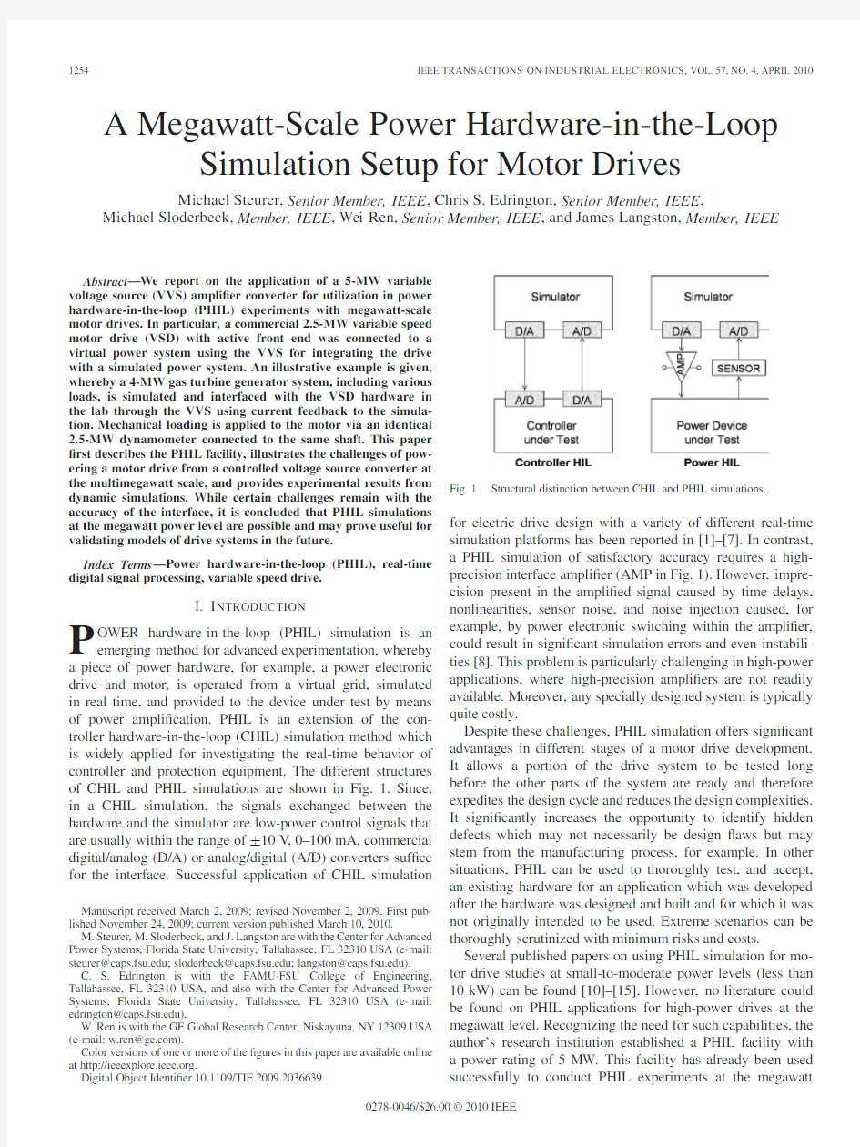
P OWER hardware-in-the-loop(PHIL)simulation is an emerging method for advanced experimentation,whereby a piece of power hardware,for example,a power electronic drive and motor,is operated from a virtual grid,simulated in real time,and provided to the device under test by means of power ampli?cation.PHIL is an extension of the con-troller hardware-in-the-loop(CHIL)simulation method which is widely applied for investigating the real-time behavior of controller and protection equipment.The different structures of CHIL and PHIL simulations are shown in Fig.1.Since, in a CHIL simulation,the signals exchanged between the hardware and the simulator are low-power control signals that are usually within the range of±10V,0–100mA,commercial digital/analog(D/A)or analog/digital(A/D)converters suf?ce for the interface.Successful application of CHIL simulation
Manuscript received March2,2009;revised November2,2009.First pub-lished November24,2009;current version published March10,2010.
M.Steurer,M.Sloderbeck,and https://www.doczj.com/doc/644691301.html,ngston are with the Center for Advanced Power Systems,Florida State University,Tallahassee,FL32310USA(e-mail: steurer@https://www.doczj.com/doc/644691301.html,;sloderbeck@https://www.doczj.com/doc/644691301.html,;langston@https://www.doczj.com/doc/644691301.html,). C.S.Edrington is with the FAMU-FSU College of Engineering, Tallahassee,FL32310USA,and also with the Center for Advanced Power Systems,Florida State University,Tallahassee,FL32310USA(e-mail: edrington@https://www.doczj.com/doc/644691301.html,).
W.Ren is with the GE Global Research Center,Niskayuna,NY12309USA (e-mail:w.ren@https://www.doczj.com/doc/644691301.html,).
Color versions of one or more of the?gures in this paper are available online at https://www.doczj.com/doc/644691301.html,.
Digital Object Identi?er
10.1109/TIE.2009.2036639
Fig.1.Structural distinction between CHIL and PHIL simulations.
for electric drive design with a variety of different real-time
simulation platforms has been reported in[1]–[7].In contrast,
a PHIL simulation of satisfactory accuracy requires a high-
precision interface ampli?er(AMP in Fig.1).However,impre-
cision present in the ampli?ed signal caused by time delays,
nonlinearities,sensor noise,and noise injection caused,for
example,by power electronic switching within the ampli?er,
could result in signi?cant simulation errors and even instabili-
ties[8].This problem is particularly challenging in high-power
applications,where high-precision ampli?ers are not readily
available.Moreover,any specially designed system is typically
quite costly.
Despite these challenges,PHIL simulation offers signi?cant
advantages in different stages of a motor drive development.
It allows a portion of the drive system to be tested long
before the other parts of the system are ready and therefore
expedites the design cycle and reduces the design complexities.
It signi?cantly increases the opportunity to identify hidden
defects which may not necessarily be design?aws but may
stem from the manufacturing process,for example.In other
situations,PHIL can be used to thoroughly test,and accept,
an existing hardware for an application which was developed
after the hardware was designed and built and for which it was
not originally intended to be used.Extreme scenarios can be
thoroughly scrutinized with minimum risks and costs.
Several published papers on using PHIL simulation for mo-
tor drive studies at small-to-moderate power levels(less than
10kW)can be found[10]–[15].However,no literature could
be found on PHIL applications for high-power drives at the
megawatt level.Recognizing the need for such capabilities,the
author’s research institution established a PHIL facility with
a power rating of5MW.This facility has already been used
successfully to conduct PHIL experiments at the megawatt 0278-0046/$26.00?2010IEEE
Fig.2.Facility layout used for PHIL experiments.
level.Initially set up with a mechanical interface(AMP in Fig.1)in the form of controllable dynamometers,the?rst PHIL experiment conducted in this facility was the testing of a novel ship-propulsion-type motor[16].With the addition of an electrical interface(again,AMP in Fig.1),PHIL experiments with a superconducting fault current limiter became possible and were reported in[17].Only the portion of the facility used in the work reported in this paper is described brie?y in the next section.A more detailed description of the entire facility can be found in[18].
II.O VERVIEW OF PHIL S ETUP
Fig.2shows the facility layout as it was used for the results reported in this paper.In this particular setup,the real-time digital simulator(RTDS)[19]contains the power system simulation with which the device under test interacts.Typical time steps of the simulation used for PHIL experiments at this facility are50μs.That time step matches well with the band-width of the ampli?er converter,annotated as variable voltage source(VVS),parts one and two(VVS1and VVS2),in Fig.2, which ranges between approximately40Hz and1kHz.Both portions of the VVS are bidirectional converters comprising an active front-end stage that is transformer connected to the 4.16-kV side of the utility supply.In normal ampli?er mode,the output of the inverter stage is controllable in voltage magnitude from near zero to the full line-to-line voltage of4.16kV at the experimental bus.Furthermore,the fundamental frequency of the requested output can range from approximately40to 65Hz.In addition,the VVS employs a manufacturer-supplied harmonic voltage control in order to maintain a harmonic volt-
age spectrum as requested by the reference voltages supplied by
the simulator.In bypass mode,the VVS accepts,at its reference
inputs,instantaneous voltage waveforms from the simulator,
which are passed directly to the pulsewidth modulator of the
inverter section.The latter switches at effectively10kHz by
utilizing a twin connection scheme[21]at its step-up(output)
transformers T6and T7,respectively.In all the PHIL experi-
ments described herein,only VVS1was used and operated in
bypass mode.
In addition to the VVS,the facility also contains two iden-
tical2.5-MW dynamometers,namely,M1and M2,which are
connected on a single shaft and powered by two identical com-
mercial off-the-shelf variable speed motor drive(VSD)units,
namely,VSD1and VSD2.Both drives can accept either speed
or torque references from the simulator.Like the VVS,both
drives are bidirectional and allow full four quadrant operation of
the dynamometers.The drives are neutral-point-diode-clamped
three-level back-to-back converters with an active front end
which utilizes a?xed-pattern pulsewidth-modulation scheme
and maintains unity power factor at the4.16-kV side of T2
and T3.Normally,both VSD1and VSD2are connected to the
4.16-kV utility bus for operating M1and M2in tandem as
dynamometers against any customer-supplied mechanical load.
However,for the PHIL experiments described herein,the output
of VVS1was connected to the drive transformer T2of VSD1,
hence powering VSD1from the experimental bus.
III.M ETHODOLOGY FOR PHIL E XPERIMENTS
With the setup shown in Fig.2,we conducted two sets of
PHIL experiments.The?rst set of PHIL experiments modeled
a notional power system comprising a gas turbine generator and
two controllable loads,as shown in Fig.3.A4-MW/5-MV A
dq-axis synchronous machine model with a voltage regula-tor/exciter,prime mover,and governor represents the generator.
The synchronous machine model is a component of the RTDS
simulator library and includes mechanical inertia and damping
parameters,as well as typical electrical characteristics.An aero-
derivative twin-shaft gas turbine model,based on the study
in[22],is used that includes details of the governor,com-
bustion chamber,and exhaust gas temperature measurement
time constants.The simulated electrical system is shown in
Fig.3,in one-line format.The controllable resistive load and
current sources are connected in Y and are ungrounded.The
controllable inductive load is connected in Y to ground.The
nodes labeled as ATG1A,ATG1B,and ATG1C represent points
at which the bus voltage is extracted as a reference that is subse-
quently fed into the VVS1controller in order to reproduce the
simulated bus voltages at its output.Incorporation of the VSD1
that exists in the real world is accomplished via controllable
current sources,as shown on the far right-hand side of Fig.3.
The controlling quantities of those current sources are the three
phase currents measured at the4.16-kV side of the transformer
T2(shown in Fig.2).This yields an ideal transformer interface
for the PHIL simulation.As described in more detail in[8],
such an interface is the simplest one to implement but may
be prone to instabilities.Therefore,a?rst-order low-pass?lter
from VVS1.
to100%of rated speed which is225r/min(note that M1and M2are designed to operate up to450r/min at constant power). Accordingly,the apparent power at the bus increases from 250kW to1.25MW,while the combined inertia of M1and M2 was accelerated.Similar results with reverse power?ow were obtained when decelerating from100%to zero speed. Despite the discrepancies between the two traces in Fig.4 before and after the ramp,they match very well during the ramp in the high-current regime.The difference in the low-current regime can be explained by the traces of the instanta-neous currents during approximately two60-Hz cycles shown
in Fig.5.In grid-connected mode,the VSD1draws more
Fig.6.Instantaneous voltage waveform at the4.16-kV side of T2when connected to the grid or when powered from VVS1and reference voltage. harmonic current because the impedance is approximately1/3 of that when the VSD1is connected to VVS1.
Fig.6shows the instantaneous voltage waveform at the 4.16-kV side of T2when connected to the grid or when pow-ered from VVS1.Clearly visible are pronounced notches and increased ringing at the instances when the power electronic de-vices of VSD1are switching.In comparison,the voltage during grid supply is much smoother,and so is the reference sent from the simulator.The discrepancies can be explained as follows.
1)The combined impedance of the laboratory utility bus
amounts to only2%.Therefore,no signi?cant notching appears when VSD1is operated from the grid.
2)The?lter on the feedback currents in the PHIL case
further reduces those notching transients.Therefore,the reference voltage shown in Fig.6does not show any visible notching.
3)Even if the reference did contain the notching transients,
such a distorted reference voltage cannot be reproduced accurately by the VVS in the required frequency range, which here is greater than3kHz.
4)Finally,the combined impedance of T6and the inductive
?lter between T6and VVS1amounts to6%.Because the VVS1was operated in bypass mode,no closed-loop voltage control was available to compensate for the voltage drops across that impedance. Unfortunately,the voltage control supplied by the manufac-turer of VVS1was not able to maintain a stable operation when subjected to the severe notching shown in Fig.6.The lack of closed-loop voltage control also presents a small time lag of approximately350μs between the reference voltage sent by the simulator and the voltage produced at the experimental bus. Note that this time lag includes at least one simulation time step just from capturing the data within the simulator.
Due to the fact that VSD1operates at unity power factor and because the simulated impedance is only2%,the highest voltage drop expected is only1%and phase shifted by90?with respect to the line voltage.Therefore,the effect of current feedback was negligible in the validation case.In order to illus-trate the effect of current feedback into the simulated system, we inserted an arti?cial8.3%resistance between T1and
T2Fig.7.RMS voltages at the4.16-kV side of T2when VSD1is operated from VVS1with and without current feedback into the simulation(with arti?cial resistor modeled between T1and
T2).
Fig.8.Instantaneous current waveforms into T2when VSD1is operated from VVS1with and without current feedback into the simulation(with arti?cial resistor modeled between T1and T2).
to achieve a relevant voltage drop in the system.Fig.7clearly shows the effect of that current feedback.Without feedback, the measured voltage drops by less than1.5%during a speed ramp.This voltage drop is caused only by the6%reactance of the VVS1and T6.However,with current feedback into the simulation,an additional voltage drop of approximately3.5% becomes evident,close to the4%expected from0.5-p.u.current (compare Fig.4)and8.3%resistance.
Finally,Fig.8shows the instantaneous current waveforms into T2with and without current feedback into the simulation which contained the arti?cial8.3%resistance between T1and T2.Since,in both cases,VSD1required the same input power for the speed ramp,the current is lower when no feedback was applied because the voltage on the4.16-kV experimental bus was higher.In addition,the feedback current is also shown in Fig.8.The phase lag of approximately300μs caused by the ?lter is clearly visible.
B.Notional Gas Turbine Cases
The experimental data are presented as a series of three cases using the simulation model described earlier in Fig.3.As
TABLE I
E XPERIMENTAL PHIL C ASES W ITH N OTIONAL G AS T URBINE S
YSTEM
Fig.9.Generator data for case I.
opposed to the validation cases,the dynamometer M2provided load torque to M1.As shown earlier in Fig.2,the VSD2, which operated M2,was connected to the laboratory utility bus, whereas VSD1was connected to the“ampli?er”VVS1.The detail for each case is shown in Table I.
All the experiments were carried out at168.75r/min or75% of the225-r/min rated speed of M1and M2.The torque is given in percent of the106-kN·m rated torque.All other data are given in per unit or percent based on5MV A at4.16kV.The generator frequency is given in per unit based on60Hz.
1)CASE I—Step Load:Fig.9shows the simulated gener-ator data after a2-MW resistive load step applied at0.25s. The system prior to the load step depicts a real power output by the generator of approximately0.16p.u.or0.8MW.This power draw stems from the base resistive load plus the power demanded by VSD1.After the resistive load step,the real power output from the generator is approximately0.56p.u.or 2.8MW.Since the load torque provided by M2is constant, there is no?uctuation in the real power in the steady state. The reactive power output by the generator remains constant at approximately0.17p.u.The voltage sag of1%in generator output voltage during the step change is also shown in Fig.9.In addition,corresponding to the voltage change is an accompany-ing total frequency change of less than0.02p.u.when the gas turbine governor adjusts fuel injection to accommodate for the increased power demand.It should be emphasized here that the change in the simulated generator bus voltage magnitude and frequency is reproduced in the real world by the experimental bus voltage supplied to VSD1by
VVS1.Fig.10.Measured voltage at experimental bus for case
I.
Fig.11.Generator data for case II.
Fig.10shows the measured waveforms of all three phase voltages at the experimental bus(V MEAS between T6and T2 in Fig.2)prior to the resistive load step.As expected,VVS1 provides a balanced voltage system to the load.
2)CASE II—Ramping Inductive Load:In this case,an in-ductive load change was introduced by linearly ramping the inductance in Fig.3from60down to20mH within0.8s. The moderately slow ramp rate was chosen to easily maintain voltage stability in the system.Fig.11shows the generator data for this event.As the shunt inductance is ramped down,the generator voltage sags by0.03p.u.since the reactive power of that load increases from approximately0.15to0.46p.u.The total reactive power draw in Fig.11is slightly higher since the phase shift caused by the?lter applied to the feedback current makes the unity power factor load presented by VSD1 to appear slightly reactive.Except for a very small transient,the generator frequency stays at1p.u.because the real power draw was unaffected by the event.
3)CASE III—Torque Oscillations:In this case,the average load torque between M1and M2,the machines operating in the real world,is increased to40%.Moreover,the dynamome-ter is controlled such that a torque oscillation of±10%is
Fig.12.Generator data for case III.
superimposed on the average torque(see Table I for details). Fig.12shows the generator data for this PHIL simulation. As the motor drive operating in speed mode compensates for the oscillating torque load,the real power required from the generator oscillates accordingly.These oscillations in generator output power are also re?ected in the generator frequency. Since VSD1operates at unity power factor,no oscillations are observed in the reactive power.Note that most of the 0.2-p.u.reactive load originates from the shunt reactors in the simulation case set at50mH.The remainder of the reactive load stems from the arti?cial reactive power demand by VSD1, which appears in the simulation due to the phase lag in the ?ltered feedback current.Moreover,it is shown in Fig.12that the generator output voltage is?at as expected,with negligible oscillations in reactive power.
V.C ONCLUSION
This paper has presented the?rst application of PHIL ex-periments with a commercial motor drive at the megawatt power level.From the work presented herein,we conclude the following.
1)PHIL experiments at the megawatt power level with cou-
pling between simulation and experiment at the electrical interface are possible even when operating a multilevel self-commutated active front end of a medium-voltage motor drive from the output of another power electronic converter of similar power rating.
2)The setup presented in this paper is well suited to al-
low PHIL experiments with representatively large mo-tor drives.Such experimentation is expected to be very useful to thoroughly validate models of megawatt-scale drive systems under all relevant electrical system conditions.
3)While the open-loop control of the simulated voltage
at the experimental bus is suf?cient for the dynamic cases presented in this paper,additional work is clearly needed to implement a closed-loop voltage control in order to make the ampli?er more transparent to the PHIL simulation.
R EFERENCES
[1]S.Vamsidhar and B.G.Fernandes,“Hardware-in-the-loop simulation
based design and experimental evaluation of DTC strategies,”in Proc.
IEEE35th Annu.PESC,Jun.20–25,2004,vol.5,pp.3615–3621.
[2]M.Akar and J. C.Kalkkuhl,“Design and evaluation of an in-
tegrated chassis controller for automotive vehicle emulation,”IEEE Trans.Ind.Electron.,vol.56,no.9,pp.3571–3579,Sep.2009,DOI:
10.1109/TIE.2009.201368.
[3]J.Gamez García,J.Gómez Ortega,A.Sánchez García,and S.Satorres
Martínez,“Robotic software architecture for multisensor fusion system,”
IEEE Trans.Ind.Electron.,vol.56,no.3,pp.766–777,Mar.2009,DOI:
10.1109/TIE.2008.2007014.
[4]B.Lu,X.Wu,H.Figueroa,and A.Monti,“A low-cost real-time hardware-
in-the-loop testing approach of power electronics controls,”IEEE Trans.
Ind.Electron.,vol.54,no.2,pp.919–931,Apr.2007.
[5]C.Dufour,S.Abourida,and J.Belanger,“Real-time simulation of per-
manent magnet motor drive on FPGA chip for high-bandwidth controller tests and validation,”in Proc.IEEE Int.Ind.Electron.,Jul.9–13,2006, vol.3,pp.2591–2596.
[6]S.Abourida, C.Dufour,J.Belanger,T.Yamada,and T.Arasawa,
“Hardware-in-the-loop simulation of?nite-element based motor drives with RT-LAB and JMAG,”in Proc.IEEE Int.Symp.Ind.Electron., Jul.9–13,2006,vol.3,pp.2462–2466.
[7]K.Terada and N.Uchida,Multi-domain simulation of drive controls,
Mitsubishi Elect.Corp.,Tokyo,Japan.[Online].Available:http://global.
https://www.doczj.com/doc/644691301.html,/company/rd/advance/pdf/vol116/vol116_tr5.pdf [8]W.Ren,M.Steurer,and T.L.Baldwin,“Improve the stability of
power hardware-in-the-loop simulation by selecting appropriate inter-face algorithm,”IEEE Trans.Ind.Appl.,vol.44,no.4,pp.1286–1294, Jul./Aug.2008.
[9]W.Ren,M.Steurer,and T.L.Baldwin,“An effective method for evalu-
ating the accuracy of power hardware-in-the-loop simulations,”in Proc.
IEEE/IAS ICPS,May4–8,2008,pp.1–6.
[10]H.J.Slater,D.J.Atkinson,and A.G.Jack,“Real-time emulation for
power equipment development.II.The virtual machine,”Proc.Inst.Elect.
Eng.—Elect.Power Appl.,vol.145,no.3,pp.153–158,May1998. [11]X.Wu,S.Lentijo,A.Deshmuk,A.Monti,and F.Ponci,“Design and
implementation of a power-hardware-in-the-loop interface:A nonlinear load case study,”in Proc.20th Annu.IEEE APEC,Mar.6–10,2005,vol.2, pp.1332–1338.
[12]A.Bouscayrol,X.Guillaud,P.Delarue,and B.Lemaire-Semail,“Ener-
getic macroscopic representation and inversion-based control illustrated on a wind energy conversion systems using hardware-in-the-loop si-mulation,”IEEE Trans.Ind.Electron.,vol.56,no.12,pp.4826–4835, Dec.2009,DOI:10.1109/TIE.2009.2013251.
[13]H.Li,M.Steurer,K.L.Shi,S.Woodruff,and D.Zhang,“Development
of a uni?ed design,test,and research platform for wind energy systems based on hardware-in-the-loop real-time simulation,”IEEE Trans.Ind.
Electron.,vol.53,no.4,pp.1144–1151,Jun.2006.
[14]W.Ren,M.Steurer,and S.Woodruff,“Applying controller and power
hardware-in-the-loop simulation in designing and prototyping apparatuses for future all electric ship,”in Proc.IEEE Elect.Ship Technol.Symp., Arlington,V A,May21–23,2007,pp.443–448.
[15]H.M.Kojabadi,L.Chang,and T.Boutot,“Development of a novel wind
turbine simulator for wind energy conversion systems using an inverter-controlled induction motor,”IEEE Trans.Energy Convers.,vol.19,no.3, pp.547–552,Sep.2004.
[16]M.Steurer,S.Woodruff,T.Baldwin,H.Boenig,F.Bogdan,T.Fikse,
M.Sloderbeck,and G.Snitchler,“Hardware-in-the-loop investigation of rotor heating in a5MW HTS propulsion motor,”IEEE Trans.Appl.
Supercond.,vol.17,pt.2,no.2,pp.1595–1598,Jun.2007.
[17]C.Schacherer,https://www.doczj.com/doc/644691301.html,ngston,M.Steurer,and M.Noe,“Power hardware-
in-the-loop testing of a YBCO coated conductor fault current limiting module,”IEEE Trans.Appl.Supercond.—Special Issue From the Applied Superconductivity Conference,vol.19,no.3,pp.1801–1805,Jun.2009.
[18]M.Sloderbeck, F.Bogdan,J.Hauer,L.Qi,and M.Steurer,“The
addition of a5MW variable voltage source to a hardware-in-the-loop simulation and test facility,”in Proc.EMTS,Philadelphia,PA, Aug.12–13,2008.
[19]R.Kuffel,J.Giesbrecht,T.Maguire,R.P.Wierckx,and P.G.McLaren,
“RTDS—A fully digital power system simulator operating in real time,”
in Proc.IEEE WESCANEX,1995,vol.2,pp.300–305.
[20]R.Kuffel,R.P.Wierckx,H.Duchen,https://www.doczj.com/doc/644691301.html,gerkvist,X.Wang,P.Forsyth,
and P.Holmberg,“Expanding an analogue HVDC simulator’s modeling capability using a Real-Time Digital Simulator(RTDS),”in Proc.1st ICDS,Apr.1995,p.199.
[21]S.Ponnaluri,J.K.Steinke,P.Steimer,S.Reichert,and B.Buchmann,
“Design comparison and control of medium voltage STATCOM with novel twin converter topology,”in Proc.35th Annu.IEEE PESC,2004, vol.4,pp.2546–2552.
[22]L.N.Hannett,G.Lee,and B.Fardanesh,“A governor/turbine model for
a twin-shaft combustion turbine,”IEEE Trans.Power Syst.,vol.10,no.1,
pp.133–140,Feb.
1995.
Michael Steurer(M’01–SM’07)received the M.E.E.degree from the Vienna University of Technology,Vienna,Austria,in1995and the Ph.D. degree in technical science from the Swiss Federal Institute of Technology,Zurich,Switzerland, in2001.
He is currently a Senior Researcher with the Center for Advanced Power Systems,Florida State University,Tallahassee,where he leads the power systems group focusing on hardware-in-the-loop simulation and modeling of integrated power sys-
tems for all-electric ships and future terrestrial power systems.He has authored and coauthored more than20peer-reviewed technical papers in electric power apparatus and their system interactions.
Dr.Steurer is a member of the International Council on Large Electric Systems(CIGRE).He is the Chairman of the IEEE Task Force on“Fault Current Limiter Testing.”He contributes to the CIGRE Working Group A3.23“Application and Feasibility of Fault Current Limiters in Power Systems,”IEEE Working Group I8“Power Electronic Building Blocks,”IEEE Working Group P1709“Recommended Practice for1to35kV Medium V oltage DC Power
Systems on Ships,”and the Task Force on“Dynamic System
Equivalents.”
Chris S.Edrington(S’94–M’04–SM’09)received
the Ph.D.degree in electrical engineering from the
University of Missouri,Rolla,in2004.
From2004to2007,he was an Assistant Pro-
fessor of electrical engineering with the College of
Engineering,Arkansas State University,Jonesboro.
He is currently an Assistant Professor of electri-
cal engineering with the College of Engineering,
Tallahassee,FL,and a Research Associate with the
Center for Advanced Power Systems,Florida State
University,Tallahassee.His research interests in-clude modeling,simulation,and control of electromechanical drive systems; applied power electronics;and integration of renewable energy.
Dr.Edrington was a fellow of Graduate Assistance in Areas of National Need and Integrative Graduated Education and Research
Traineeship.
Michael Sloderbeck(M’87)received the M.S.de-
gree in computer science from the Florida State
University,Tallahassee,in1990.
Since2002,he has been with the Center for
Advanced Power Systems,Florida State University,
where he works on the development of hardware-in-
the-loop techniques for real-time
simulation.
Wei Ren(S’05–M’08–SM’09)received the B.S.
degree in electrical engineering from Shanghai Jiao
Tong University,Shanghai,China,in1999and the
Ph.D.degree in power system from the Florida State
University,Tallahassee,in2007.
From2007to2008,he was a Postdoctoral
Fellow with the Center for Advanced Power
Systems,Florida State University,where he spe-
cialized in integrated power system modeling,real-
time hardware-in-the-loop simulation,and?exible
alternating-current transmission system device oper-ation and control.Since2008,he has been with the GE Global Research Center, Niskayuna,NY,as an Electric Power Engineer,with research focusing on wind power control and integration and on smart grid operation and
optimization.
James Langston(M’98)received the B.S.and M.S.
degrees in electrical engineering from the Florida
State University,Tallahassee,in2000and2002,
respectively.
He is currently an Assistant in research with the
Center for Advanced Power Systems,Florida State
University,working on modeling and simulation of
power systems.
易存云存储系统平台建设 项目方案 北京易存科技 2016-1-25 目录 一、方案概述....................................... (03) 二、方案要求与建设目标.................................0 4 2.1 客户需求分析..................................04 2.2 系统主要功能方案..............................05 三、系统安全方案.................................... (19) 3.1 系统部署与拓扑图...............................19 3.2 文件存储加密...................................21 3.3 SSL协议........................................22 3.4 二次保护机制............................. (23)
3.5 备份与恢复.....................................23 四、系统集成与二次开发.................................24 4.1 用户集成.......................................24 4.2 文件集成.................................... (2) 7 4.3 二次开发.................................... (2) 9 五、典型成功案例.......................................29 六、售后服务体系.................................... (30) 6.1公司概况.......................................30 6.2 服务内容与响应时间............................. 31 一、方案概述 随着互联网时代的到来,企业信息化让电子文档成为企业智慧资产的主要载体。信息流通的速度、强度和便捷度的加强,一方面让我们享受到了前所未有的方便和迅捷,但另一方面也承受着信息爆炸所带来的压力。 传统的文件管理方式已经无法满足企业在业务的快速发展中对文件的安全而高效流转的迫切需求。尤其是大文件的传输与分享,集团公司与分公司,部门与部门之间,乃至与供应商或客户之间频繁的业务往来,显得尤其重要。 文件权限失控严重,版本混乱,传递效率,查找太慢,文件日志无法追溯,历史纸质文件管理与当前业务系统有效整合对接等一系列的问题日渐变的突出和迫切。 该文档描述了北京易存科技为企业搭建文档管理系统平台的相关方案。从海量文件的存储与访问,到文件的使用,传递,在线查看,以及文件的流转再到归档
云课堂 技术解决方案
目录 第1章概述 (2) 第2章现状分析及问题 (3) 2.1方案背景 (3) 2.2教育信息化建设的发展 (3) 2.2云课堂的推出 (4) 第3章云课堂技术解决方案 (5) 3.1云终端方案概述 (5) 3.2云课堂解决方案 (5) 3.2.1 云课堂拓扑图 (5) 3.2.2 云课堂教学环境 (6) 3.2.3 云课堂主要功能 (7) 3.2.4 优课数字化教学应用系统功能 (8) 第4章方案优势 (9) 4.1私密性 (9) 4.2工作连续性 (9) 4.3方便移动性 (9) 4.4场景一致性 (9) 4.5长期积累性 (9) 4.6安全稳定性 (10) 4.7易维护性 (10) 4.8高效性 (10) 第5章实际案例 (11)
第1章概述 随着现代信息技术的飞速发展,越来越多的用户更加注重自身信息架构的简便易用性、安全性、可管理性和总体拥有成本。近几年信息化的高速发展,迫使越来越多的教育机构需要采用先进的信息化手段,解决各机构当前面临的数据安全隔离、信息共享、资源整合等实际问题,实现通过改进机器的利用率降低成本,减少管理时间和降低基础设施成本,提高工作效率。 无论是作为云计算的核心技术,还是作为绿色 IT、绿色数据中心的核心技术,虚拟化已经成为 IT 发展的重要方向,也可以说我们正面临着一场 IT 虚拟化、云计算的革命。这场 IT 虚拟化、云计算的革命正在开始席卷全球。 虚拟化技术在解决信息安全、资源利用率提升、简化 IT 管理、节能减排等方面有着得天独厚的优势,通过虚拟化技术,把数据中心的计算资源和存储资源发布给终端用户共享使用,大幅度提高服务器资源利用率,同时通过严格的访问控制,确保数据中心中所存储的安全性。
《数据结构》实验指导书 郑州轻工业学院 2016.02.20
目录 前言 (3) 实验01 顺序表的基本操作 (7) 实验02 单链表的基本操作 (19) 实验03 栈的基本操作 (32) 实验04 队列的基本操作 (35) 实验05 二叉树的基本操作 (38) 实验06 哈夫曼编码 (40) 实验07 图的两种存储和遍历 (42) 实验08 最小生成树、拓扑排序和最短路径 (46) 实验09 二叉排序树的基本操作 (48) 实验10 哈希表的生成 (50) 实验11 常用的内部排序算法 (52) 附:实验报告模板 .......... 错误!未定义书签。
前言 《数据结构》是计算机相关专业的一门核心基础课程,是编译原理、操作系统、数据库系统及其它系统程序和大型应用程序开发的重要基础,也是很多高校考研专业课之一。它主要介绍线性结构、树型结构、图状结构三种逻辑结构的特点和在计算机内的存储方法,并在此基础上介绍一些典型算法及其时、空效率分析。这门课程的主要任务是研究数据的逻辑关系以及这种逻辑关系在计算机中的表示、存储和运算,培养学生能够设计有效表达和简化算法的数据结构,从而提高其程序设计能力。通过学习,要求学生能够掌握各种数据结构的特点、存储表示和典型算法的设计思想及程序实现,能够根据实际问题选取合适的数据表达和存储方案,设计出简洁、高效、实用的算法,为后续课程的学习及软件开发打下良好的基础。另外本课程的学习过程也是进行复杂程序设计的训练过程,通过算法设计和上机实践的训练,能够培养学生的数据抽象能力和程序设计能力。学习这门课程,习题和实验是两个关键环节。学生理解算法,上机实验是最佳的途径之一。因此,实验环节的好坏是学生能否学好《数据结构》的关键。为了更好地配合学生实验,特编写实验指导书。 一、实验目的 本课程实验主要是为了原理和应用的结合,通过实验一方面使学生更好的理解数据结构的概念
第一章 3.(1)A(2)C(3)D 5.计算下列程序中x=x+1的语句频度 for(i=1;i<=n;i++) for(j=1;j<=i;j++) for(k=1;k<=j;k++) x=x+1; 【解答】x=x+1的语句频度为: T(n)=1+(1+2)+(1+2+3)+……+(1+2+……+n)=n(n+1)(n+2)/6 6.编写算法,求一元多项式p n(x)=a0+a1x+a2x2+…….+a n x n的值p n(x0),并确定算法中每一语句的执行次数和整个算法的时间复杂度,要求时间复杂度尽可能小,规定算法中不能使用求幂函数。注意:本题中的输入为a i(i=0,1,…n)、x和n,输出为P n(x0)。算法的输入和输出采用下列方法 (1)通过参数表中的参数显式传递 (2)通过全局变量隐式传递。讨论两种方法的优缺点,并在算法中以你认为较好的一种实现输入输出。 【解答】 (1)通过参数表中的参数显式传递 优点:当没有调用函数时,不占用内存,调用结束后形参被释放,实参维持,函数通用性强,移置性强。 缺点:形参须与实参对应,且返回值数量有限。 (2)通过全局变量隐式传递 优点:减少实参与形参的个数,从而减少内存空间以及传递数据时的时间消耗 缺点:函数通用性降低,移植性差 算法如下:通过全局变量隐式传递参数 PolyValue() { int i,n; float x,a[],p; printf(“\nn=”); scanf(“%f”,&n); printf(“\nx=”); scanf(“%f”,&x); for(i=0;i 云安全管理平台解决方案 北信源云安全管理平台解决方案北京北信源软件股份有限公司 2010 云安全管理平台解决方案/webmoney 2.1问题和需求分析 2.2传统SOC 面临的问题................................................................... ...................................... 4.1资产分布式管理 104.1.1 资产流程化管理 104.1.2 资产域分布 114.2 事件行为关联分析 124.2.1 事件采集与处理 124.2.2 事件过滤与归并 134.2.3 事件行为关联分析 134.3 资产脆弱性分析 144.4 风险综合监控 154.4.1 风险管理 164.4.2 风险监控 174.5 预警管理与发布 174.5.1 预警管理 174.5.2 预警发布 194.6 实时响应与反控204.7 知识库管理 214.7.1 知识共享和转化 214.7.2 响应速度和质量 214.7.3 信息挖掘与分析 224.8 综合报表管理 245.1 终端安全管理与传统SOC 的有机结合 245.2 基于云计算技术的分层化处理 255.3 海量数据的标准化采集和处理 265.4 深入事件关联分析 275.5 面向用户服务的透明化 31云 安全管理平台解决方案 /webmoney 前言为了不断应对新的安全挑战,越来越多的行业单位和企业先后部署了防火墙、UTM、入侵检测和防护系统、漏洞扫描系统、防病毒系统、终端管理系统等等,构建起了一道道安全防线。然而,这些安全防线都仅仅抵御来自某个方面的安全威胁,形成了一个个“安全防御孤岛”,无法产生协同效应。更为严重地,这些复杂的资源及其安全防御设施在运行过程中不断产生大量的安全日志和事件,形成了大量“信息孤岛”,有限的安全管理人员面对这些数量巨大、彼此割裂的安全信息,操作着各种产品自身的控制台界面和告警窗口,显得束手无策,工作效率极低,难以发现真正的安全隐患。另一方面,企业和组织日益迫切的信息系统审计和内控要求、等级保护要求,以及不断增强的业务持续性需求,也对客户提出了严峻的挑战。对于一个完善的网络安全体系而言,需要有一个统一的网络安全管理平台来支撑,将整个网络中的各种设备、用户、资源进行合理有效的整合,纳入一个统一的监管体系,来进行统一的监控、调度、协调,以达到资源合理利用、网络安全可靠、业务稳定运行的目的。云安全管理平台解决方案 /webmoney 安全现状2.1 问题和需求分析在历经了网络基础建设、数据大集中、网络安全基础设施建设等阶段后,浙江高法逐步建立起了大量不同的安全子系统,如防病毒系统、防火墙系统、入侵检测系统等,国家主管部门和各行业也出台了一系列的安全标准和相关管理制度。但随着安全系统越来越庞大,安全防范技术越来越复杂,相关标准和制度越来越细化,相应的问题也随之出现: 1、安全产品部署越来越多,相对独立的部署方式使各个设备独立配置、管理,各产品的运行状态如何?安全策略是否得到了准确落实?安全管理员难以准确掌握,无法形成全局的安全策略统一部署和监控。 2、分散在各个安全子系统中的安全相关数据量越来越大,一方面海量数据的集中储存和分析处理成为问题;另一方面,大量的重复信息、错误信息充斥其中,海量的无效数据淹没了真正有价值的安全信息;同时,从大量的、孤立的单条事件中无法准确地发现全局性、整体性的安全威胁行为。 3、传统安全产品仅仅面向安全人员提供信息,但管理者、安全管理员、系统管理 基于PowerBuilder 的学生成绩管理系统的设计与实 信息社会的高科技,商品经济化的高效益,使计算机的应用已普及到经济和社会生活的各个领域。计算机虽然与人类的关系愈来愈密切,但还有由于计算机操作不方便而继续用手工进行劳动的人。学生成绩管理和分析系统为教务人员带来了极大的方便。该软件是以汉语编程语言为实现语言,其功能在系统内部有源代码直接完成。通过操作手册,使用者可以了解本软件的基本工作原理。操作人员只需输入一些简单的汉字、数字,即可达到自己的目的。 现今成绩管理的繁琐给教务人员带来了诸多不便,教学办公室缺少一种完善的成绩管理软件,为了方便的管理学生成绩,因此开发了此学生成绩管理和分析系统。 学生成绩管理和分析系统的目标: 1)节约资源,提高学生信息的精确度:能够减少很多不必要的资源,不用像以前那样用冗余的纸张式的管理。大大节省了学院资源。并且计算机的存储与快速查询功能大大提高了学生成绩管理的效率,并且还提高了成绩信息管理的精确度。 2)方便快速的操作,精简人员,节约开支:方便快速的操作,可减少学生信息管理的漏洞,又可减少工作的错误,并且操作非常简单,可减少许多不必要的工作人员,这无论从物质上还 是工作人员的工资上都为学院节约了开支,为学院增加了财富。 1系统分析 成绩管理系统主要针对三类用户:学生、教师、管理员。 个良好的成绩管理系统不仅要求有方快捷的操作、简单有效的管理,而且要有高级的安全性以及很强的通用性。根据需求分析,使用面向对象的设计技术,系统应具有如下的几个功能模块: 1) 用户登录模块 学生用户和教师用户登录以后只能输入相关查询条件进行一系列相关的成绩查询。 管理员登录以后不仅有学生用户和教师用户的所有权限,且可以对数据库和基础信息进行维护。 2) 系统维护模块 若系统在应用过程中出现问题确实需要进行初始化时,系统 管理员就可以对系统进行初始化操作。 3)基本信息维护模块 在此模块中,系统管理员可以对基本信息进行维护,如对班级信息、学生信息、课程信息等进行维护。 4)数据库管理模块 此模块可以对数据库中的数据进行备份和还原。 5)成绩管理模块 此模块只有管理员有权限进行操作,管理员登录后可以对学生成绩进行插入、删除、修改、保存等操作并且能导入和导出学 根式函数值域 HUA system office room 【HUA16H-TTMS2A-HUAS8Q8-HUAH1688】 探究含有根式的函数值域问题 含根式的函数的值域或者最值问题在高中数学的学习过程中时常遇到,因其解法灵活,又缺乏统一的规律,给我们造成了很大的困难,导致有些学生遇到根式就害怕。为此,本文系统总结此类函数值域的求解方法,供学生参考学习。 1.平方法 例1:求31++-=x x y 的值域 解:由题意知函数定义域为[]1,3-,两边同时平方得:322422+--+=x x y =4+()4212+- +x 利用图像可得[]8,42∈y ,又知?y 0[]22,2∈∴y 所以函数值域为[]22,2 析:平方法求值域适用于平方之后可以消去根式外面未知量的题型。把解析式转化为()x b a y ?+=2 的形式,先求y 2 的范围,再得出y 的范围即值域。 2.换元法 例2: 求值域1)12--=x x y 2)x x y 2 4-+= 解:(1)首先定义域为[)+∞,1,令()01≥-=t x t ,将原函数转化为 [)+∞∈,0t ,?? ????+∞∈∴,815y 析:当函数解析式由未知量的整数幂与根式构成,并且根式内外的未知量的次幂保持一致。可以考虑用代数换元的方法把原函数转化成二次函数,再进行值域求解。 (2)首先,函数定义域为[]2,2-∈x ,不妨设αsin 2=x ,令?? ????-∈2,2ππα 则原函数转化为:??? ? ?+=+=4sin 22cos 2sin 2παααy ?? ????-∈2,2ππα,∴??????-∈+43,44πππα 析:形如题目中的解析式,考虑用三角换元的方法,在定义域的前提下,巧妙地规定角的取值范围,避免绝对值的出现。 不管是代数换元还是三角换元,它的目的都是为了去根式,故需要根据题目灵活选择新元,并注意新元的范围。 3.数形结合法 例3:1)求()()8222+-+= x x y 的值域。 2)求1362222+-++-= x x y x x 的最小值。 解:(1)()()8222+-+=x x y 82++-=x x 其解析式的几何意义为数轴上的一动点x ,到两定点2与-8的距离之和,结合数轴不难得到[]+∞∈,10y (2)解析式可转化为()()41312 2+++=--x x y , 定义域为R ,进行适当的变形 ()()=+++--413122x x ()()()()2031012 222----+++x x , 由它的形式联想两点间的距离公式,分别表示点到点的距离与点的距离之和。 点()0,x P 到()1,1A 和()2,3B 的距离之和。即PB PA y +=,结合图形可知 13min =+'=PB A P y ,其中()1,1-'A 析:根据解析式特点,值域问题转化成距离问题,结合图形得出最值,进而求出了值域。 例4:1) 求x x y x 2312 +--+=的值域 学生: 科目: 数 学 教师: 刘美玲 一、二次函数和特殊多边形形状 二、二次函数和特殊多边形面积 三、函数动点引起的最值问题 四、常考点汇总 1、两点间的距离公式:()()22B A B A x x y y AB -+-= 2、中点坐标:线段AB 的中点C 的坐标为:??? ??++22 B A B A y y x x , 直线11b x k y +=(01≠k )与22b x k y +=(02≠k )的位置关系: (1)两直线平行?21k k =且21b b ≠ (2)两直线相交?21k k ≠ (3)两直线重合?21k k =且21b b = (4)两直线垂直?121-=k k 3、一元二次方程有整数根问题,解题步骤如下: ① 用?和参数的其他要求确定参数的取值范围; ② 解方程,求出方程的根;(两种形式:分式、二次根式) ③ 分析求解:若是分式,分母是分子的因数;若是二次根式,被开方式是完全平方式。 例:关于x 的一元二次方程()0122 2 =-m x m x ++有两个整数根,5<m 且m 为整数,求m 的值。 4、二次函数与x 轴的交点为整数点问题。(方法同上) 例:若抛物线()3132 +++=x m mx y 与x 轴交于两个不同的整数点,且m 为正整数,试确定 此抛物线的解析式。 课 题 函数的综合压轴题型归类 教学目标 1、 要学会利用特殊图形的性质去分析二次函数与特殊图形的关系 2、 掌握特殊图形面积的各种求法 重点、难点 1、 利用图形的性质找点 2、 分解图形求面积 教学内容 5、方程总有固定根问题,可以通过解方程的方法求出该固定根。举例如下: 已知关于x 的方程2 3(1)230mx m x m --+-=(m 为实数),求证:无论m 为何值,方程总有一个固定的根。 解:当0=m 时,1=x ; 当0≠m 时,()032 ≥-=?m ,()m m x 213?±-= ,m x 3 21-=、12=x ; 综上所述:无论m 为何值,方程总有一个固定的根是1。 6、函数过固定点问题,举例如下: 已知抛物线22 -+-=m mx x y (m 是常数),求证:不论m 为何值,该抛物线总经过一个固定的点,并求出固定点的坐标。 解:把原解析式变形为关于m 的方程()x m x y -=+-122 ; ∴ ???=-=+-0 1 02 2x x y ,解得:???=-=1 1 x y ; ∴ 抛物线总经过一个固定的点(1,-1)。 (题目要求等价于:关于m 的方程()x m x y -=+-122 不论m 为何值,方程恒成立) 小结.. :关于x 的方程b ax =有无数解????==0 b a 7、路径最值问题(待定的点所在的直线就是对称轴) (1)如图,直线1l 、2l ,点A 在2l 上,分别在1l 、2l 上确定两点M 、N ,使得MN AM +之和最小。 (2)如图,直线1l 、2l 相交,两个固定点A 、B ,分别在1l 、2l 上确定两点M 、N ,使得 AN MN BM ++之和最小。 PB常用函数日期时间类函数 日期时间类函数的功能如下: Date:把日期转换为Date类型。 Time:把时间转换为Time类型。 Day:日期值。 Month:月值。 Year:年值。 DayName:星期几。 DayNumber:一周中的第几天。 DaysAfer:两个日期之间所差的天数。 SecondsAfer:两个时间之间所差的秒数。 Hour:小时。 Minute:分钟。 Second:秒。 Now:系统当前时间。 Today:系统日期和时间。 RelativeDate:指定日期前后的天数值。 RelativeTime:指定时间的前后时间值。 数值计算类函数 数值计算类函数主要的作用就是对数据进行计算,功能如下:Abs:返回数据的绝对值。 Max:求输入的最大值。 Min:求输入的最小值。 Ceiling:返回整数,小数会自动向上进位。 Int:返回整数,小数会自动向下退位。 Round:对数据进行四舍五入操作。 Truncate:删除掉小数点后若干位。 Cos:求余弦值。 Sin:求正弦值。 Tan:求正切值。 Exp:以e为底,输入值为次方的乘方值。 Sqrt:求平方根。 Fact:求阶乘。 Log:求自然对数。 LogTen:求以10为底的对数。 Mod:求余数。 Pi:求与PI的乘积。 Rand:返回1与输入值之间的一个伪随机数。 字符串类函数 字符串类函数的功能如下。 Fill:建立一个指定长度的字符串。 Lower:转换为小写字母。 Upper:转换为大写字母。 WordCap:首写字母大写,其他小写。 Space:由指定字符个数组成的空格字符串。 Left:从字符串左边开始指定字符串。 Right:从字符串右边开始指定字符串。 LeftTrim:删除字符串左边的空格。 RightTrim:删除字符串右边的空格。 Trim:删除左右两边的空格。 Len:返回字符串长度。 Match:判断是否有指定模式的字符。 Mid:取子字符串。 Replace:用指定字符替换另外一个字符串。 String:将数据转换为指定格式的字符串。 信息类函数 信息类函数可以获取数据窗口中的一些信息,函数的功能如下: CurrentRow:获取数据窗口的焦点的行数。 Page:获取当前记录的页数。 PageAcross:获取当前水平方向的页面。 PageCount:获取总页数。 RowHeight:获得记录的高度。 Describe:获取数据窗口对象的属性值。 IsRowModified:获取记录是否修改过,如果修改过返回True。 IsRowNew:获取是否新插入数据,如果插入返回True。 IsSelected:获取记录是否被选中,选中返True。 PageCountAcross:获取水平方向总页面。 RowCount:获取主缓冲区的总记录数。 统计类函数 统计类函数主要是用来对数据库中的数据进行统计操作,统计函数功能如下: Avg:计算字段的平均数,例如Avg(id)。 Max:计算字段的最大值,例如Max(id)。 Min:计算字段的最小值,例如Min(id)。 Median:计算字段的中间值。 Count:计算表或字段的记录数,例如Count(*)。 Frist:返回第一条记录。 Last:返回最后一条记录。 交叉表函数 只能在交叉列表风格的数据窗口中的细节区使用交叉表函数,交叉表的函数功能如下:CrosstabVag:计算字段数据的平均数。 CrosstabCount:计算字段数据的记录数。 CrosstabMax:计算字段数据的最大值。 CrosstabMin:计算字段数据的最小值。 数据类型转换与检查函数 数据类型转换与检查函数用于定义数据窗口的过滤条件、有效性检查和数据类型转换,数据类型转换与检查函数的功能如下: 随着云计算在企业内应用,大多数企业都认识到了云计算的的重要性,因为它可以实现资源分配的灵活性、可伸缩性并且提高了服务器的利用率,降低了企业的成本。但是随着企业信息化程度的越来越高、信息系统支持的业务越来越复杂,管理的难度也越来越大,所以就需要选择一个合理的解决方案来支撑企业信息系统的管理和发展。 云管理平台最重要的两个特质在于管理云资源和提供云服务。即通过构建基础架构资源池(IaaS)、搭建企业级应用、开发、数据平台(PaaS),以及通过SOA架构整合服务(SaaS)来实现全服务周期的一站式服务,构建多层级、全方位的云资源管理体系。那么有没有合适的云管理平台解决方案可以推荐呢? SmartOps作为新一代多云管理平台,经过6年多的持续研发和实际运营,已经逐渐走向成熟,能通过单一入口广泛支持腾讯云、阿里云、华为云、AWS等超大规模公有云的统一监控、资源编排、资产管理、成本管理、DevOps 等管理功能,同时也支持私有云和物理裸机环境的统一纳管。SmartOps平台具有统一门户、CMDB配置 数据库、IT服务管理、运维自动化和监控告警等主要模块,支持客户自助在线处理订单、付款销账、申报问题、管理维护等商务运营流程,而且对客户的管理、交付、技术支持也都完全在平台上运行,这极大提升了整体运营效率并大幅降低成本,业务交付速度更快、自动化程度更高、成本更具竞争力、用户体验更佳。 同时,SmartOps正在构建适应业务创新发展的云管理平台,实现从服务中提炼普惠性的服务方案,并构建软件化、工具化、自动化的快速上线对外提供服务的通道。SmartOps不仅是一个云管平台,也是一个面向企业用户的服务迭代的创新平台,一切有利于企业用户数字化发展的个性化服务,都有可能在普遍落地后实现技术服务产品化、工具化的再输出。不仅如此,下一步,SmartOps还将融入更多的价值,包括借助人工智能的技术,面向企业用户领导决策提供参考价值。借助平台化的管理工具,为企业财务人员提供有价值的成本参 创新管理价值,引导教学未来——云课堂解决方案 一、概述 随着计算机教育的发展,计算机机房在各中小学已经相当普及,这些计算机资源在很大程度上提高了课题的教学效果。同时,随着机房规模的不断扩大,学校需要管理和维护的各种计算机硬件和软件资源也越来越多,而中小学维护力量相对薄弱,如何科学有效地对这些教育资源进行管理已成为各中小学面临的一个难点管理维护问题:很少中小学有专门的机房管理人员,机房维护专业性要求高,工作量大 使用体验问题:PC使用时间一长,运行速度变慢,故障变多 投资保护问题:PC更新换代较快,投资得不到保障 节能环保问题:机房耗电量大,废弃电脑会产生大量电子垃圾 二、方案简介 RCC(Ruijie Cloud Class)云课堂是根据不断整合和优化校园机房设备的工作思路,结合普教广大学校的实际情况编制的新一代计算机教室建设方案。每间教室只需一台云课堂主机设备,便可获得几十台性能超越普通PC机的虚拟机,这些虚拟机通过网络交付给云课堂终端,学生便可体验生动的云桌面环境。云课堂可按照课程提供丰富多彩的教学系统镜像,将云技术和教育场景紧密结合,实现教学集中化,管理智能化,维护简单化,将计算机教室带入云的时代。 三、方案特性 简管理 云课堂采用全新的集中管理技术管理学校所有计算机教室,管理员在云课堂集中管理平台RCC Center中根据教学课程的不同应用软件制作课程镜像, 同步给教室中的云课堂主机设备,老师上课时可根据课程安排一键选择镜像从而随时获得想要的教学环境。 管理员也不用再为记录繁杂的命令而烦恼,云课堂提供全图形控制管理界面,无论虚拟机制作,编辑,还原都只需轻轻一按。云课堂的管理模式可彻底解决机房中常见大量软件安装导致系统臃肿、软件冲突,病毒侵入、教学、考试场景切换工作量大等难题,还可省去Ghost或还原卡的繁杂设置。全校的计算机教室设备监控和软件维护在办公室中即可轻松实现,效率比PC管理提高9倍! 促教学 云课堂三大关键技术,全面提升虚拟机性能,可令终端启动和课程切换加速,教学软件运行更快,并且可以全面控制学生用机行为,杜绝上课开小差的情况发生。 智能镜像加速技术 - 所有定制好的系统镜像会由云课堂主机自动优化,在该技术的支持下,60个虚拟机启动时间只需短短几分钟,同时还提供老师在上课过程中可随时切换学生操作系统的选择,从而轻易改变教学环境,演绎云技术带给传统教学的优化和创新实践。 多级Cache缓存技术 - 实现镜像启动加速、IO加速,使云桌面启动和应用程序运行速度大幅度提升,用户体验远高于市面上其他产品。在该技术帮助下,教师常用教学课件,专用软件启动、运行速度比同配置物理机提升200%,大幅提升用机体验,让学生畅游”云海”,领略“飞”一般的感受! 多媒体教学管理软件防卸载技术–云课堂终端内嵌多媒体教学管理程序,且学生不可见。老师在使用该软件教学时,不会再出现学生因卸载或关闭管理程序而脱离教师的管理现象,大大加强对学生上课行为的控制力度,严肃课堂纪律,教学质量得以保证。 易获得 云课堂是包括课堂主机,课堂终端,多媒体教学管理软件和课堂集中管理平台在内的一套端到端的整体解决方案。其部署过程极其简单,仅需将云课堂主机和云课堂终端相连,在云课堂主机上做一次课程配置,一间全新的计算机教室即建设完成。因省去逐台PC分区设置和系统同传等过程,效率上可提高3小时以上。 同时云课堂终端功耗极低,普通教室不需强电改造即可转型为云课堂,加快校园IT信息化建设的同时,打造绿色校园 更环保 每台云课堂终端设备平均功耗20w,是传统PC机的1/12。且整个终端机身使用一体化设计,无风扇、硬盘等易损元件,寿命比PC机延长20%以上。节省开支的同时大大减少电子垃圾,响应国家倡导的绿色节能号召,创造舒适、低能耗的绿色校园环境。 浪潮私有云平台解决方案云计算的发展 近几年,国内外IT信息技术快速发展,以云计算为代表的新兴技术已经为解决传统IT信息化建设困局找到了突破性的解决方案,并已经在国内企业、政府、金融、电信等众多关键领域取得了成功。 云计算是一种按使用量付费的模式,这种模式提供可用的、便捷的、按需的网络访问,进入可配置的计算资源共享池(资源包括网络,服务器,存储,应用软件,服务),这些资源能够被快速提供,只需投入很少的管理工作,或与服务供应商进行很少的交互。 云计算分为三种服务模式:软件即服务(SaaS)、平台即服务(PaaS)、基础设施即服务(IaaS)。 云计算根据部署部署方式的不同分为:公有云(Public Cloud)、私有云(Private Cloud)、社区云(Community Cloud)、混合云(Hybrid Cloud)。 其中私有云是为一个客户单独使用而构建的,因而提供对数据、安全性和服务质量的最有效控制。私有云可部署在企业数据中心的防火墙内,也可以部署在一个安全的主机托管场所,私有云的核心属性是专有资源。主要优势体现在以下方面: 1.数据安全 虽然每个公有云的提供商都对外宣称其服务在各方面都是非常安全,特别是对 数据的管理。但是对企业而言,特别是大型企业以及对安全要求较高的企业而言,和业务有关的数据是其的生命线,是不能受到任何形式的威胁,而私有云在这方面是非常有优势的,因为它一般都构建在防火墙后。 2、SLA(服务质量) 因为私有云一般在防火墙之后,而不是在某一个遥远的数据中心里,所以当公司员工访问那些基于私有云的应用时,它的SLA会非常稳定,不会受到网络不稳定的影响。 3、不影响现有IT管理的流程 对大型企业而言,流程是其管理的核心,如果没有完善的流程,企业将会成为一盘散沙。不仅与业务有关的流程非常繁多,而且IT部门的管理流程也较多,比如在数据管理和安全规定等方面。 客户面临由虚拟化向云服务转型的挑战 服务器虚拟化作为云计算的基础,已经被越来越多的客户认可,虚拟化已经成为数据中心建设过程中的首选方案,将服务器物理资源抽象成逻辑资源,让一台服务器变成几台甚至上百台互相隔离的虚拟服务器,用户将不再受限于物理上的界限,而是让CPU、内存、磁盘、I/O等硬件变成可以动态管理的“资源池”,从而提高资源的利用率,简化系统管理,实现服务器整合,让IT对业务的变化更具适应力。通过部署服务器虚拟化,用户能够获得如下收益: ?降低TCO成本,提高硬件资源利用率,节省了机房空间成本; 玄课堂 技术解决方案 目录 第2章现状分析及问题................................................ 错误!未定义书签。 2」方案背景........................................................ 错误!未定义书签。 2.2教育信息化建设的发展 .......................................... 错误!未定义书签。 2.2云课堂的推;h错谋!未定义书签。 第3章云课堂技术解决方案............................................. 错误!未定义书签。 3.1云终端方案概述?错误!未定义书签。 3.2云课堂解决方案?错误!未定义书签。 3.2. 1云课堂拓扑图............................................. 错误!未定义书签。 3. 2. 2 云课堂教学环境.......................................... 错谋!未定义书签。 3. 2. 3云课堂主要功能Z错误!未定义书签。 3. 2. 4优课数字化教学应用系统功能 ............................... 错误!未定义书签。 第4章方案优势...................................................... 错误!未定义书签。 4」私密性.......................................................... 错误!未定义书签。 4.2匸作连续性,错淚!未定义书签。 4.3方便移动性 .................................................... 错误!未定义书签。 4.4场景?致性 ..................................................... 错误!未定义书签。 4.5长期积累性 ..................................................... 错误!未定义书签。 4.6安全稳定性。错误!未定义书签。 4.7易维护性。错误!未定义书签。 4.8高效性,错误!未定义书签。 第5章实际案例,错误!未定义书签。 第1章概述 随着现代信息技术的飞速发展,越来越多的用户更加注重自身信息架构的简便易用性、安全性、可管理性和总体拥有成木。近几年信息化的高速发展,迫使越来越多的教育机构需要采用先进的信息化手段,解决各机构当前面临的数据安全隔离、信息共享、资源整合等实际问题,实现通过改进机 智慧云课堂解决方案 目录 1.现状介绍 (1) 2.问题分析 (1) 2.1.成本问题 (1) 2.2.日常管理维护问题 (1) 2.3.教学体验问题 (2) 2.4.资源分散问题 (2) 3.云课堂概方案概述 (3) 4.解决方案介绍 (3) 4.1.方案设计 (3) 4.2.方案优势 (5) 4.3.主要功能特性 (6) 4.3.1.广播教学 (6) 4.3.2.分组教学 (6) 4.3.3.班级管理 (7) 4.3.4.课堂管理 (7) 4.3.5.远程监控 (8) 4.3.6.远程设置 (8) 4.3.7.标准考试 (9) 5.配置参考 (9) 5.1.一体化云主机 (9) 5.2.一体化云终端 (10) 5.3.防火墙模块(可选) (10) 5.4.网络模块(可选) (10) 1.现状介绍 目前,传统的计算机教室,主要是利用计算机网络,终端使用台式计算机作为教师端及学生端教学应用程序运行环境的建设方式。根据管理的需要,另外还会采用安装硬件还原卡、电子课堂管理软件、网络同传软件等系统工具。教师通过电子课堂管理软件管理及控制学生的桌面,完成日常的教学工作。学生一般在教室完成上机操作并自行保存各自的作业。因此学校计算机教室需要采用新的云课堂解决方案,用先进的桌面虚拟化技术实现学生高效便捷使用,服务课堂教学。 2.问题分析 对于学校计算机实验室的建设方式,我们建议学校考虑如下几个重要问题。 2.1.成本问题 随着教育信息化的不断深入,在很多学校里,往往拥有多个个机房,上百台计算机。如此数量众多的计算机,如果全部采用传统计算机教室建设模式,不仅初期购置成本巨大,单单部署维护成本就占用较大投资,例如传统计算机教室台式计算机由于功率较高部署要有足够的电源配给、教室内要求独立的强电供应网络、高功率的机房制冷设备等均占用较大成本。 虽然近年来,计算机购置成本有所下降,但更新换代较快,使用年限明显缩短。因此,相对来讲依照传统计算机教室建设模式,成本仍然居高不下。 2.2.日常管理维护问题 计算机教室是进行各项教学、实验、考试以及自由上机的重要场所,需要各种各样的桌面环境以满足不同的教学场景需要,调查显示:90%的计算机教室更新一次教学环境需要4小时;90%以上的计算机教室只有1种操作系统;60%的管理员每学期有21天在刷新系统。管理维护非常复杂困难。 如何对这些桌面进行统一管理、调度、分配并快速交付和维护,实现终端桌 Max() 功能求两个数中的最大值。 语法Max ( x, y ) 参数x:数值型变量或表达式,参加比较的第一个数y :数值型变量或表达式,参加比较的第二个数返回值以x、y中数据类型更精确的数据类型作为该函数的返回值数据类型。函数执行成功时返回参数比较的两个数中更大者。如果任何参数的值为NULL,Max()函数返回NULL。 Min() 功能求两个数中的最小值。 语法Min( x, y ) 参数x:数值型变量或表达式,参加比较的第一个数y :数值型变量或表达式,参加比较的第二个数返回值以x、y中数据类型更精确的数据类型作为该函数的返回值数据类型。函数执行成功时返回参数比较的两个数中较小者。如果任何参数的值为NULL,Min()函数返回NULL。 Mod() 功能求余数。 语法Mod ( x, y ) 参数x:数值型变量或表达式,被除数y :数值型变量或表达式,除数返回值以x、y中数据类型更精确的数据类型作为该函数的返回值数据类型。函数执行成功时返回x除以y所得的余数。如果任何参数的值为NULL,Mod()函数返回NULL。 Round() 功能将x四舍五入到n位。 语法Round ( x, n )参数x:要四舍五入的数值型数据n:整数类型,指定从哪个小数位上四舍五入x。有效值在0到18之间返回值Decimal。函数执行成功时返回将x四舍五入到小数点后第n位的数值,如果函数执行失败或任何参数的值为NULL,Round()函数返回NULL。Truncate() 功能截断数值到指定的小数位。 语法Truncate ( x, n ) 参数x:要截断的数值型数据n:整数类型,指定从哪个小数位上截断x。有效值在0到18之间返回值Decimal。函数执行成功时返回将x截断到小数点后第n位的数值,如果函数执行失败或任何参数的值为NULL,Truncate()函数返回NULL。所谓截断就是舍弃指定位之后的数值。 Asc() 功能得到字符串第一个字符的ASCII码整数值。 语法Asc ( string ) 参数string:要得到第一个字符ASCII值的字符串返回值Integer。函数执行成功时返回string 参数第一个字符的ASCII值,如果string参数的值为NULL,则Asc()函数返回NULL。Char() 功能将字符串的第一个字符、Blob变量的第一个值、或一个整数转换成字符。 语法Char ( n ) 参数n:字符串、Blob变量或整数,也可以是包含上述类型数据的Any类型变量返回值Char。返回参数n的第一个字符。如果n参数的值为NULL,则Char()函数返回NULL。 Dec() 第1章引言 (7) 1.1国家政策推动企业上云 (7) 1.2云安全规范指导文件 (14) 1.3软件定义数据中心(SDDC) (15) 1.4软件定义安全(SDSec) (18) 第2章云安全风险分析 (19) 2.1业务牵引风险分析 (19) 2.2技术牵引风险分析 (21) 2.3监管牵引风险分析 (22) 第3章云安全需求分析 (25) 3.1云安全防护体系安全需求 (25) 3.1.1基础安全保障 (25) 3.1.2主机安全保障 (25) 3.1.3应用安全保障 (25) 3.2云安全运营体系安全需求 (25) 3.2.1安全审计服务 (25) 3.2.2安全运营服务 (26) 3.2.3态势感知服务 (26) 3.3多云/混合云架构安全联动管理需求 (26) 第4章方案设计思路 (27) 4.1软件定义安全的设计思路 (27) 4.2国际先进性参考模型 (28) 4.3方案场景适用性说明 (29) 第5章云安全管理平台产品技术方案 (30) 5.1方案概述 (30) 5.2方案架构设计 (31) 2 5.3产品功能简述 (32) 5.3.1安全市场 (32) 5.3.2组件管理 (36) 5.3.3资产管理 (37) 5.3.4租户信息同步 (38) 5.3.5监控告警 (39) 5.3.6订单管理 (41) 5.3.7工单管理 (42) 5.3.8计量计费 (42) 5.3.9报表管理 (43) 5.3.10云安全态势 (44) 5.3.11日志审计 (46) 5.4部署架构设计 (47) 5.4.1部署方案 (47) 5.4.2部署方案技术特点 (48) 5.5平台主要功能技术特点 (52) 5.5.1用户与资产结构 (52) 5.5.2自助服务模式 (54) 5.5.3安全服务链编排 (54) 5.5.4计量计费模式 (56) 5.5.5云安全态势感知 (56) 5.5.6在线/离线升级服务 (57) 5.5.7平台稳定可靠 (58) 第6章CSMP安全资源介绍部分 (60) 6.1CSMP安全服务清单介绍 (60) 6.2各安全组件产品级解决方案汇总 (62) 第7章CSMP方案核心价值 (62) 7.1安全产品服务化-合规高效 (62) 7.2安全能力一体化-智慧易管 (62) 3云安全管理平台解决方案.doc
基于PowerBuilder的学生成绩管理系统的设计与实现-2019年精选文档
根式函数值域定稿版
二次函数和几何综合压轴题题型归纳
PB常用函数
云管理平台解决方案
云课堂解决方案
浪潮私有云平台解决方案
云课堂系统解决方案
智慧云课堂解决方案
PB函数常用
云安全管理平台解决方案
相关主题
文本预览