? by SEMIKRON 0898
B 16 – 31
Absolute Maximum Ratings
Symbol Conditions 1)
Values Units Inverter V CES V GES I C I CM
I F = –I C I FM = –I CM
T heatsink = 25 / 80 °C
t p < 1 ms; T heatsink = 25 / 80 °C T heatsink = 25 / 80 °C
t p < 1 ms; T heatsink = 25 / 80 °C
600± 2050 / 35100 / 70
57 / 38114 / 76V V A A A A Bridge Rectifier V RRM I D I FSM
I 2t T heatsink = 80 °C
t p = 10 ms; sin. 180 °, T j = 25 °C t p = 10 ms; sin. 180 °, T j = 25 °C 80025370680
V A A A 2s T j T stg V isol AC, 1 min.
– 40 . . . + 150– 40 . . . + 125
2500
°C °C V
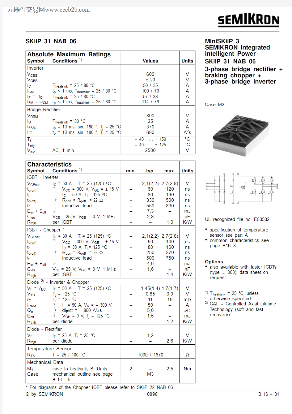
SKiiP 31 NAB 06
MiniSKiiP 3
SEMIKRON integrated intelligent Power SKiiP 31 NAB 06
3-phase bridge rectifier +braking chopper +
3-phase bridge inverter
Case M3
UL recognized file no. E63532
?specification of temperature sensor see part A
?
common characteristics see page B16–3
Options
?also available with faster IGBTs (type ... 063), data sheet on request
1)T heatsink = 25 °C, unless otherwise specified
2)
CAL = Controlled Axial Lifetime Technology (soft and fast recovery)
* For diagrams of the Chopper IGBT please refer to SKiiP 22 NAB 06
B 16 – 32
0698
? by SEMIKRON
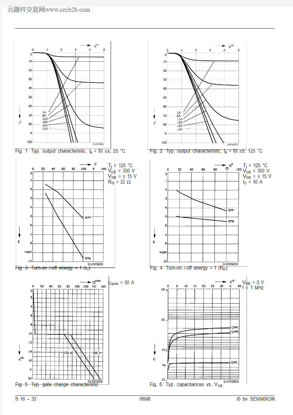
Fig. 3Turn-on /-off energy = f (I C )
Fig. 4Turn-on /-off energy = f (R G )
T j = 125 °C V CE = 300 V V GE = ± 15 V I C = 50 A
T j = 125 °C V CE = 300 V V GE = ± 15 V R G = 22 ?
I Cpuls = 50 A
V GE = 0 V f = 1 MHz
Fig. 1Typ. output characteristic, t p = 80 μs; 25 °C
Fig. 2Typ. output characteristic, t p = 80 μs; 125 °C
Fig. 5Typ. gate charge characteristic Fig. 6Typ. capacitances vs. V CE
? by SEMIKRON
0698
B 16 – 3
Fig. 9Turn-off safe operating area (RBSOA) of the IGBT Fig. 10Safe operating area at short circuit of the IGBT
T j
= ≤ 150 °C V GE = ± 15 V t sc = ≤ 10 μs L ext < 25 nH
T j = ≤ 150 °C V GE = ± 15 V
Fig. 7Rated current of the IGBT I Cop / I C = f (T h )
T j = 150 °C V GE = ≥ 15 V
00.2
0.4
0.6
0.8
1.0
1.2
25
50
75
100
125
150I Cop /I C Mini0607
T h [°C]
Fig. 11Typ. freewheeling diode forward characteristic Fig. 12Forward characteristic of the input bridge diode https://www.doczj.com/doc/65230477.html,mon characteristics of MiniSKiiP
MiniSKiiP 600 V
MiniSKiiP 3
SKiiP 30 NAB 06 SKiiP 31 NAB 06 SKiiP 32 NAB 06 SKiiP 30 NAB 12 SKiiP 31 NAB 12 SKiiP 32 NAB 12Circuit
Case M3
Layout and connections for the
customer’s printed circuit board