Fracture Analysis at a Stress Point
Problem Description
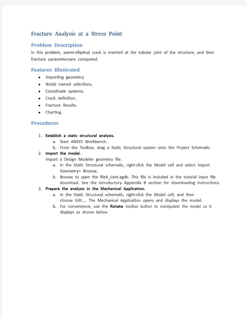
In this problem, asemi-elliptical crack is inserted at the tubular joint of the structure, and then fracture parametersare computed.
Features Illustrated
?Importing geometry
?Nodal named selections.
?Coordinate systems.
?Crack definition.
?Fracture Results.
?Charting.
Procedures
1.Establish a static structural analysis.
a.Start ANSYS Workbench.
b.From the Toolbox, drag a Static Structural system onto the Project Schemati
c.
2.Import the model.
Import a Design Modeler geometry file.
a.In the Static Structural schematic, right-click the Model cell and select Import
Geometry> Browse.
b.Browse to open the fileX_Joint.agdb. This file is included in the tutorial input file
download. See the introductory Appendix B section for downloading instructions.
3.Prepare the analysis in the Mechanical Application.
a.In the Static Structural schematic, right-click the Model cell, and then
choose Edit.... The Mechanical Application opens and displays the model.
b.For convenience, use the Rotate toolbar button to manipulate the model so it
displays as shown below.
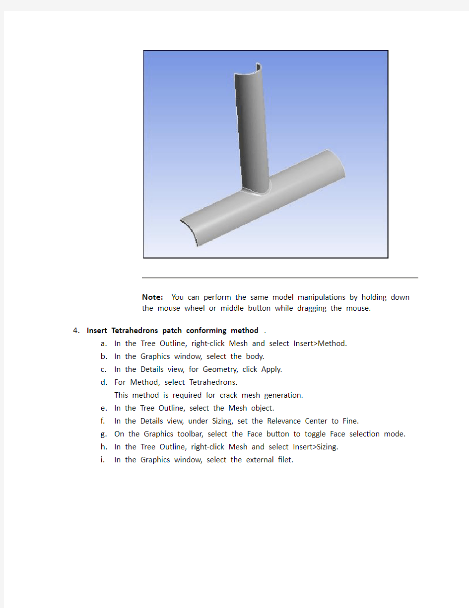
4.Insert Tetrahedrons patch conforming method.
a.In the Tree Outline, right-click Mesh and select Insert>Method.
b.In the Graphics window, select the body.
c.In the Details view, for Geometry, click Apply.
d.For Method, select Tetrahedrons.
This method is required for crack mesh generation.
e.In the Tree Outline, select the Mesh object.
f.In the Details view, under Sizing, set the Relevance Center to Fine.
g.On the Graphics toolbar, select the Face button to toggle Face selection mode.
h.In the Tree Outline, right-click Mesh and select Insert>Sizing.
i.In the Graphics window, select the external filet.
j.In the Details view, for Geometry, click Apply.
k.For Element Size, enter 5e-3 m.
l.Right-click the Mesh object and select Generate Mesh.
5.Create coordinate system.
a.In the Tree Outline, select Coordinate Systems.
b.Right-click and select Insert>Coordinate System, or from the Environment
Context toolbar, select Coordinate Systems> Coordinate System.
c.In the Graphics window, select the vertex lying at the center of the filet face.
d.In the Details view, for Geometry, click Apply.
e.Then for the Primary Axis, select X axis and modify the Define By property to Hit
Point Normal.
f.In the Graphics window, click at the origin location of the coordinate system.
g.In the Details view, for Hit Point Normal, click Apply.
h.From the Environment Context toolbar, select Coordinate Systems> Flip X to
make X axis looks inwards the structure.
6.Define the crack.
a.Select the Model object in the Tree Outline.
b.Insert a Fracture object into the Tree by right-clicking the Model object and
selecting Insert > Fracture.
c.Insert a Crack object into the Tree by right-clicking the Fracture object and
selecting Insert > Crack.
d.On the Graphics toolbar, select the Body button to toggle Body selection mod
e.
e.In the Graphics window, select the body.
f.In the Details view, for Geometry, click Apply.
g.For Coordinate System, select the coordinate system previouslycreated.
h.In addition, set the following options in the Details view:
i.In the Tree Outline, right-click the Fractureobject and select Generate All Crack
Meshes.
j.Zoom in on the external filet to see the generated crack mesh.
6.Apply loads.
a.From the main menu, choose Units> Metric (mm, kg, N, s, mV, mA).
b.In the Tree Outline, select Static Structural.
c.Right-click and select Insert>Pressure, or from the Environment Context toolbar,
select Loads > Pressure.
d.In the Graphics window, select the top fac
e.
e.In the Details view, for Geometry, click Apply.
f.For Magnitude, enter -1000 MPa.
The negative value indicates the pressure direction is upward.
7.Solve.
a.In the Tree Outline, under Static Structure, select Analysis Settings.
b.Under Solver Controls, set Fracture to On.
c.Click Solve.
8.Define Stress Intensity Factor results.
a.In the Tree Outline, right-click on Solution and select Insert > Fracture Tool.
b.In the Details view, for Crack Selection, select Crack.
c.Right-click the Fracture Tool folder and select SIFS Results>SIFS (K2), or select the
Fracture Tool folder and, from the Fracture Tool toolbar, select SIFS Results >SIFS
(K2).
d.Also add the SIFS (K3) result.
e.In the Tree Outline, right-click the Fracture Tool object and select Evaluate All
Results.
9.View results.
a.Select each result and view the results in the Graphics window.
b.View the Graph window for each result. The graph plots the stress intensity
factors against the curvilinear abscissa of the crack front, starting from the origin
extremity.
Since the crack surface normal is nearly aligned with the tensile load, the Mode I
stress intensity factor ((SIFS [K1]) dominates in this case. The SIFS (K2) and SIFS
(K3) results show that ModeII and Mode III slightly contribute.