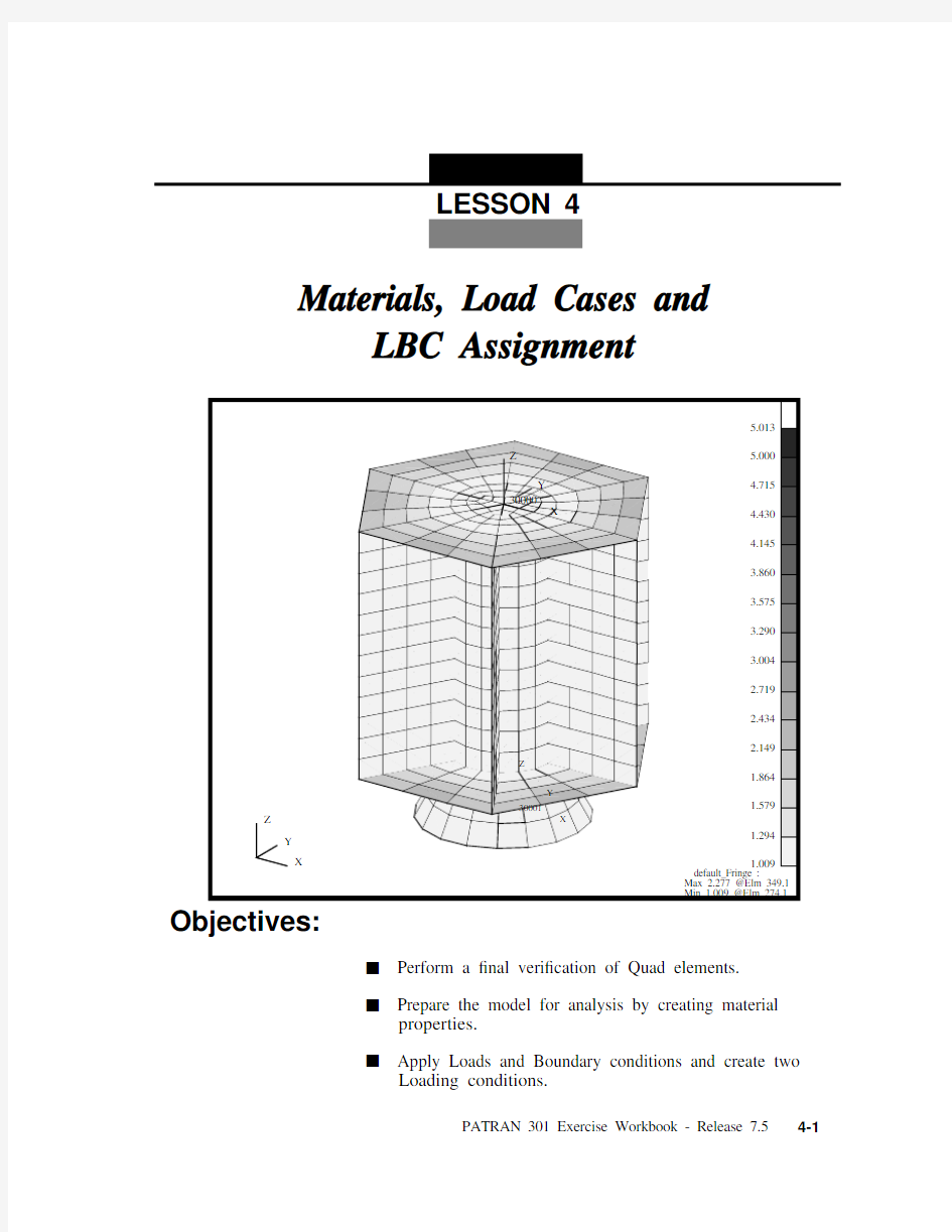

Materials, Load Cases and
LBC Assignment
X
Y Z
Y
30001
Z
X
Y 30000
Z
X
5.013
5.0004.7154.4304.1453.8603.5753.2903.0042.7192.4342.149
1.864
1.579
1.294
1.009
default_Fringe :
Max 2.277 @Elm 349.1Min 1.009 @Elm 274.1
LESSON 4
Objectives:
s Perform a ?nal veri?cation of Quad elements.s Prepare the model for analysis by creating material
properties.s Apply Loads and Boundary conditions and create two
Loading conditions.
LESSON 4
Materials, Load Cases and LBC Assignment
Model Description:
This exercise continues to prepare the Satellite model for analysis.You will check the Quad elements aspect ratio and de?ne element and material properties. Finally, you will assign Loads and Boundary conditions to the model and set up two Loading conditions, one for Modal analysis and one for Static analysis.
Suggested Exercise Steps:
s Start MSC?PATRAN and open the satelite.db ?le.s Verify the Quad element’s aspect ratio using a threshold
value of 5.0.s Create an Isotropic material, named titanium , which uses a
Linear Elastic Constitutive Model. The material’s Elastic Modulus, Poisson’s Ratio and Density are 16E6, 0.16 and 0.27, respectively.s Create an Isotropic material, named aluminum , which uses
a Linear Elastic Constitutive Model. The material’s Elastic Modulus, Poisson’s Ratio and Density are 10.5E6, 0.33 and 0.101, respectively.s Create a simply supported displacement constraint, named
Launch constraint , for all vertices on the outside edges of the Upper and Lower Platforms (i.e., ball joint). The displacement will be ?xed in translation and free in rotation.s De?ne 3 inertial loadings according to the table below.
s Using Load Case, create two Load cases with the following
Load Name Trans. Accel.Direction Analysis
Coordinate System
Launch 1g + X <386.4, 0, 0>Coord 20000Launch 1g + Y <0, 386.4, 0>Coord 20000Launch 1g + Z
<0, 0, 386.4>
Coord 20000
properties.
s Close and Exit MSC/PATRAN.
Load Case Name LBC Scale Factor
Loads & Boundary
Conditions
Launch Modal LC 1.0launch constraint Launch Static LC
1.02.02.0-10.0
launch constraint Launch 1g + X Launch 1g + Y Launch 1g + Z
LESSON 4
Materials, Load Cases and LBC Assignment
Exercise Procedure:
Note: In most MSC?PATRAN forms, the default setting for the Auto Execute button is on; thus,you do not need to press Apply.1.
Start MSC?PATRAN and open the satelite.db ?le.
2.
Before we get started, let’s post the All Fem group and set the render style and orientation.
Change the model view and render style using the following Toolbar icons.
File/Open...
Existing Database Name satelite.db
OK Group/Post...Select Groups to Post
Adapter All Geometry Central Cylinder Lower Platform
Navigational Platform Propulsion Block Science Platforms Shear Panels Upper Platform default_group
Apply Cancel
Isometric View 3
Shaded Smooth
Open the Satellite Database
All Fem
Your model should be similar to the display below.
3.
Verify the Quad element’s aspect ratio using a threshold value of 5.0.Finite Elements
Action:Verify Object:Quad Test:Aspect Aspect Ratio
5.0
OK
Y
30001
Z
X
Y
30000
Z
X
X
Y Z
Figure 4.1. All Fem displayed for the Satellite
Aspect Ratio Veri?cation
LESSON 4
Materials, Load Cases and LBC Assignment
This will color code the Quad4 elements based on their aspect ratio values. Any element with an aspect ratio greater than or equal to your threshold value, 5.0, will be colored red according to the default spectrum.
A summary of the minimum and maximum aspect ratio for the elements is located in the lower right hand corner of the viewport.Reset Graphics
X
Y Z
Y
30001
Z
X
Y 30000
Z
X
5.019
5.0004.7154.4304.1453.8603.5753.2903.0042.7192.4342.149
1.864
1.579
1.294
1.009
default_Fringe:
Max 2.277 @Elm 349.1Min 1.009 @Elm 274.1
Figure 4.2.The Quad4 Aspect Ratio Veri?cation Plot.
4.
Create an Isotropic material, named titanium . The material’s Elastic Modulus, Poisson’s Ratio and Density are 16E6, 0.27 and 0.16, respectively.You will know the model has been created when the Current Constitutive Model list is updated. Now, let’s create a second material, named aluminum .The material’s Elastic Modulus,Poisson’s Ratio and Density are 10.5E6, 0.33 and 0.101,respectively.Again, you will know the model has been created when the Current Constitutive Model list is updated.Materials
Action:Create Object:Isotropic Method:Manual Input Material Name titanium
Input Properties...Constitutive Model:Linear Elastic Elastic Modulus =16E6Poisson Ratio =0.27Density =0.16
Apply Cancel
Material Name aluminum
Input Properties...Constitutive Model:Linear Elastic Elastic Modulus =10.5E6Poisson Ratio =0.33Density =0.101Apply
Cancel
Create Titanium &Aluminum Material Properties
LESSON 4
Materials, Load Cases and LBC Assignment
5.
Let’s create all the Loads and Boundary Conditions that will be needed to model a launch condition for the Satellite. We will start by de?ning the Launch constraints.
When one group is posted, MSC/PATRAN assumes that group is the current group. However, when more than one group is posted, MSC/PATRAN will require you to de?ne a current group. The current group is used to collect any new entities created. In this step, we will not be de?ning any new geometry or ?nite elements. We will select the Lower Platform as the current group.Change the view and render style of the model using the Toolbar icons.
Current Group Selection
Adapter All Fem
All Geometry Central Cylinder Navigational Platform Propulsion Block Science Platforms Shear Panels Upper Platform default_group
OK
Isometric View 3Wireframe
De?ne the Launch Constraints
Lower Platform
Finally, your model should now look like the ?gure below
Define the Launch constraints for the Satellite.Loads/BCs Action:Create Object:Displacement Type:Nodal New Set Name Launch constraint
Input Data...
Translations
Select Application Region...Geometry Filter
FEM 30000
X
Y
Z
20000
X
Y
Z
X
Y Z
Nodes to Constrain for Launch condition
Figure 4.3. Constraints for satellite on Upper and Lower Platform.
LESSON 4
Materials, Load Cases and LBC Assignment
Your model should now look like the figure shown
Select Nodes
Select nodes shown in Figure 4.3
Note: You need to hold the Shift key down to pick all the nodes at the same time.
Add OK Apply
123
123
123
123
123
123
123
123
123
123
123
123
30000
X
Y
Z
20000
Z
X
Y Z
Figure https://www.doczj.com/doc/488568130.html,unch Constraints applied to the satellite.
X
Y
6.
We will create an inertial loading due to the launch accelerations. We will de?ne three separate loadings, a Unit g load in the X, Y and Z directions. In a later step, we will use the created subcases that are scaled multiples of these loadings.
We will de?ne 3 inertial loadings as shown in the table below. It should be noted, the gravity constant for this problem is 1g = 386.4.We will start by creating a unit g load in the X-direction. The inertial loading is applied to the entire model. Since only one possible Application Region (All Finite Elements), there is no need to de?ne it.Repeat the above step for the Y and Z directions according to the table above. Make sure to update the New Set Name and Translation Acceleration Vector.
7.Finally, we will de?ne two Load Cases for this model. One Load Case contains only the Launch constraints and will be use for Modal analysis. Another Load Case contains the Launch
constraints and a combined set of inertial loadings. This Load Case will use for Static analysis.
Load Name Trans. Accel. Direction Launch 1g + X <386.4, 0, 0>Launch 1g + Y <0, 386.4, 0>Launch 1g + Z
<0, 0, 386.4>
Action:Create Object:Inertial Load Type:Element Uniform New Set Name Launch 1g + X
Input Data...
Trans Accel
De?ne the Launch
Acceleration
De?ne Two Load Cases
LESSON 4
Materials, Load Cases and LBC Assignment
We will make use of the capability of scaling the LBC’s. We will create the following load combination, where the gravitational vector is defined as <2, 2, -10 >. If we were making several load cases based on accelerations, this procedure would be very handy.We will start by defining the Modal Load case which will be used to determine the modal frequencies of the spacecraft in a launch configuration.
The Displacement Launch Condition should now have been added to your spreadsheet.Let’s create the second Load case to model a <2, 2, -10>G static loading condition.Load Case Name LBC Scale Factor
Loads & Boundary
Conditions
Launch Modal LC 1.0Launch Constraint Launch Static LC
1.02.02.0-10.0
Launch Constraint Launch 1g + X Launch 1g + Y Launch 1g + Z
Load Cases Action:Create Load Case Name Launch Modal Load Case Type:
Static
Assign/Prioritize Loads/BCs Selection Multiplier 1.0
Select Loads/BCs to Add to Spreadsheet
Displ_Launch constraint OK Apply
Load Case Name Launch Static Load Case Type:
Static
Assign/Prioritize Loads/BCs
The spreadsheet should already have the Launch constraint selected.We will now de?ne the 3 inertial loadings.The spreadsheet should now show the 3 inertial loading conditions along with the displacement constraint. Additionally, the spreadsheet also indicates the LBC scale factor.8.To complete this exercise, you will close the database.
This will exit MSC/PATRAN and close your ?le. Do not delete the database from your directory since you will use it for future exercises.
Selection Multiplier 2.0
Select Loads/BCs to Add to Spreadsheet Inert_Launch 1g + X Selection Multiplier 2.0
Select Loads/BCs to Add to Spreadsheet Inert_Launch 1g + Y Selection Multiplier -10.0
Select Loads/BCs to Add to Spreadsheet
Inert_Launch 1g + Z
OK Apply
File/Quit
Close the Database and Quit Patran