A75W Real-Time Scalable Body Area Network Controller and a25W ExG Sensor IC for Compact Sleep Monitoring Applications
Seulki Lee,Student Member,IEEE,Long Yan,Member,IEEE,Taehwan Roh,Student Member,IEEE, Sunjoo Hong,Student Member,IEEE,and Hoi-Jun Yoo,Fellow,IEEE
Abstract—A light-weighted body area network using3-layer coin-sized fabric patches is proposed for sleep monitoring systems. It consists of two ICs,a network controller(NC)and a sensor node (SN),and also Wearable Band(W-Band)to connect them.The Continuous Data Transmission(CDT)protocol is proposed for low power and real-time scalability by in-order data transmission using W-Band among several sensors.Based on this protocol, Linked List based network Manager(LLM)and Adaptive Dual Mode Controller(ADMC)in NC,and low swing data transmitter (D-TX)and its own back-end circuits are introduced.The LLM and ADMC can adaptively change the network con?guration ac-cording to the dynamic network variances in real-time(500ms), and D-TX can make low energy data transmitter of0.33pJ/b with20Mbps data rate for W-Band interface.These two low power ICs,which are implemented in0.18m CMOS process and operates with1.5V supply,consume75W and25W, respectively.
Index Terms—Home sleep monitoring system,low power, polysomnography,wearable body area network,wearable elec-tronics.
I.I NTRODUCTION
P EOPLE generally spend almost1/3of their lifetime for sleep.Since good sleep is indispensable to the better quality of human life,it has been regarded as one of the important factors for the healthy life in these days[1].But many people sometimes experience a sleep disorder,which is a medical disorder of the sleep patterns such as sleep apnea, insomnia,narcolepsy,sleepwalking,and so on.Currently,over 40million American suffer from chronic sleep disorders,and more than100thousand motor vehicle accidents result from them annually[2],[3].Also,its cost has been increased every year so that it amounts to50billion dollars in USA in2010 [4].For effective and primary care for these sleep disorders,its recognition and diagnosis are particularly important.So,several sleep monitoring systems have been developed as a diagnostic
Manuscript received May05,2011;revised July15,2011;accepted September13,2011.Date of publication November04,2011;date of current version December23,2011.This paper was approved by Guest Editor Satoshi Shigematsu.
S.Lee,T.Roh,S.Hong,and H.-J.Yoo are with the Department of Electrical Engineering,Korea Advanced Institute of Science and Technology(KAIST), Daejeon305-701,Korea(e-mail:sklee@eeinfo.kaist.ac.kr).
L.Yan was with KAIST,Daejeon305-701,Korea,and is now with IMEC, B-3001Leuven,Belgium.
Color versions of one or more of the?gures in this paper are available online at https://www.doczj.com/doc/488211990.html,.
Digital Object Identi?er10.1109/JSSC.2011.2170636tool for polysomnography,which is a multi-parametric test used in a sleep study[5]–[7].In these systems,several bio-sig-nals like electrocardiography(ECG),electroencephalography (EEG),electromyography(EMG),and electrooculography (EOG)are recorded from sensors attached to the human body, and it is followed by data collection,management,and storage in a controller.Although the system should be comfortable with fewer wires,lighter weight,and smaller size in order not to disturb the user’s sleep,previous systems not only have huge and heavy form factors,but also consume large power leading to the use of a big battery[5],[6].Moreover,a person will frequently turn over on his/her side while sleeping so that the devices on the body unintentionally slip off.It signi?cantly reduces the system reliability and increases the redundant power consumption because the user cannot repair the broken devices during sleep.But none of the previous systems has considered this problem yet.
Therefore,we propose a compact and intelligent sleep mon-itoring system using a real-time scalable network controller IC and low-power sensor ICs with the help of the Planar Fashion-able Circuit Board(P-FCB)technique[8].The proposed system consists of a Network Controller(NC)patch with the controller IC and Sensor Node(SN)patches with the ExG sensor IC, and they are connected to each other through Wearable Band (W-Band).In the controller IC,the Linked-List based network Manager(LLM)is adopted to achieve real-time(500ms)net-work scalability even under dynamic movement of human body during sleep.The Adaptive Dual-Mode Controller(ADMC)is proposed for low-power controller IC75W.Also,the low swing data transmitter(D-TX)and its own back-end circuits ac-cording to the Continuous Data Transmission(CDT)protocol are proposed for the W-Band interface so that the average en-ergy dissipation of data transmission becomes0.33pJ/b,while each sensor IC consuming below25W in average.With the help of two ICs,the proposed system with1NC and14SN patches consumes only425W so that it can operate with one small coin battery for over10hours sleep.
The rest of the paper is organized as follows.In Section II, the proposed sleep monitoring system with NC,SN patches and W-Band will be overviewed.Section III explains the CDT pro-tocol.The network controller IC and its two schemes,named LLM and ADMC,and the sensor IC with D-TX,the trans-ceiver back-end and sensor front-end circuits will be covered in Sections IV and V,respectively.Then,the implementation results will be shown in Section VI.Finally,conclusions will be made in Section VII.
0018-9200/$26.00?2011IEEE
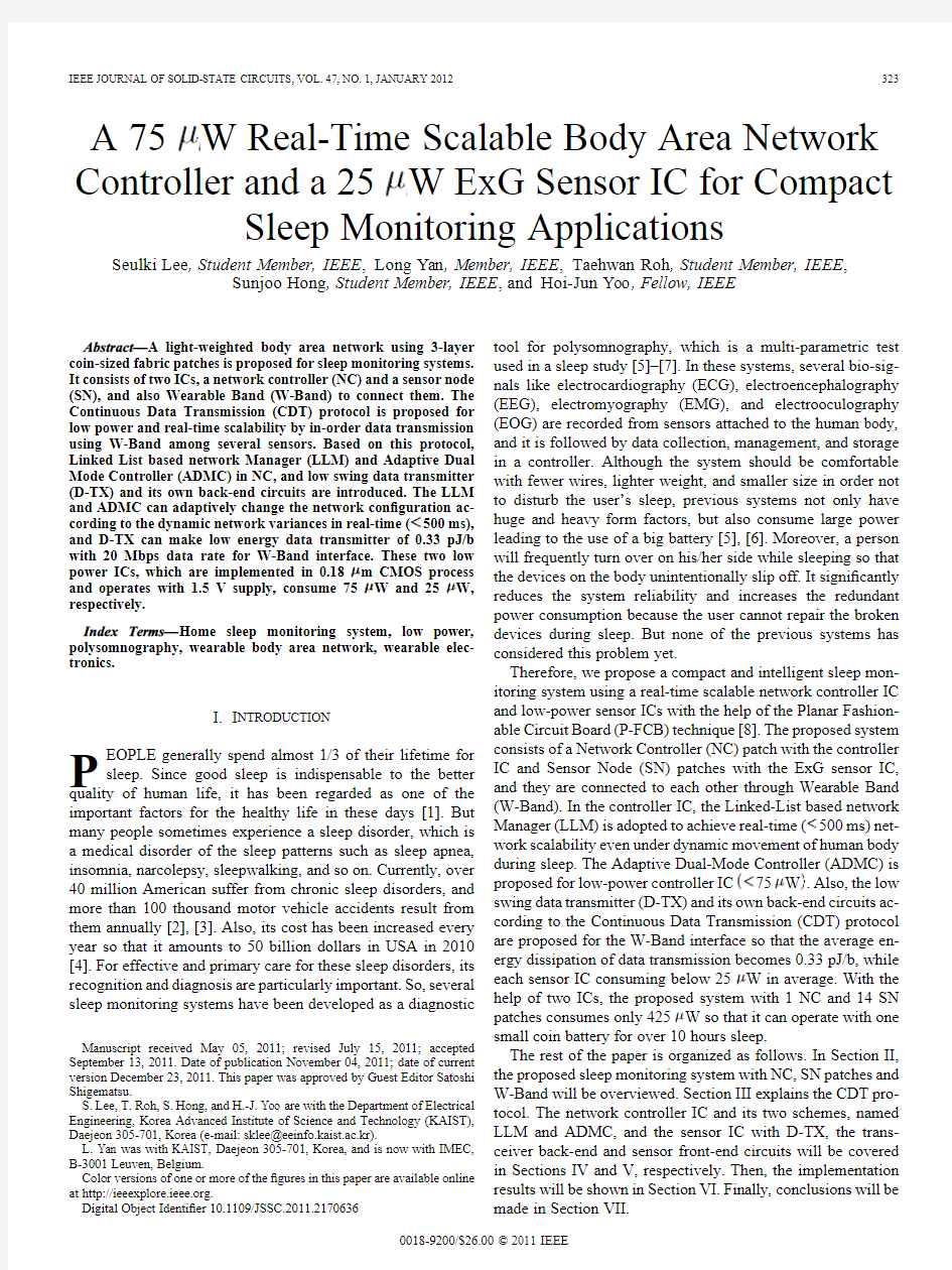
Fig.1.The proposed sleep monitoring
system.
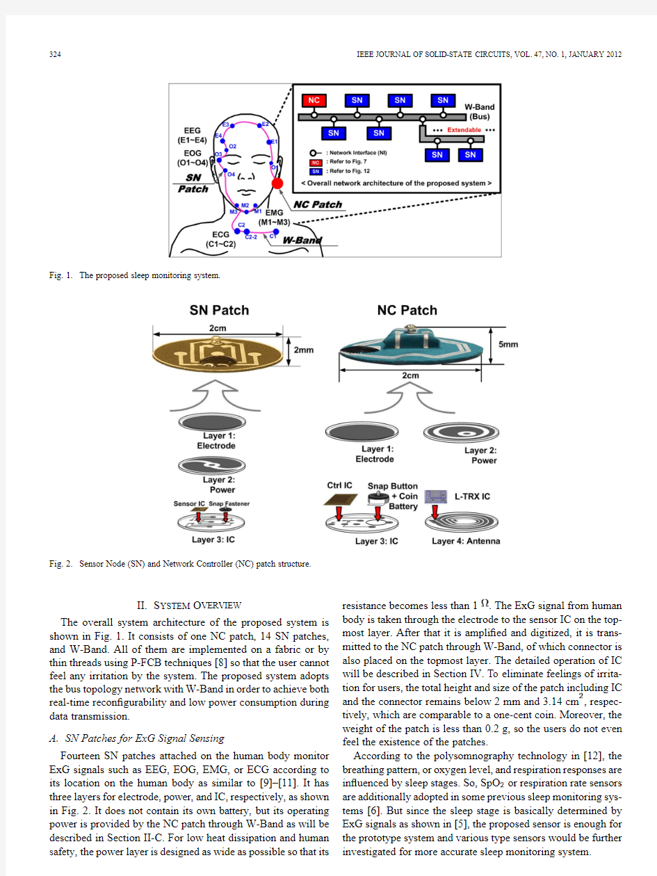
Fig.2.Sensor Node (SN)and Network Controller (NC)patch structure.
II.S YSTEM O VERVIEW
The overall system architecture of the proposed system is shown in Fig.1.It consists of one NC patch,14SN patches,and W-Band.All of them are implemented on a fabric or by thin threads using P-FCB techniques [8]so that the user cannot feel any irritation by the system.The proposed system adopts the bus topology network with W-Band in order to achieve both real-time recon ?gurability and low power consumption during data transmission.
A.SN Patches for ExG Signal Sensing
Fourteen SN patches attached on the human body monitor ExG signals such as EEG,EOG,EMG,or ECG according to its location on the human body as similar to [9]–[11].It has three layers for electrode,power,and IC,respectively,as shown in Fig.2.It does not contain its own battery,but its operating power is provided by the NC patch through W-Band as will be described in Section II-C.For low heat dissipation and human safety,the power layer is designed as wide as possible so that its resistance becomes less than 1.The ExG signal from human body is taken through the electrode to the sensor IC on the top-most layer.After that it is ampli ?ed and digitized,it is trans-mitted to the NC patch through W-Band,of which connector is also placed on the topmost layer.The detailed operation of IC will be described in Section IV.To eliminate feelings of irrita-tion for users,the total height and size of the patch including IC and the connector remains below 2mm and 3.14cm ,respec-tively,which are comparable to a one-cent coin.Moreover,the weight of the patch is less than 0.2g,so the users do not even feel the existence of the patches.
According to the polysomnography technology in [12],the breathing pattern,or oxygen level,and respiration responses are in ?uenced by sleep stages.So,SpO or respiration rate sensors are additionally adopted in some previous sleep monitoring sys-tems [6].But since the sleep stage is basically determined by ExG signals as shown in [5],the proposed sensor is enough for the prototype system and various type sensors would be further investigated for more accurate sleep monitoring system.
LEE et al.:A75W REAL-TIME SCALABLE BODY AREA NETWORK CONTROLLER AND A25W ExG SENSOR IC325
B.NC Patch for Network Control
The NC patch of the proposed system is also shown in Fig.2. It has four layers of the electrode,power,IC,and antenna.Since the electrode of the NC patch acts as a reference for ExG signals, it is placed behind the ear where there are no muscles but only bones,so that EMG noise is suppressed.The battery on the third layer is the only power source of the total system,and its size is only5.8mm(diameter) 2.1mm(height)with0.2g weight (LR63,alkaline,10mAh).The controller IC and the connector are also integrated into the third layer.The ExG signals from all SN patches through W-Band are collected,managed,and tem-porary stored in this IC.They are also locally processed with the dedicated?lter and compressor blocks[13].If the memory be-comes full,it transmits the data to the external station using near-?eld communication by the inductive coupling(L-TRX)IC and fabric antenna in the fourth layer[14].After the local compres-sion in the controller IC with the ratio of1:8,the total data size becomes less than4KB per seconds.With an internal memory of10KB,the data should be transmitted at least every2.5sec-onds to avoid the memory over?ow.Thanks to high speed and low energy near-?eld communication,its transmission time and power is not overhead for battery-operated systems[14].
C.Wearable Band(W-Band)
W-Band is adopted to connect NC patch and all SN patches, and it has?ve sub-lines to operate all SNs properly.As described in the previous sections,1)the operating power line and2)the ground line should be shared by them,and3)the reference line for the ExG signal sensing is also connected between them. Lastly,4)the clock line and5)the data line sends and receives the command and data between NC and SN patches according to the CDT protocol which will be explained in Section III.Therefore, W-Band contains?ve sub-lines as shown in Fig.3.Since each of them should be electrically shielded to prevent electrical short, each sub-line is made by the coated conductive yarn,and all of them are merged again using non-conductive fabric[11].To interface with NC and SN patches,the metal snap button con-nectors are used.Fig.3also shows the magni?ed diagram of the connectors.In both NC and SN patches,the female connectors are placed,and the male connectors are integrated into W-Band. When the patches are connected to W-Band,a pair of the snap button is served as the electrical connection for one sub-line (sub-line#1in Fig.3)and remaining connections for4sub-lines are implemented around the snap button using P-FCB.Because of the circular shape of the snap button which is symmetric in all directions,there is a tiny bump on it in order to attach the correct pair of connections.Since the conductive yarn has as low resis-tance as normal wires and enough bandwidth over20MHz,data transmission through W-Band is just like the common wire-line communication,consuming very small power compared to the other wireless/near-?eld communications[10],[15].Since the sensing locations for sleep monitoring are restricted to the human face and additionally only to a chest,not to a whole body,the wired BAN is quite suitable without any disturbance.Moreover, the possible detachment or breakdown of the sensors during sleep can be treated by the real-time scalable network controller IC which will be described in Section
IV.Fig.3.Wearable band
(W-band).
Fig.4.System operation?ow.
D.System Operation Flow
The system operation?ow of the proposed sleep monitoring system is shown in Fig.4.Before sleeping,the patches are at-tached to the human face and chest,where the target ExG sig-nals can be properly obtained.For EEG signals,it should be at-tached to the forehead and head,and for EOG signals,it should be placed up,down,right,and the left of the eyes.Three sensors are needed on the jaw to monitor the EMG signal of mentalis and submentalis muscles,and?nally,ECG signals can be detected on the chest.And then,W-Band connects the patches starting from NC patch.When each SN patch is connected to W-Band, they are turned on by the battery in NC patch.Then,it joins to the network and starts its operation.During sleep,the controller IC monitors whether every SN patch is well operating or not. And if it discovers malfunction of a SN patch,the controller IC adaptively turns it off and turns the other redundant or back-up sensors on.The transmitted and stored data to the external sta-tion can be checked after wake-up.
III.C ONTINUOUS D ATA T RANSMISSION(CDT)P ROTOCOL The proposed system adopts the new communication pro-tocol named Continuous Data Transmission(CDT)protocol for low power consumption and better to recognize the network status change such as join and leave.Before describing the pro-posed protocol,two operation modes of the proposed system should be de?ned;one is Sensing Only(SO)mode and the other is Sensing and Communication(SC)mode.The characteristics
326IEEE JOURNAL OF SOLID-STATE CIRCUITS,VOL.47,NO.1,JANUARY 2012
TABLE I
T WO O PERATION M ODES OF THE P ROPOSED S
YSTEM
Fig.5.Continuous Data Transmission (CDT)protocol.
of each mode are summarized in Table I.In SO mode,each SN operates with only 20KHz clock which is transmitted from NC through W-Band.Since there is no data transmission from SN in this mode,other blocks than a clock generator and transmitter of ADMC are sleeping for low power consumption in NC.Also,only sensor front-end circuits for ExG monitoring and the re-ceiver for clock and command are activated in all SNs.On the other hand,the data is transmitted and received in SC mode with 20MHz clock which is also transmitted from NC.All blocks in both NC and SN are activated so that ExG sensing and data transaction are performed at once.Due to the higher frequency clock transmission and full operation of all blocks,the average power consumption of SC mode,1.866mW,is much higher than SO mode,364.8W.
The proposed CDT protocol de ?nes the data communication operation in SC mode as shown in Fig.5.First,as soon as the operation mode is changed to the SC mode,the data communi-cation starts.The NC sends the data request command to the ?rst SN,but since the communication channel of W-Band is shared by all SNs,it is also used as an activator for the ID checker in other SNs.In the last part of the data from each SN,the post-amble includes the ID of the next SN as shown in Fig.6.So,the next SN can send its data without the command from NC.And the postamble of the last SN has also the role of invitation
for
Fig.6.Proposed packet structure.
the new SN to join.Since the data communication is performed in every 10ms in worst case,it is assumed that the new SN can be activated at most one per 10ms theoretically if the user can attach the nodes as quickly as possible.During the operation,if a SN leaves from the network,the data is saturated to rail-to-rail values so that leave detector in LLM can recognize it.In order to make sure the SN is really detached from the network,LLM waits for 500ms,or 1024cycles,of abnormal data as will be described in Section IV.
IV .R EAL -T IME S CALABLE B ODY A REA N ETWORK
C ONTROLLER IC The overall architecture of the proposed network controller IC is shown in Fig.7.It consists of LLM,ADMC,several blocks for local processing like a compressor,a ?lter,an internal memory,and a RISC,and a Network Interface (NI)with the clock transmitter (C-TX),data transceiver (D-TX and D-RX),and its back-end circuits.Among these blocks,the LLM and ADMC are newly proposed in this work for dynamically scalable network and its low power management,respectively.During operation,LLM can control the dynamic change of the network in real-time.In other words,it can detect the network status such as leave and join of the nodes during data communication,and insert or delete it quickly.Also,ADMC can control the operation modes of the whole system adaptively so that the average power consumption is reduced.A.Linked-List Based Network Manager (LLM)
The block diagram of the proposed LLM is shown in Fig.8.It adopts a dual linked list structure for easy addition and re-moval of the nodes in the network.Since SN patches on the human body could be unintentionally distorted during sleep and it should be compensated in order to achieve more reliability,dynamic operations such as join and leave are essential for ef ?-cient network management.Moreover,since the time when the distortion occurs is unknown to users,the intelligent detection and control are also required.In the proposed LLM,the leave and join detector are integrated in order to recognize the change of network status simultaneously with the received data stream
,and modify it as soon as the change is detected.
Fig.9(a)shows the principle and the block diagram of the leave detector.In the proposed system,the data transmission order is determined by the ID of the SN patch according to CDT protocol.If the data is saturated over the dynamic range
LEE et al.:A 75W REAL-TIME SCALABLE BODY AREA NETWORK CONTROLLER AND A 25W ExG SENSOR IC
327
Fig.7.Overall architecture of the proposed network controller
IC.
Fig.8.Linked-List based network Manager (LLM).
for more than 1024sequential cycles in the speci ?c order,the leave detector set the leave ?ag,which means the corresponding SN patch is detached from the network.As shown in Fig.9(a),it is implemented by the comparator and counters as many as the number of SN patches in the network.To reduce power con-sumption,the counter operates if and only if the ID is matched.Otherwise,it is not activated by clock gating.By using this leave detector,network leave of the SN can be detected within 500ms while the sampling rate is 2Ksamples/s.The join detector is shown in Fig.9(b).If there is no join request packet after the data from the last SN,the operation mode immediately becomes SO mode and all SNs continuously monitor the user’s ExG signal.But if there is,it is regarded as the network join and the linked list controller adds it to the list ?rst.When the network join or leave ?ags are set,the linked list controller adds,removes,or modi ?es each node in the network.Since the system adopts the dual-linked list structure to make all connections possible to be recovered in network leave cases,both pre-node and post-node should be modi ?ed by the join and leave ?ag.Especially,the new node is added as the post node of the last node in the net-work join case.So,the post-node slot of the last node should be changed to the new node.And for the new node,its pre-node becomes the last node and the post-node slot is remained as “empty”.And then,the last node information of the linked list is updated as the new node.The network modi ?cation can be done in less than 8s with 20MHz clock in SC mode so that the ExG sensing even with maximum sampling period of 500s (2Ksamples/s)is not affected at all by this process.
328IEEE JOURNAL OF SOLID-STATE CIRCUITS,VOL.47,NO.1,JANUARY
2012
Fig.9.(a)Leave detector in LLM;(b)join detector in LLM.
B.Adaptive Dual-Mode Controller(ADMC)
When ADMC determines the system operation mode,it adopts the command-based mode control in order to change the operation mode adaptively to the number of SNs in the network. Since the power consumption of SC mode is much higher than SO mode,the SC mode duration should be decreased as short as possible for low power system.After one SN leaves from the network,the required SC mode duration is reduced.Otherwise, if one SN joins to the network,the required SC mode duration is increased.But in the previous network controller,the mode du-ration is?xed and controlled in given time[5],or it should be set one-by-one for all SNs in every communications[15].With the time-based controller,it consumes redundant power until each SN responds even in the leaving case since the controller does not know when the SN sends the data during the allocated time slot.If the number of SNs decreases due to the network leave, the redundant power consumption becomes even higher because the time-based controller waits for the data from the leaving node.It was necessary in wireless network,but no more needed in the wire-line network like the proposed system.And with the centralized time slotting as in[15],the network leave could be re?ected individually but the communication overhead due to the every time slotting allocated to each SN is quite large resulting in also huge power consumption.In the proposed ADMC,both drawbacks of redundant power consumption and communication overhead are solved by the command-based mode control,which uses the last SN information that is updated by LLM in real time. Fig.10shows the operation of the ADMC in the point of view from both NC and SN.When the ID of the last node is detected and there is no join request packet,then ADMC broadcasts the 10-bit mode change command to the network from SC mode to SO mode with20Mbps data rate.And during SO mode,the timer is set for the next data transaction.At10clock cycles before the required mode changing time,or500s with20KHz clock,the ADMC starts to broadcast the10-bit mode change command from SO mode to SC mode with20Kbps data rate.So,the whole network can change their operation mode at the same time. Fig.11presents the reduction of the communication time,or SC mode duration,by the proposed ADMC and CDT compared with the previous systems[5],[15].In this comparison,the dual mode operation is assumed for all systems.Since ADMC can use the last node’s ID which is continuously updated by LLM, the redundant time and power consumption can be eliminated. Moreover,the dedicated command for mode change,which is broadcasted by ADMC,can remove the overhead for the time slotting command.As a result,26.8%of communication time can be saved with the proposed ADMC and https://www.doczj.com/doc/488211990.html,pared to the case without dual mode operation,the communication time is reduced by58%in the proposed schemes[7].
LEE et al.:A 75W REAL-TIME SCALABLE BODY AREA NETWORK CONTROLLER AND A 25W ExG SENSOR IC
329
Fig.10.Adaptive Dual Mode Controller (ADMC)
operation.
https://www.doczj.com/doc/488211990.html,munication time reduction by ADMC and CDT.
V .L OW -P OWER E X G S ENSOR IC
The overall architecture of the proposed ExG sensor IC is shown in Fig.12.It consists of the analog front-end circuit for ExG sensing,transceiver back end circuits and Network Inter-face (NI)with the clock receiver (C-RX)and data transceiver (D-TX and D-RX).In the transceiver back-end,there is a tem-poral memory for 20samples of 10-bit data so that ExG data can be transmitted at once which makes the transceiver con-sume low energy.The analog front-end circuits adopt the fully differential structure to achieve high SNR.A.Low Swing Data Transmitter (D-TX)
Fig.13(a)shows the proposed D-TX circuit in each SN.To reduce power consumption,its supply voltage is re-duced to 0.75V rather than 1.5V of other blocks.To make this supply voltage ef ?ciently,the output of C-RX is shared be-tween the voltage generator and the analog front-end circuits.The voltage generator is implemented as a switched-capacitor type dc-dc converter as shown in Fig.13(a).It can generate
the
Fig.12.Overall architecture of the proposed sensor IC.
half for only D-TX with less loss compared to other types of voltage converters.Since D-TX is activated in SC mode only,20MHz clock is used for 0.75V supply generation.The total capacitor for voltage generator,C1,is 100pF,and its conver-sion ef ?ciency is 78%with 100A load current.
The transceiver back-end circuit is the hardware mapping blocks of the CDT protocol in each SN as shown in Fig.13(b).It includes the local memory,a serializer,an ID comparator,a packet/depacketizer,and some control logic circuits.As men-tioned in Section III,these blocks are partially activated ac-cording to the operation mode of the system.Especially,there are three kinds of control signals for writing and reading the data to/from it,which are named ,,
330IEEE JOURNAL OF SOLID-STATE CIRCUITS,VOL.47,NO.1,JANUARY
2012
Fig.13.(a)Front-end circuits of the low swing Data Transmitter(D-TX);(b)transceiver back-end circuits with the hardware mapping of CDT protocol.
and for the low power serializer.During the SO mode,the data is temporally stored in the local memory,of which maximum capacity is20samples,at every edge of the EoC(End of Conversion)?ag from the ADC.And in SC mode, when the post ID of the current data packet is matched with its own ID,the SN enables the other blocks in back-end cir-cuits by using the dataREQ?ag and starts to make1-bit seri-alized data stream for20data samples.First,the20-bit con-trol signal moves the sampled data in the local memory to the corresponding slots of the serializer.Then,the 20-bit signal for each sample is enabled in order to load the data to the transmitter.At the same time,two con-trol signals,and,are continuously enabled among data samples as shown in Fig.13(b).The20 transistors with gating signal of are shared by10 bits of one sub-serializer,and another10transistors with gating signal of are shared by all20sets of sub-serial-izer.This shared structure makes the total transistor area and switching power consumption is reduced by61.7%and40%, respectively.After it sends the entire data in the local memory, all blocks of D-TX and back-end circuits are deactivated until the next SC mode starts.
The local memory depth for each SN is optimized as shown in Fig.14(a).If the local memory depth is low,data should be more often transmitted so that transmission power consumption is increased.Otherwise if the local memory depth is high,power consumption for data storage becomes dominant.As shown
in Fig.14.(a)Local memory depth optimization;(b)duty cycle reduction result. Fig.14(a),the optimal number of the local memory depth is be-tween10and20.Among them,the depth of20is chosen in this
LEE et al.:A75W REAL-TIME SCALABLE BODY AREA NETWORK CONTROLLER AND A25W ExG SENSOR IC
331
Fig.15.Analog front-end circuits.(a)Ampli?ers;(b)SAR ADC.
work in order to store the most samples for one time transmis-sion.It can increase the degree of freedom so that the transmis-sion error can also be handled.Fig.14(b)shows the duty cycle reduction results thanks to the proposed CDT protocol.With the ?xed maximum data rate of20Mbps,the ratio for SC mode du-ration becomes the smallest when the depth is20.In this case, 23.5%of duty cycle reduction can be obtained compared to the conventional protocol shown in[5],which results in the average power reduction of the system.
B.Analog Front-End
The analog front-end circuit includes the ampli?ers and 10-bit SAR ADC as shown in Fig.15(a)and(b),respectively. To amplify the small ExG signals from human body,two ca-pacitive feedback instrumentation ampli?ers are adopted both for low power consumption and intrinsically blocking the DC offsets from the wearable electrode by P-FCB.To deal with four different ExG signals of EMG,EOG,ECG,and EEG,the?rst ampli?er maximizes the power noise ef?ciency,and the second ampli?er provides programmable gain and bandwidth from 48.5dB to60dB and0.4–40Hz to0.4–300Hz,respectively. From the instrumentation ampli?ers to SAR ADC,the circuits are implemented in balanced architecture in order to achieve high common mode rejection over80dB.This AFE can provide total dynamic range of overall50dB which is supported by SAR ADC,performing effective number of bit is8.9bits.
VI.I MPLEMENTATION R ESULTS
Fig.16shows the chip micrograph of the proposed controller IC and sensor IC.The die size is2.45mm 2.6mm and 2.45mm 1.7mm for NC and SN,respectively,including pads in a0.18m CMOS technology.The successful leave detection and the ADMC operation is shown in Fig.17.The signal from the electrode becomes saturated if the electrode is detached from the skin.And if the time for saturation
lasts Fig.16.Chip micrograph.
TABLE II
P ERFORMANCE S
UMMARY
over1024cycles or500ms,the node is regarded as the leaving node,and LLM removes it from the network.Then,ADMC changes the mode duration adaptively so that the SC mode time is reduced after the electrode of one SN is detached.According to the operation mode determined by ADMC,data transaction between NC and SN is performed or slept.In the last10cycles of SO mode,the mode change command from NC is broad-casted to all SNs with20Kbps data rate as shown in Fig.18. After the mode is changed into SC mode,data transmission from each SN to NC is started.Low supply voltage of0.75V is generated by recovered clock of20MHz resulting in low power data transaction of the ExG signal.At the end of the data of the last SN,the mode is changed again into SO mode and it is repeated during user’s sleep.Fig.19shows the long-term measurement of ExG signal during sleep using the proposed sleep monitoring system.Total14SNs are attached to the face and the chest.Some of them are used as backup,which are turned off until the corresponding original SN is detached from the network.The measurement can be done over10hours sleep with only one coin battery for power supply thanks to the proposed ultra-low-power ICs.
332IEEE JOURNAL OF SOLID-STATE CIRCUITS,VOL.47,NO.1,JANUARY 2012
TABLE III
P ERFORMANCE C
OMPARISON
Fig.17.Leave detector and ADMC
operation.
Fig.18.ADMC and D-TX operation.
Table II summarizes the performance of the proposed NC and SN ICs.All blocks except D-TX in SN operate with 1.5-V supply,and the power consumptions of the NC and SN are 75W and 25W,respectively.The energy consumption of the transceiver in the proposed system is only 0.33pJ/b in-cluding both the PHY and the back-end controller blocks when the data rate is 20Mbps in SC mode.The proposed LLM
can
Fig.19.Sleep monitoring using the proposed system.
detect the network leave and join in real time so that they can be treated by modi ?cation of the networks within 500ms and uh s,respectively.
The performance comparison with the previous works is sum-marized in Table III.With the help of three proposed schemes,
LEE et al.:A75W REAL-TIME SCALABLE BODY AREA NETWORK CONTROLLER AND A25W ExG SENSOR IC333
LLM,ADMC,and D-TX,the proposed system consumes the lowest energy of0.33pJ/b for data transaction and supports the real-time scalable network.The proposed system is especially used for the sleep monitoring system,but could be applied to other wearable body sensor network(BSN)applications.
VII.C ONCLUSIONS
A compact and comfortable sleep monitoring system is pro-posed and implemented with low-power CMOS ICs.In the con-troller IC,LLM and ADMC schemes are introduced for low-power consumption of75W and real-time dynamic network management within500ms.And in the sensor IC,D-TX is com-bined with a low-power analog front-end circuit.Especially,the proposed CDT protocol and D-TX enable the low-energy data transmission of0.33pJ/b with20Mbps data rate in SC mode only.These two ICs are integrated into NC and SN patches made by P-FC
B technology which makes its weight less than 0.2g/patch.As a result,the proposed wearable sleep monitoring system becomes only5g,and consumes sub-500W which can be operated over10hours with one small coin battery.
R EFERENCES
[1]C.D’Ambrosio,T.Bowman,and V.Mohsenin,“Quality of life in pa-
tients with obstructive sleep apnea:Effect of nasal continuous positive
airway pressure—A prospective study,”CHEST,vol.115,no.1,pp.
123–129,Jan.1999.
[2]Report of the National Commission on Sleep Disorders.Executive
Summery and Executive Report.Wake Up America:A National Sleep
Alert,National Inst.Health,Washington,DC,1993.
[3]P.Philip and T.Akerstedt,“Transport and industrial safety,how are
they affected by sleepiness and sleep restriction?,”Sleep Medicine Re-
views,vol.10,no.5,pp.347–356,Oct.2006.
[4]V.Wittmann and D.O.Rodenstein,“Health care costs and the sleep
apnea syndrome,”Sleep Medicine Reviews,vol.8,no.4,pp.269–279,
Aug.2004.
[5]N.Vicq,F.Robert,J.Penders,B.Gyselinckx,and T.Torfs,“Wireless
body area network for sleep staging,”in Proc.IEEE Biomedical Cir-
cuits and Systems Conf.(BioCAS),Nov.2007,pp.163–166.
[6]H.A.Kayyali,S.Weimer,C.Frederick,C.Martin,D.Basa,J.A.
Juguilon,and F.Jugilioni,“Remotely attended home monitoring of
sleep disorders,”TELEMEDICINE and e-HEALTH,vol.14,no.4,pp.
371–374,May2008.
[7]S.Lee,L.Yan,T.Roh,S.Hong,and H.-J.Yoo,“A75W real-time
scalable network controller and25W ExG sensor IC for compact
sleep monitoring applications,”in IEEE ISSCC Dig.,Feb.2011,pp.
36–37.
[8]H.Kim,Y.Kim,Y.-S.Kwon,and H.-J.Yoo,“A1.12mW contin-
uous healthcare monitor chip integrated on a planar fashionable circuit
board,”in IEEE ISSCC Dig.,Feb.2008,pp.150–151.
[9]L.Yan,J.Bae,S.Lee,T.Roh,K.Song,and H.-J.Yoo,“A3.9mW
25-electrode recon?gured sensor for wearable cardiac monitoring
system,”IEEE J.Solid-State Circuits,vol.46,no.1,pp.353–364,Jan.
2011.
[10]J.Yoo,L.Yan,S.Lee,Y.Kim,and H.-J.Yoo,“A 5.2mW
self-con?gured wearable body sensor network controller and a
12W wirelessly powered sensor for a continuous health monitoring
system,”IEEE J.Solid-State Circuits,vol.45,no.1,pp.178–188,Jan.
2010.
[11]S.Lee,L.Yan,T.Roh,S.Hong,and H.-J.Yoo,“The smart patches and
wearable band(W-Band)for comfortable sleep monitoring system,”in
Proc.33rd Annu.Int.Conf.IEEE Engineering in Medicine and Biology
Society(EMBC2011),Sep.2011,pp.6915–6918.
[12]B.V.Vaughn and P.Giallanza,“Technical review of polysomnog-
raphy,”CHEST,vol.134,no.6,pp.1310–1319,Dec.2008.
[13]T.Roh,S.Lee,and H.-J.Yoo,“A15mW16channel ExG processor
with vector-embedded quad level vector for wearable healthcare plat-
form,”in IEEE Biomedical Circuits and Systems Conf.(BioCAS2011),
accepted for publication.[14]S.Lee,K.Song,J.Yoo,and H.-J.Yoo,“A low-energy inductive cou-
pling transceiver for Cm-range50-Mbps data communication in mo-bile device applications,”IEEE J.Solid-State Circuits,vol.45,no.11, pp.2366–2374,Nov.2010.
[15]O.Omeni,A.C.W.Wong,A.J.Burdett,and C.Toumazou,“En-
ergy ef?cient medium access protocol for wireless medical body area sensor networks,”IEEE Trans.Biomed.Circuits Syst.,vol.2,no.4,pp.
251–259,Dec.2008.
[16]A.C.W.Wong,D.McDonagh,G.Kathiresan,O.C.Omeni,O.El-Ja-
maly,T.C.-K.Chan,P.Paddan,and A.J.Burdett,“A1V,micropower system-on-chip for vital-sign monitoring in wireless body sensor net-works,”in IEEE ISSCC Dig.,Feb.2008,pp.138–139.
[17]P.P.Mercier and A.P.Chandrakasan,“A110W10Mb/s eTextiles
transceiver for body area networks with remote battery power,”in IEEE ISSCC Dig.,Feb.2010,pp.496–497.
[18]J.Yoo,S.Lee,and H.-J.Yoo,“A1.12pJ/b inductive transceiver with
a fault-tolerant network switch for multi-layer wearable body area net-
work applications,”IEEE J.Solid-State Circuits,vol.44,no.11,pp.
2999–3010,Nov.
2010.
Seulki Lee(S’07)received the B.S.and M.S.degrees
in electrical engineering from Korea Advanced Insti-
tute of Science and Technology(KAIST),Daejeon,
Korea,in2007and2009,respectively,where she is
currently working toward the Ph.D.degree in elec-
trical engineering.
Her current research interests include low power
and real-time recon?gurable network controller and
low energy inductive coupling transceiver design for
wearable healthcare
systems.
Long Yan(S’07)received the B.S.,M.S.,and
Ph.D.degrees in electrical engineering from Korea
Advanced Institute of Science and Technology
(KAIST),Daejeon,Korea,in2007,2009,and2011,
respectively.
Currently,he is a researcher with IMEC,Belgium.
His current research mainly focuses the development
of ultra-low power analog circuits for biomedical
application.
Taehwan Roh(S’09)received the B.S.and M.S.de-
gree in electrical engineering from the KAIST,Dae-
jeon,Korea,in2007and2009,respectively,where
he is currently working toward the Ph.D.degree.
He has worked on developing a low-power
bio-medical signal processor for wearable healthcare
system.
Sunjoo Hong(S’10)received the B.S.degree in elec-
trical engineering from Korea Advanced Institute of
Science and Technology(KAIST),Daejeon,Korea,
in2010,where she is currently working toward the
M.S.degree.
Her current research interests include low-power
sensor design for wearable healthcare system and
printed circuit board techniques on the fabric.
334IEEE JOURNAL OF SOLID-STATE CIRCUITS,VOL.47,NO.1,JANUARY
2012
Hoi-Jun Yoo(M’95–SM’04–F’08)graduated from
the Electronic Department of Seoul National Uni-
versity,Seoul,Korea,in1983and received the M.S.
and Ph.D.degrees in electrical engineering from the
Korea Advanced Institute of Science and Technology
(KAIST),Daejeon,in1985and1988,respectively.
His Ph.D.work concerned the fabrication process
for GaAs vertical optoelectronic integrated circuits.
From1988to1990,he was with Bell Communi-
cations Research,Red Bank,NJ,where he invented
the two-dimensional phased-locked VCSEL array, the front-surface-emitting laser,and the high-speed lateral HBT.In1991,he became Manager of a DRAM design group at Hyundai Electronics and de-signed a family of from fast-1M DRAMs and256M synchronous DRAMs. In1998he joined the faculty of the Department of Electrical Engineering at KAIST and now is a full professor.From2001to2005,he was the director of System Integration and IP Authoring Research Center(SIPAC),funded by Korean government to promote worldwide IP authoring and its SoC application.From2003to2005,he was the full time Advisor to Minister of Korea Ministry of Information and Communication and National Project Manager for SoC and Computer.In2007,he founded SDIA(System De-sign Innovation&Application Research Center)at KAIST to research and develops SoCs for intelligent robots,wearable computers and biosystems. His current interests are high-speed and low-power Network on Chips,3D graphics,Body Area Networks,biomedical devices and circuits,and memory circuits and systems.He is the author of the books DRAM Design(Seoul, Korea:Hongleung,1996;in Korean),High Performance DRAM(Seoul, Korea:Sigma,1999;in Korean),and chapters of Networks on Chips(New York,Morgan Kaufmann,2006).
Dr.Yoo received the Electronic Industrial Association of Korea Award for his contribution to DRAM technology the1994,Hynix Development Award in 1995,the Korea Semiconductor Industry Association Award in2002,Best Re-search of KAIST Award in2007,Design Award of2001ASP-DAC,and Out-standing Design Awards2005,2006,2007A-SSCC.He is a member of the executive committee of ISSCC,Symposium on VLSI,and A-SSCC.He is the TPC chair of the A-SSCC2008.
Chapter1.Body language Listening, Speaking, Using English, Writing 一、章节分析(Section Analysis ) (一)综述 本章节是语言运用部分。通过听,说,写方面的训练,提高学生语言词汇方面的能力,加强他们运用语言知识来表达思想感情的能力。针对高一新生情况using language 的任务是培养学生如何正确有效的使用字典,为以后的学习打下基础。 (二)目标 Listening 1帮助学生通过抓关键词培养其听力理解能力。 2听说结合,提高听力教学效果。 Speaking 1帮助学生运用本课关于肢体语言信息,培养他们良好的礼议。 2鼓励学生在此过程中动脑动口,学会推荐自己及如何评价他人。 Using English 1帮助学生如何有效的使用字典。 2培养学生自习自研能力。 Writing 1了解书信式“提醒单(reminder )”和邀请信的写作思路。 2掌握写作方法。 3根据简要提示写出符合要求的reminder as well as 邀请信。 (三)重点和难点 Listening 培养学生抓关键词汇:adj /adv attentively; politely; serious ,nervous n art; steps; movements; sages; points messages v dance Speaking 通过表演掌握如何推荐自己以及如何评价他人,同时能运用Do’s 和Don’s 句型。Using English 了解字典中不同符号的含义以及如何能有效地运用字典,培养自学能力。 Writing 根据提示写出符合要求的short messages 并能采用生生互评。
Yesterday, another student and I, representing our university's student association, went to the Capital International Airport to meet this year's international students. They were coming to study at Beijing University. We would take them first to their dormitories and then to the student canteen. After half an hour of waiting for their flight to arrive, I saw several young people enter the waiting area looking around curiously. I stood for a minute watching them and then went to greet them. The first person to arrive was Tony Garcia from Colombia, closely followed by Julia Smith from Britain. After I met them and then introduced them to each other, I was very surprised. Tony approached Julia, touched her shoulder and kissed her on the cheek! She stepped back appearing surprised and put up her hands, as if in defence. I guessed that there was probably a major misunderstanding. Then Akira Nagata from Japan came in smiling, together with George Cook from Canada. As they were introduced, George reached his hand out to the Japanese student. Just at that moment, however, Akira bowed so his nose touched George's moving hand. They both apologized - another cultural mistake! Ahmed Aziz, another international student, was from Jordan. When we met yesterday, he moved very close to me as I introduced myself. I moved back a bit, but he came closer to ask a question and then shook my
沟通:没问题吗? 昨天,我和另一个学生代表我们大学的学生会去首都国际机场迎接今年的国际学生。他们是来北京大学学习的。我们会先带他们去宿舍,然后去学生餐厅。等了半个小时后,他们的航班到了,我看见几个年轻人进入等候区,好奇地环顾四周。观察了他们一分钟后, 我便过去和他们打招呼。 第一个到达的是来自哥伦比亚的托尼·加西亚。紧接着是来自英国的朱丽.亚史密斯。在与他们碰面并介绍他们彼此认识后,我(对看到的情景)感到很吃惊。托尼走近朱莉娅,摸了摸她的肩膀,并亲吻了她的脸颊! 她后退了几步,看上去有些吃惊,她举起双手,仿佛在自卫。我猜想这里可能有个大的误会。然后日本的永田明笑着走了进来,同时来的还有来自加拿大的乔治.库克。我为他们作了介绍后,乔治把手伸向了这位日本学生。然而,就在那时田永明鞠了一躬,所以他的鼻子碰到了乔治伸过来的手。他们互相道歉——这又是一个文化上的误会! 另一个国际学生艾哈迈德·阿齐兹,来自约旦。我们昨天见面,我作自我介绍的时候,他靠我很近。我往后退一点,但他又走向前问了我一个问题,然后同我握手。当来自法国来的达琳.库隆从门口匆忙进来时,她认出了托尼·加西亚微笑的面孔。他们握了握手,然后在对方的面颊上吻了两下,因为法国成年人见到熟人就是这样做的。相反,艾哈迈德阿齐兹只是朝女孩子们点了点头。来自中东或其他一些穆斯林国家的男士在谈话时通常站得离其他男士很近,但一般不会和女士接触。 随着认识的国际朋友越来越多,我也了解到更多不同文化背景下的“身体语言”。各种文化背景下人们互致问候的方式不尽相同,相互接触和相互所感到舒适的程度也并不一样。用口头语言交流的同时,人们还使用不出声的语言,通过身体间的距离、动作或姿势来表达他们的感情。比如, 英国人通常不会站在离别人很近的地方,也不会一见面就(用身体)触碰陌生人。不过,来自西班牙、意大利或南美国家的人会站在离别人很近的地方,而且更可能(用身体)接触对方。现在世界上大多数人见面要互握手问候,但有些文化(背景的人)会使用另外一些寒暄方式。比如日本就更喜欢鞠躬。 这些行为都无所谓好坏,只不过是文化发展的不同方式而已。然而,我发现肢体语言的文化风俗是多元的——同一种(民族)文化中也并非所有成员的行为都一样。但总的来说,在当今文化交融的世界,学习不同国家的习俗肯定能帮助我们避免交往中的困难。
P2语篇领悟答案 1.cultures 2.own 3.a 4.they5.may 6.each7.women8.with9.in10.feelings P4 用本单元所学词组、句型翻译下列短文 身体语言是与人交流的一种方式。然而,并非所有的人都可以用同一种身体语言进行交流,有着不同文化背景的人们对彼此的手势很有可能产生误会。比如,我们向某人点头时表示我们同意他的观点,但在有些国家点头表示的是反对;我们认为交谈时正视别人表示我们在认真倾听,但在有些地区却意味着敌视。即使在同一个国家的不同地区也会有不同的身体语言。因此,如果你身在国外,了解当地的身体语言是非常重要的。 Body language is a way of communication. However,not everybody can use the same body language to communicate with others. People from different cultures may misunderstand the gestures they use. For example,when we nod at somebody we mean we agree to his opinion. But in some countries nodding one's head means disagreement. We will look at somebody in the eye to show that we are listening to him attentively,while in some districts,it means hostility. People may have different body languages even if they live in the same country. Therefore it is very important for you to have a good understanding of the body languages there if you are in a foreign country.
Module 11 Body language Unit 1 They touch noses! Lingling: We’re going to have some Russian teachers at school tomorrow, and I’m welcoming the visitors. How do I do that? Betty: Lingling, you know, in Russia, people usually kiss three times, left, right, left. Lingling: What! No, I didn’t know that. We Chinese often shake hands and smile when we meet visitors, and sometimes we nod our heads . But we never kiss. Only parents and children do that. Betty: That’s because people do different things in dif ferent countries. Lingling: So what do people in the US usually do when they meet? Betty: In the US some people shake hands, and some kiss or hug each other. In India people put their hands together and nod their heads. And do your know what Maori people in New Zealand do when they meet? Lingling: No, What do they do? Betty: They touch noses!
Unit2 Body language Debbie and Simon are students. They both have part-time jobs at a travel company. A Well-dressed lady entered the office. She looked at Debbie and Simon, and then walked over to Debbie. Debbie gave her a cheerful greeting. “What’s the matter?” Mr Yang asked. “People always choose choose Debbie instead of me. I don’t understand.” “I do. It’s the way you communicate.” “ How can that be?” Simon asked. “I don’t get a chance to speak.”“Communicating is more than just speaking. Your body language is important too.” “Body language?” “It’s the way you stand and sit. It’s your gestures and the expression on your face. Your whole appearance communicates things. You don’t give people a good impression, Simon. You look down, you never smile and you on’t turn your head towards them. “Look at Debbie. She’s holding her head up. She he always smiles and looks friendly. Her body language is making people feel welcome, so they go to her for help.”
人教版Unit 4 Body Language 教学重点及难点 1. the important points of teaching to understand the different meanings of different body language in different cultures to train students' reading skills by extensive reading 2. the difficult points of teaching to show students how to learn skim, scan and extensive reading 教学过程 step 1. Greeting and revision Step 2. Lead- in Step 3. Pre- reading Step 4. While-reading 1).Fast reading 2).Detail reading Step 5. Post-reading Step 6. Consolidation Step 7. Homework. 出示关于课文的一个问题: 1. How many ways can you think of to greet someone If you CANNOT speak? 然后让学生快速浏览课文,说出自己的感受。 2. 让学生快速阅读课文,回答问题 What's the main idea of the text? 学生回答后询问 From what sentences did you get the main idea,阅读课文,理解课文主旨大意。 3. 让学生仔细阅读课文,在v. -ing 分词语句下画线,说出这些语句的作用:增强了现场感,给读者带来身临其境的感受。阅读课文,理解课文中的语法运用。 4. 学习课文后面的 Discovering useful structures,再次强化v. -ing 结构的运用形态。培养学生运用 v-ing 结构的能力。 1. Listen to the tape and choose the topics of the text. 2. Skim the text and match the topics with the paragraphs. 3. Scan the text and answer the detailed questions. 4. Read the text carefully and fill in the blank. 5. Test about the reading 板书设计
Module 3 Body Language and Non- verbal Communication 推理判断题之写作目的题(阅读理解) 方法指导 推断写作目的的题目题干中常有purpose,或后面需接表示目的的动词不定式等。推断作者写该篇文章的目的,有两大思路,解题时要综合考虑: 1.主旨推断法 写作意图与文章主旨密切相关,因此,解答这类题跟解答主旨大意题和选择文章标题一样,用略读法,即重点关注文章首尾段和各段的首尾句,找到主题句,抓住文章主旨,然后由主旨来推断作者的写作目的。议论文、新闻报道、说明文等,其主题句多在文首。 2.文体推断法 作者的写作目的与文体密切相关。 (1)议论文的目的通常是说服读者接受或赞同某一观点,倡导某种做法等。 (2)说明文的目的是使读者获得某种知识,提出某种建议、劝告或呼吁,或希望引起有关部门或人士对某种现象给予重视。
(3)记叙文的目的一般是分享一段有趣的经历,告诉读者一个有趣的故事,使读者获得乐趣;若是夹叙夹议的文章,则是表达作者的感悟或给读者某种教育或启示。 (4)广告是作者要推销一种产品或一种服务,因此其目的是吸引更多顾客、游客、读者、订户、观众等。 典例引领 El Ni?o, a Spanish term for “the Christ child”, was named by South American fishermen who noticed that the global weather pattern, which happens every two to seven years, reduced the amount of fishes caught around Christmas. El Ni?o sees warm water, collected over several years in the western Pacific, flow back eastwards when winds that normally blow westwards weaken, or sometimes the other way round. The weather effects, both good and bad, are felt in many places. Rich countries gain more from powerful Ni?os, on balance, than they lose. A study found that a strong Ni?o in 1997-98 helped America’s economy grow by$15 billion, partly because of better agricultural harvests:farmers in the Midwest gained from extra rain. The total rise in agricultural incomes in rich countries is greater than the fall in poor ones. But in Indonesia extremely dry forests are in flames. A multi-year drought(干旱)in south-east Brazil is becoming worse. Though heavy rains brought about by El Ni?o may relieve the drought in Californ ia, they are likely to cause surface flooding and other disasters. The most recent powerful Ni?o, in 1997-98, killed around 21,000 people and caused damage worth$36 billion around the globe. But such Ni?os come with months of warning, and so much is known about how they happen that governments can prepare. According to the Overseas Development Institute (ODI), however, just 12% of
阅读课教学设计 教学年级:高一年级 课题名称:Unit 4 Body Language , Module 4(必修) 教材版本:人教课标版 授课时间:40分钟 一、学生分析 高一年级的学生正处在求知的旺盛期,思想活跃,好奇心强。经过1-3模块的学习,学生已经基本熟悉了高中阶段英语教学的特点,逐渐掌握高中英语的学习策略和方法,具备了一定的阅读能力。但不可否认的是,随着高中课程的不断深入,学生原有的阅读水平已经无法适应高中阶段大容量、多文体的特点。学生使用策略进行阅读的意识和能力仍然处在一个较低的水平上,此时,他们更渴望教师在不同文体的阅读策略上加以指导。 二、教材分析 本节课为高一年级必修第四模块,第四单元Body Language中的阅读课,主题为“Communication:No problem?”,属于叙事加议论文体。文章可以分为两个部分,第一部分采用叙事手法,以事件引入的方式来引题,起着为主题铺垫的作用。第二部分采用的是议论手法,围绕段落的主题句“Not all cultures greet each other the same way, nor are they comfortable in the same way with touching or distance between people.”来展开,最后作者提出自己的观点“In general ,though, studying international customs can certainly avoid difficulties in today’s world of cultural crossroads! ”。这是高中必修模块1—5中唯一一篇议论文体的阅读文章,采用的是学生并不熟悉的以尾段突出主题的手法,结构较为复杂。对于学生来说,要找到这两个部分之间的内在关联,读懂其文体特征,进而理解其中心意义存在一定的难度。然而,正因为有这样难度才使得这篇课文成为对师生来说都具有挑战意义的一篇课文。教师可以通过这篇课文的教学,教给学生必备的阅读策略,培养学生的阅读技能,使学生成为一个“高效独立的阅读者”(刘道义,2007)。 三、教学目标 通过本课文的教学,学生能: 1.运用议论文的阅读策略辨别出一篇文章的主题句、支持句和结论;利用课文中学到的关键信息以书面方式条理清晰地写一篇小议论文; 2.掌握与本课主题相关的生词,解读其中的长难句;
U2 Body language 语法,词汇与练习 一、动词-ing形式作主语 作主语的动词-ing形式具有名词的特征,有时又称为动名词。 1. 动词-ing形式作主语时,谓语动词用单数; ?当作主语的-ing短语太长时,常用it作形式主语,而把-ing短语置于句子后部。 注意:在下列句式中常用动词-ing短语作主语。 It is no use/no good/useless/senseless/fun/nice/a waste of time + doing. 二、动词-ing形式作宾语 动词-ing形式作宾语时常跟在一些特殊的动词或动词短语的后面,如: 动词:admit, appreciate, avoid, consider, delay, dislike, enjoy, finish, forgive, imagine, keep, mind, miss, practise, resist, suggest 等 短语:can’t help, feel like, give up, put off, be worth等 注意: 1. allow, advise, forbid, permit等词后面可以直接跟动词-ing形式作宾语,也可以 接sb. to do结构。 如:They don’t allow smoking/us to smoke in the meeting room. 他们不允许在会议室吸烟。 2. forget, remember, stop, regret, try, mean, go on等后接动词-ing形式和不定式的含义有所不同。如: I regretted making the speech at the meeting. 我后悔在会议上作了发言。 I regret to tell you that you are fired. 我很遗憾地告诉你,你被解雇了。 3. need, require, want作“需要”讲时,后面可以接动词-ing的主动式或不定式的被动式,其含义相同。如: My bike needs repairing/to be repaired. 我的自行车需要修理。 Language(常用短语搭配) be interested in, give up, think about, such as, feel like, insist on, the key to, prefer to, look forward to, be/get used to(习惯于), take to, pay attention to, in addition to…