Wear258(2005)
1348–1356
Friction and wear of titanium alloys sliding against metal,
polymer,and ceramic counterfaces?
Jun Qu a,?,Peter J.Blau a,Thomas R.Watkins a,Odis B.Cavin b,Nagraj S.Kulkarni a
a Metals and Ceramics Division,Oak Ridge National Laboratory,P.O.Box2008,MS6063,Oak Ridge,USA
b University of Tennessee,Knoxville,USA
Received11July2003;received in revised form21September2004;accepted23September2004
Available online11November2004
Abstract
Recent advances in lower-cost processing of titanium,coupled with its potential use as a light weight material in engines and brakes has renewed interest in the tribological behavior of titanium alloys.To help establish a baseline for further studies on the tribology of titanium against various classes of counterface materials,pin-on-disk sliding friction and wear experiments were conducted on two different titanium alloys(Ti–6Al–4V and Ti–6Al–2Sn–4Zr–2Mo).Disks of these alloys were slid against?xed bearing balls composed of440C stainless steel, silicon nitride,alumina,and polytetra?uoroethylene(PTFE)at two speeds:0.3and1.0m/s.The friction coef?cient and wear rate were lower at the higher sliding speed.Ceramic sliders suffered unexpectedly higher wear than the steel slider.The wear rates,ranked from the highest to the lowest,were alumina,silicon nitride,and steel,respectively.This trend is inversely related to their hardness,but corresponds to their relative fracture https://www.doczj.com/doc/4e6869912.html,parative tests on a Type304stainless steel disk supported the fracture toughness dependency.Energy dispersive spectroscopy(EDS)and X-ray diffraction(XRD)analyses con?rmed the tendency of Ti alloys to transfer material to their counterfaces and suggested possible tribochemical reactions between the ceramic sliders and Ti alloy disks.These reaction products,which adhere to the ceramic sliders,may degrade the mechanical properties of the contact areas and result in high wear.The tribochemical reactions along with the fracture toughness dependency helped explain the high wear on the ceramic sliders.
?2004Elsevier B.V.All rights reserved.
Keywords:Titanium;Ceramics;Material transfer;Tribochemical reaction
1.Introduction
In comparison to light weight alloys based on aluminum and magnesium,titanium alloys present interesting possibil-ities as tribomaterials,but they have not been widely inves-tigated as bearing materials.They are harder and stiffer than Mg and Al alloys,and they resist exposure to heat and aque-ous corrosion much better.Like Al and Mg,their high af?nity ?Research sponsored by the U.S.Department of Energy,Assistant Secre-tary for Energy Ef?ciency and Renewable Energy,Of?ce of FreedomCAR and Vehicle Technologies,as part of the High Strength Weight Reduction Materials Program,under contract DE-AC05-00OR22725with UT-Battelle, LLC.
?Corresponding author.Tel.:+18655744560;fax:+18655746918.
E-mail address:qujn@https://www.doczj.com/doc/4e6869912.html,(J.Qu).for oxygen results in the formation of an adherent surface ox-ide,but sub-stoichiometric TiO2can act as a solid lubricant.
A great deal is known about the physical metallurgy, heat treatment,and mechanical properties of titanium alloys, thanks to extensive aerospace-related research and develop-ment.Tribological concerns for Ti in aerospace components have focused mainly on their fretting behavior,leading to re-search on surface treatments like ion implantation and solid ?lm lubrication[1,2].Needs in the chemical process industry motivated a1991study of the galling and sliding wear be-havior of commercial-purity Ti and alloy Ti–6Al–4V[3].In that investigation,the best wear and friction results for Ti al-loys were obtained for anodized counter-surfaces coated with MoS2solid-?lm or with polytetra?uoroethylene(PTFE),but the abrasion resistance was poor.Relatively few additional
0043-1648/$–see front matter?2004Elsevier B.V.All rights reserved. doi:10.1016/j.wear.2004.09.062
J.Qu et al./Wear 258(2005)1348–1356
1349
Table 1
Compositions and characteristics of Ti–6Al–4V and Ti–6Al–2Sn–4Zr–2Mo Ti alloy Compositions (wt%)*(balance Ti)Microindentation hardness HV (GPa)Tensile strength UTS (MPa)Ti64 6.53Al,3.89V ,0.13Fe
3.36±0.1795
4.9Ti6242
5.85Al,1.98Sn,4.22Zr,1.95Mo
3.31±0.10
957.0
?
Analyses supplied by Titanium Metals Corporation.
studies have been conducted on sliding wear mechanisms of Ti alloys.Molinari et al.highlighted the mechanisms respon-sible for the wear resistance under different load and sliding speed conditions in self-mated Ti–6Al–4V disk-on-disk slid-ing tests [4],and Dong and Bell [5]reported unexpectedly high wear rates for alumina sliding against Ti–6Al–4V (pin-on-disk tests).
Recent developments in Ti processing forecast the avail-ability of lower-cost Ti and that has prompted further interest in exploring the tribological behavior of Ti alloys as bearing materials [6].Focus by the U.S.Department of Energy on im-proved brake materials for fuel-ef?cient heavy trucks,has led to the consideration of Ti for disc brake rotors as well.In fact,coated Ti brake discs are already showing promise in auto rac-ing [7].This renewed interest in the friction and wear of Ti alloys has prompted the current laboratory study of the behav-ior of two commercially-available Ti alloys sliding against model metallic,ceramic,and polymeric counterfaces.One of the two alloys (Ti–6Al–4V)has had more tribological at-tention than the other,but the other (Ti–6Al–2Sn–4Zr–2Mo)has attractive elevated temperature properties and was felt to be of interest as well.There are very few studies on the tribological properties of Ti–6Al–2Sn–4Zr–2Mo in the liter-ature.In this study,it is intended to establish baseline data for these alloys with which to compare the tribological behavior of new surface treatments or coatings in future work.
2.Materials and testing procedure
Two titanium alloys,Ti–6Al–4V and Ti–6Al–2Sn–4Zr–2Mo,were tested in this study.These alloys shall subse-quently be referred to as Ti64and Ti6242.The
compositions
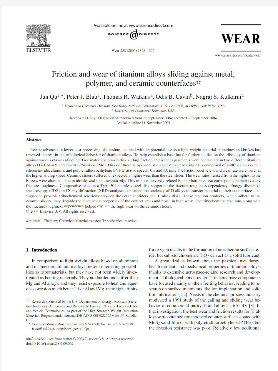
Fig.1.Microstructures of two Ti alloys.
of these alloys,provided by the supplier for these heats of ma-terial,are listed in Table 1and their microstructures are shown in Fig.1(a)and (b),respectively.The typical ?,?/?-phase grain structure can readily be identi?ed on the etched cross-section of Ti64.Ti6242has ?ner grain size and is dominated by ?-phase.The two alloys have similar microindentation hardness and tensile strength (see Table 1).
Friction and wear tests were conducted using a pin-on-disk apparatus.The diameter of the ?xed ball sliders was 9.53mm.As shown in Table 2,440C stainless steel,silicon nitride,alu-mina,and polytetra?uoroethylene (PTFE),were selected to represent metallic,ceramic,and polymeric bearing materials.The Ti alloy disks were 63.5mm diameter and 12.7mm thick.The disk surfaces were polished by 600grit wet SiC abrasive paper and the pre-test arithmetic average surface roughness (R a ),measured with a Taylor Hobson Talysurf TM 10stylus pro?lometer with a 2.5?m tip radius,was 0.11±0.02?m.Concentric wear tracks ranging from 18to 52mm in diameter were used,and the disk rotation rate was adjusted accordingly to provide either 0.3or 1.0m/s sliding speed.A 10N normal load was applied and the test was run for 500m sliding dis-tance.In follow-on experiments,and to provide a comparison to the results for the Ti alloy disks,a 304stainless steel disk (63.5mm diameter and 6.35mm thick)was tested against 440C stainless steel and ceramic (Si 3N 4and Al 2O 3)slid-ers under similar sliding conditions.The microindentation Vickers hardness of the 304stainless steel disk was about 3.16GPa,slightly lower than that of the Ti alloy disks.
The friction force was monitored by a load cell-based force measurement system.The wear volumes of the sliders and disks were determined by weight change measurements with an accuracy of 0.1mg.The wear factor is de?ned as the wear volume normalized by the applied load and the sliding
1350
J.Qu et al./Wear 258(2005)1348–1356
Table 2
Characteristics of slider materials Sliders
Supplier
Speci?cation Vickers hardness (GPa)Fracture toughness (MPa m 1/2)440C stainless steel McMaster-Carr
Grade 100Hardened 12.60a 23.7b Silicon nitride Cerbec East Granby,CT NBD200Grade 519.37a 5.2c Alumina Southern Bearing Service
AFBMA Grade 2524.75a 3–4c PTFE
W.M.Berg,Inc.East Rockaway,NY
–
N/A
N/A
a The Vickers hardness was measured using a 100g load.
b
The Izod impact strength of hardened 440C stainless steel is 4ft lb [8].The fracture toughness here was estimated based on Barsom–Rolfe’s empirical formula [9],with the assumption that the Izod impact strength is close to the Charpy V-notch impact strength.c The fracture toughness values were provided by the suppliers.
distance of the pin.All the tests were conducted in ambient air conditions with temperature and humidity in the range of 18–22?C and 52–62%,respectively.At least two dupli-cates were run at each test condition.Good repeatability was obtained in both friction and wear results.
3.Results
Results are summarized in Table 3(a)and (b)for Ti64and Ti6242,respectively.Friction and wear results are presented separately.3.1.Friction
Table 3(a)and (b)present the average friction coef?-cient and its ?uctuation at steady-state for each test con-dition.Selected friction traces of the four different sliders against Ti64disks are shown in Fig.2.The PTFE slider gen-erated a fairly smooth friction trace (Fig.2(d))due to its self-lubricating nature.The metal and ceramic sliders pro-duced friction coef?cient in the range of 0.34–0.50with rel-atively large ?uctuation,as illustrated in Fig.2(a)–(c).The
Table 3
Friction and wear results Slider material
Sliding speed 0.3m/s
1.0m/s
Friction coef?cient
Wear factor (mm 3/N m)Friction coef?cient
Wear factor (mm 3/N m)Ball
Disk Ball Disk (a)Ti–6Al–4V disks 440C stainless steel 0.50±0.05 6.9×10?6 1.7×10?40.35±0.05 1.6×10?6 1.5×10?4Silicon Nitride 0.47±0.07 3.8×10?5 3.5×10?40.36±0.07 6.2×10?6 1.3×10?4Alumina 0.49±0.07 5.7×10?5 5.7×10?40.44±0.07 1.6×10?5 2.0×10?4PTFE
0.28±0.001
8.4×10?4N/M a 0.29±0.001 6.1×10?4N/M a (b)Ti–6Al–2Sn–4Zr–2Mo disks 440C stainless steel 0.48±0.05 5.1×10?6 1.3×10?40.34±0.04 1.22×10?6 1.1×10?4Silicon nitride 0.47±0.08 4.4×10⁻⁵ 3.5×10?40.37±0.029.40×10-6 1.1×10?4Alumina 0.49±0.08 1.2×10?4 3.4×10?40.42±0.04 2.33×10?5 2.2×10?4PTFE 0.27±0.001
9.9×10?4
N/M a
0.29±0.0017.92×10?4
N/M a
a
N/M,not measurable.
large ?uctuation of the friction coef?cient was thought to be caused by formation and periodic,localized fracture of a transfer layer.Titanium alloy commonly transfers to the counterface when rubbing against other metals or ceramics [3–5].In this study,surface morphology examination and surface analysis con?rmed this tendency.A transfer layer was easily identi?ed on the wear scar of the 440C stain-less steel ball (see Fig.3(a)).The energy dispersive spec-troscopy (EDS)analysis detected Ti and/or Al on the worn surfaces of the metal and ceramic balls,as shown in Fig.4.More discussion on surface analysis can be found on Section 4.2.
For metal and ceramic balls,lower friction coef?cient and smaller instantaneous ?uctuation were observed at 1.0m/s compared to those at 0.3m/s,as shown in Table 3.At higher sliding speed,the contact area had higher temperature,which generally reduced the shear strength and led to lower friction forces.3.2.Wear
As shown in Table 3(a)and (b),up to ?ve times higher wear factors were obtained on both the slider and disk at 0.3m/s
J.Qu et al./Wear258(2005)1348–1356
1351
Fig.2.Frictional traces of different sliders against Ti64disks.
than those at1.0m/s.Similar sliding speed dependency was also reported by other researchers[5].
The Ti disks suffered high wear rates,in the order of 10?4mm3/N m,against the metal and ceramic balls,and harder sliders generated relatively more(or at least compara-ble)wear on the Ti disks.Although harder balls were expected to have higher wear resistance,the results in Table3(a)and (b)show a reverse order:the alumina ball wore more than the silicon nitride ball,which in turn wore more than the stainless steel ball.Remarkably,the wear factors of the ceramic balls were at least?ve times higher than those of the steel balls. Dong and Bell also reported a higher wear rate of an alumina ball than that of a steel ball when sliding against a Ti64disk [5].More analysis and discussion are presented in Section4.
Fig.3shows the wear scars on the metal and ceramic balls with features of abrasive wear,adhesive wear,and plas-tic deformation.Abrasive wear seemed to dominate the wear process at0.3m/s.Those wear scars were larger and?atter, corresponding to their higher wear factors.The wear scars generated at1.0m/s were smaller but much rougher with larger patches of transferred material implying more severe adhesive wear,possibly due to higher temperature at the con-tact area.EDS analysis also showed higher Ti and/or Al con-centration on the wear scars at1.0m/s.
The PTFE slider had the highest wear factor (10?3mm3/N m).Its counterface(Ti disk)was pro-tected by the polymeric layer transferred from the PTFE ball and had almost no surface damage except a few shallow circular groves ground by third body particles,probably some metal debris,embedded in the PTFE ball.
It has been seen that these two Ti alloys showed simi-lar friction and wear behavior.Therefore,discussion will be focused on Ti64only.
4.Discussion
The most unusual?nding of this study was the observa-tion that the relatively hard ceramic sliders wore considerably more severely than the softer stainless steel slider.Mechan-ical and chemical analyses have been conducted to try to explain these results.
4.1.Fracture toughness
The wear resistance of440C stainless steel,silicon car-bide,and alumina pins is in the reverse order as their relative Vickers hardness numbers,but in the same relative order as their fracture toughness.
Recognizing that the current work was on sliding wear,the abrasive wear of ceramics has been proposed to be a function of both hardness and fracture toughness[10].Further studies
1352J.Qu et al./Wear 258(2005)1348
–1356
Fig.3.SEM images of wear scars on the balls sliding against Ti64disks.
on ceramic wear mechanisms showed that fracture toughness
may play a dominating role in wear resistance.For example,Fischer [11]has demonstrated that,in the case of yttria sta-bilized zirconia ceramics,the wear resistance increases with the fourth power of fracture toughness.
The pin-on-disk apparatus is mainly intended to evaluate sliding wear,but in practice,the load history can consist of sliding and impact,since vibrations may occur if the disk surface is not perfectly normal to the axis of rotation.The tendency for impact to occur for small errors in alignment depends also on the sliding speed and how far the contact is from the center of rotation.Unlike sliding that usually causes plastic shearing in materials,impact may introduce catastrophic failures,such as cracking and crushing of the
J.Qu et al./Wear258(2005)1348–1356
1353
Fig.4.EDS analysis of the wear scars on the sliders. contact surfaces,leading to faster material removal and the production of sharp ceramic debris fragments that can in turn cause three-body abrasion.Brittle materials,like ceramics, are more sensitive to such repeated impact effects than are tougher metals.Rice et al.[12,13]have studied the wear rate and mechanism of compound impact(impact and sliding) on metals and superalloys.The material with lower fracture toughness had a higher wear rate and gave strong evidence for subsurface damage.
To test the dependency of the wear rate on fracture tough-ness,comparative tests were conducted on a304stainless steel disk sliding against the440C stainless steel,silicon ni-tride,and alumina sliders,under10N load and at0.3m/s speed for500m.Friction and wear results for the304stain-less steel disk are shown in Table4.The alumina,silicon nitride,and440C stainless steel balls had the wear rate from high to low.This con?rmed the fracture toughness effect. However,it has been noticed that the sliders against the steel Table4
Friction and wear results for304stainless steel disks against metal and ceramic sliders
Slider material Friction coef?cient Wear factor(mm3/N m)
Ball Disk
440C stainless steel0.55±0.05<1×10?6 2.52×10?4 Silicon nitride0.68±0.08 1.15×10?6 2.01×10?4 Alumina0.57±0.039.80×10?6 5.41×10?4 disk had much lower wear factors than those against the Ti disks at the same testing condition(see Tables3and4),while the304stainless steel and Ti64disks had similar hardness and comparable wear factors.This suggests that there might be other sources in?uencing the wear rate.
4.2.Tribochemical reactions
It is known that mechanically deformed surfaces usu-ally have different chemical reactivity than purely thermally stressed solids[14].Tribochemical reactions may signi?-cantly accelerate the wear process.Surface analyses(EDS and XRD)were conducted on the contact surfaces to explore the possibility of tribochemical reactions that may induce the unexpected high wear rates on the ceramic sliders.Fig.4 shows the EDS spectra of the wear scars on the balls that slid against the Ti64disks.The EDS analyses indicated Ti and Al on the worn surfaces of the steel and alumina balls(see Fig.4(a)and(c)),which indicate material transfer from the Ti64disk to the sliders.It is interesting to notice that only Al but no Ti was found on the wear scar of the silicon nitride ball (see Fig.4(b)).No Al was observed on the unworn region of this ball.This may imply that the detected Al was probably not in metallic form(otherwise Ti should be present too),but had chemical compounds with other elements,such as Si,O, and/or N present in Fig.4(b).
X-ray diffraction was then used to further analyze the wear scars on the ceramic sliders.A four-axis goniometer[15] was employed for the grazing incidence(2?)X-ray diffrac-tion measurements using Cu K?radiation and parallel beam optics.That technique eliminates the sample surface dis-placement errors due to the spherical shape.Fig.5shows the XRD patterns of the wear scar and debris generated by silicon nitride against Ti64.Fig.5(a)reveals that the wear scar on the silicon nitride ball contains silicon nitride(Si3N4) in both?-and?-phase and silicon oxide nitride(Si2N2O). Due to the peak superposition,silicon aluminum oxide nitride (Si5AlON7)cannot be distinguished from Si3N4.However, the presence of Al detected by EDS supports this possibility. As shown in Fig.5(b),the XRD analysis on the wear debris found titanium,silicon nitride,and titanium nitride,but no indication of titanium oxides.This was a little surprising be-cause titanium oxides have the lower Gibbs free energy of formation than the titanium nitride in the ambient environ-ment.One possible explanation is that the titanium oxides were amorphous due to severe plastic deformation and were
1354J.Qu et al./Wear 258(2005)1348
–1356
Fig.5.X-ray diffraction analysis of the wear scar and debris for silicon nitride sliding against Ti64.
not detected by XRD.The XRD pattern of the worn sur-face on the alumina ball sliding against a Ti64disk is shown
in Fig.6.The observed spinel (MgAl 2O 4)was probably a sintering aid.The XRD pattern may suggest some possibil-ity of forming titanium–aluminum intermetallic compounds (Al 3Ti,Al 2Ti),but there was no strong evidence.Titanium aluminides were also suspected by Dong and Bell [5]based on the XRD analysis of the wear debris produced by alumina sliding against Ti64.
The high wear rates of alumina and silicon nitride slid-ers may be attributed to the formation of chemical reac-tion products between them and the Ti and/or Al transferred from the Ti64disks.Such tribochemical reactions were also aided by the lower thermal conductivity of Ti that promotes
J.Qu et al./Wear258(2005)1348–1356
1355
Fig.6.X-ray diffraction pattern of the wear scar on the alumina slider against the Ti64disk.
a higher temperature near the interface.These reaction prod-ucts bonded to the ceramic contact surfaces may deteriorate their mechanical properties and result in micro fractures lead-ing to high wear.The wear process continuously developed “fresh surfaces”and in turn accelerated the tribochemical re-actions.
5.Summary
The tribological behavior and responsible wear mech-anisms for titanium alloys Ti–6Al–4V and Ti–6Al–2Sn–4Zr–2Mo,sliding against440C stainless steel,silicon nitride, alumina,and PTFE were investigated.The following obser-vations and conclusions were obtained:
(1)The two Ti alloys had similar friction and wear perfor-
mance,although their grain structures and compositions are different.
(2)Large frictional?uctuations occurred when metal and
ceramic balls slid against Ti alloy disks,probably caused by formation and periodic,localized fracture of a transfer layer.
(3)Higher friction coef?cient with larger?uctuation and
higher wear rate were observed at the lower sliding speed.
(4)Despite their higher hardness,ceramic sliders experi-
enced much higher wear and created more wear on the counterfaces than did the stainless steel sliders.
(5)Fracture toughness and tribochemical reactions have
been proposed to explain the unexpected high wear rates on the ceramic https://www.doczj.com/doc/4e6869912.html,parative tests on a304stain-
less steel disk supported the fracture toughness depen-dency of the wear rate.
(6)EDS and XRD analyses con?rmed material transfer from
the Ti alloy disks to their counterfaces and suggested possible tribochemical reactions. Acknowledgements
The authors with to acknowledge with appreciation Y. Kosaka of Titanium Metals Corporation,USA,for supply-ing alloy billets along with their chemical analyses.Support for this research was provided by the U.S.Department of Energy,Assistant Secretary for Energy Ef?ciency and Re-newable Energy,Of?ce of FreedomCAR and Vehicle Tech-nologies,as part of the High Strength Weight Reduction Ma-terials Program,under contract DE-AC05-00OR22725with UT-Battelle,LLC.J.Qu and N.Kulkarni were supported in part by appointments to the ORNL Postdoctoral Research As-sociates Program administered jointly by ORNL and ORISE. References
[1]F.M.Kustas,M.S.Misra,Friction and wear of titanium alloys,in:
P.J.Blau(Ed.),ASM Handbook,Friction,Lubrication,and Wear Technology,18,ASM International,1992,pp.778–784.
[2]R.B.Waterhouse,A.Iwabuchi,The effect of ion implantation on the
fretting wear of four titanium alloys at temperatures up to600?C,in: Proceedings of the International Conference on Wear of Materials, ASME,New York,1985,pp.471–484.
1356J.Qu et al./Wear258(2005)1348–1356
[3]K.G.Budinski,Tribological properties of titanium alloys,Wear151
(1991)203–217.
[4]A.Molinari,T.B.Straffelini,T.Bacci,Dry sliding wear mechanisms
of the Ti6Al4V alloy,Wear208(1997)105–112.
[5]H.Dong,T.Bell,Tribological behavior of alumina sliding against
Ti6Al4V in unlubricated contact,Wear225–229(1999)874–884.
[6]EHKT Technologies,Opportunities for low cost titanium in re-
duced fuel consumption,improved emissions,and enhanced dura-bility heavy-duty vehicles,Oak Ridge National Laboratory Report, ORNL/Sub/4000013062/1,Oak Ridge,Tennessee,2002,p.59. [7]Ultra-Lite Brakes and Components,Literature,Red Devil Brakes,
Inc.,Mt.Pleasant,Pennsylvania,not dated.
[8]https://www.doczj.com/doc/4e6869912.html,mpman,Fatigue and fracture properties of stainless steel,in:
https://www.doczj.com/doc/4e6869912.html,mpman(Ed.),ASM Handbook,Fatigue and Fracture,19, ASM International,1996,pp.712–732.
[9]J.M.Barsom,S.T.Rolfe,Correlations between K IC and Charpy V-
notch test results in the transition temperature range,in:Impact
Testing of Materials STP466,ASTM,Philadelphia,1979,pp.281–302.
[10]A.G.Evans,D.B.Marshall,Fundamentals of Friction and Wear of
Materials,ASM,1980,p.439.
[11]T.E.Fischer,Friction and wear of ceramics,Scripta Metall.Mater.
24(1990)833–838.
[12]S.L.Rice,The role of microstructure in the impact wear of two
aluminum alloys,ASME Proc.Wear Mater.(1979)27–34.
[13]S.L.Rice,H.Nowotny,S.F.Wayne,Characteristics of metallic sub-
surface zones in sliding and impact wear,ASME Proc.Wear Mater.
(1981)47–52.
[14]G.Heinicke,Tribochemistry,Carl Hanser Verlag Munchen Wien,
Berlin,1984.
[15]H.Krause,A.Haase,X-Ray Diffraction System PTS for Powder,
Texture and Stress Analysis,in:H.J.Bunge(Ed.),Experimental Techniques of Texture Analysis,vol.405–408,DGM Informations-gesellschaft,Verlag,1986.
陶瓷基摩擦材料的研究 白克江 (东营信义汽车配件有限公司山东东营257335) 摘要:本文通过对陶瓷基摩擦材料摩擦原理的探讨,分析了陶瓷配方的优异性,明确了摩擦性能调节剂在陶瓷配方中的重要作用,并利用国际先进的试验方法FMVSS135对配方性能进行了全面的研究。 关键词:陶瓷基摩擦材料摩擦性能调节剂 Abstract:The article analyzes the excellent of ceramics formula and makes clear the importance of friction regulator in ceramic formula by studying the principle of ceramic radicle and completely researching the formula function through the international advanced trial method FMVSS135. Keywords:Friction material of ceramic radicle Friction function regulator 一、前言 做为刹车片的摩擦材料,在满足人们正常使用中制动性能的同时,其使用寿命、环保性和舒适性也是人们非常关注的一个问题。而影响其使用寿命、环保性和舒适性的关键因素便是摩擦材料中基础增强材料和摩擦性能调节剂的选择和正确应用。 众所周知,石棉在摩擦材料中具有优秀的综合性能,但石棉有害健康,而且其在我国已经逐渐开始被禁用。半金属摩擦材料虽然因其比较优异的性能已经得到了广大用户的认可,但其易锈蚀、伤对偶、易发生噪音的缺点,一直在困惑着摩擦材料的研究者们,因此随着摩擦材料的发展,少金属和非金属摩擦材料应运而生,本文探讨的便是NAO摩擦材料中的一种:陶瓷基摩擦材料。 陶瓷基摩擦材料是一种利用无机矿物纤维和有机纤维做为增强材料,以改性树脂和橡胶粉为粘合剂,利用多种有机和无机材料做为摩擦性能调节剂配合加工而成的摩擦材料。其特点是无噪音、落灰少,不伤对偶、使用寿命长、无锈蚀。 二、基础摩擦材料的选择 1、增强纤维的选择 矿物纤维和陶瓷纤维的使用温度均可达到1000℃以上,具有良好的分散性能及高温稳定性,且价格比较便宜。这两种纤维的长径比比较小,虽然具有较大的比表面积,但其增强效果并不是十分的理想,因此本研究选用矿物纤维、陶瓷纤维及凯芙拉进行三元复合,来改善摩擦材料的高温摩擦性能和机械强度,以满
烧结金属摩擦材料现状与发展动态 newmaker 1 前言 烧结金属摩擦材料是以金属及其合金为基体,添加摩擦组元和润滑组元,用粉末冶金技术制成的复合材料,是摩擦式离合器与制动器的关键组件。它具有足够的强度,合适而稳定的摩擦系数,工作平稳可靠,耐磨及污染少等优点,是现代摩擦材料家族中应用面最大、量最大的材料。 用粉末冶金技术制造烧结金属摩擦材料已有70年的历史,1929年美国开始了这项工作的研究,30年代末期首先将该材料用在了D-7、D-8铲运机中的离合器片上。发展到现在,所有载荷量高的飞机,包括米格、伊尔、波音707、747和三叉戟等,其制动器摩擦衬材料都采用了烧结金属摩擦材料。在我国,特别是在1965年以后,烧结金属摩擦材料的科研、生产得到迅速发展。迄今,我国已有十多个具有一定生产规模的生产企业,年产铜基和铁基摩擦制品约850万件,广泛应用于飞机、船舶、工程机械、农业机械、重型车辆等领域,基本满足了国内主机配套和引进设备摩擦片的备件供给和使用要求。 2 制造方法与工艺研究 2.1 制造方法 目前,国内外烧结金属摩擦材料的生产仍主要沿用1937年美国S·K·Wellman及其同事们创造的钟罩炉加压烧结法(压烧法),该方法的基本工序是:钢背板加工→往油、电镀铜层(或铜、锡层);配方料混合→压制成薄片→与钢背板烧结成一体→加工沟槽及平面。由于传统的压烧法存在着能耗大、生产效率相对低、原材料粉末利用率低、本钱高等缺点。因此,一些国家对传统工艺作了一些改进,同时十分注重新工艺的研究,在改善或保证产品性能条件下探索和寻求进步经济效益的途径。 新的制造工艺相继问世,其中最令人瞩目的是喷撒工艺(Sprinkling powder procedure),它以生产的高效率和明显的经济效益独具上风。喷撒工艺法以产业规模生产烧结金属摩擦材料始于70年代,美国的威尔曼、西德的奥林豪斯和尤里特、奥地利的米巴等企业拥有这项技术。80年代中期,杭州粉末冶金研究所从奥地利米巴公司引进了该技术。 喷撒工艺的基本流程是:钢背板在溶剂(如四氯化碳中脱脂处理(或钢背板电镀)→在钢背板上喷撒上混合材料→预烧→压沟槽→终烧→精整。 与传统的压烧法相比,喷撒工艺主要有下列一些优点: (1)实现了无加压连续烧结,耗能低。
金属硫化物陶瓷摩擦材料的制备与性能研究 李双君,魏明坤 (武汉理工大学理学院,湖北武汉430070) 摘要:以硫粉、锡粉、三硫化二锑为烧结剂,再加入其他辅助原料,利用金属硫化物的低熔点烧结制备陶瓷摩擦材料。研究了原料的不同配比对金属硫化物陶瓷摩擦材料的体积密度、气孔率、力学性能、摩擦性能以及显微结构的影响。硫含量对金属硫化物陶瓷摩擦材料性能有很重要的影响,通过对比寻求较为理想的原料配比,并对其实际应用的可行性进行探讨。 关键词:硫化物陶瓷;摩擦材料;性能 Preparati on ofM etal Sulfi des Cera m i c Friction M aterial and its Properties LI Shuang-jun,WE I M ing-kun (Schoo l o f Sc i e nce,W uhan Un iversity of Techno l o gy,H ube iW uhan430070,Chi n a) Abst ract:E le m ental su lfur,ti n powder and anti m ony trisu lfide used as sinteri n g agents,and then added other sup-porti n g m aterials,w ith lo w m elti n g po i n tm etal su lfides sinteri n g,cera m ic fricti o n m ater i a lw as prepared.The ra w m ater-i als of different proporti o ns ofm etal su lfide cera m ic friction m ateria l b u l k density,porosity,m echanical properties,friction properties and m icr oscopic structure w ere studied.Su lfur content had a sign ificant i m pact on m eta l sulfi d e cera m ic friction m aterial perfor m ance,By co m pari n g the ratio o f ra w m ateria ls,a m ore satisfactory rati o of ra w m aterials w as found ou,t and the feasi b ility of the ir practical app lication w as discussed. K ey w ords:su lfi d e cera m ic;friction m ateria;l property 车载摩擦片发展到现在,大概分为四种类型:石棉基摩擦衬片、半金属摩擦制动衬片、无石棉摩擦制动衬片和金属基烧结摩擦制动衬片[1]。 石棉基摩擦材料因为有致癌作用已遭淘汰。半金属摩擦材料中钢纤维容易生锈,锈蚀后易出现粘着对偶或者损伤对偶,使摩擦片强度降低,磨损加剧,摩擦系数稳定性变差;当摩擦温度高于300e时,易出现剥落现象,密封圈软化和制动液发生气化而造成制动失灵;易产生低速下的低频噪音。金属基摩擦材料磨损率高、摩擦传载力矩低、高温下性能衰退严重等,难以适用在重载干式离合器中[2]。 目前,虽然很多无石棉摩擦材料的综合性能已得到进一步提高,但仍存在很多问题,如有的材料在性能提高的同时,成本也大幅度提高,有的材料则出现粘结强度不够、噪声大等问题,所以全面提高新型摩擦材料的性能仍是亟待解决的一项任务。 本课题利用硫化锡、三硫化二锑的熔点较低,以其为烧结剂,添加其它助剂在较低的温度下烧结制备金属硫化物陶瓷摩擦材料,有利于降低能耗及生产成本,使其具有良好的摩擦性能,有良好的应用前景。并研究了不同配比的原料对金属硫化物陶瓷性能的影响。 1实验部分 1.1试样制备 金属硫化物陶瓷材料的配比见表1。 表1金属硫化物陶瓷材料的配比(w t%) 试样编号升华硫锡粉三硫化二锑铁铝粉钢钎氧化铝粉石墨二硫化钼100253530532 213213530532 325183530532 437153530532 549123530532 651193530532 1.2实验过程 按照表1所示配方配料,然后进行球磨搅拌混料,将配好的原料装入模具中,在压力320M P a用粉末压样机压制成型,于可控硅高温炉中常压烧结,温度500e。保温2h后自然冷却,再将 # 101 # 2010年38卷第6期广州化工
第17卷 第4期摩擦学学报V o l17, N o4 1997年12月TR I BOLO GY D ec,1997研究简报(363~366) 陶瓷2石墨复合材料的摩擦磨损性能研究3 董利民 张宝清 田杰谟 李兆新 (清华大学核能技术设计研究院 北京 102201) 摘要 对陶瓷2石墨复合材料 GC r15钢摩擦副的摩擦磨损性能与GC r15钢 GC r15钢的作了 对比试验研究.结果表明:分别在干摩擦和10#机械油润滑下,陶瓷2石墨复合材料 GC r15钢的 摩擦因数均比GC r15钢自配副时的低,陶瓷2石墨复合材料试块的磨痕宽度也比GC r15钢试块 的小.硬质陶瓷颗粒与石墨均匀弥散共存,提高了材料的强度和硬度,从而改善了材料的耐磨 性. 关键词 石墨 陶瓷 复合材料 摩擦学性能 分类号 TQ174.758.22 陶瓷2石墨复合材料兼备石墨和陶瓷材料各自的优点,具有耐高温、耐磨损、抗腐蚀及导电和导热性能良好等特性.对于这类材料的力学性能和物理性能已有不少研究报道[1~5],但有关其摩擦磨损性能的研究却还未见文献公开发表.作者对陶瓷2石墨复合材料 GC r15钢摩擦副的摩擦磨损性能进行了试验研究,并且探讨了陶瓷2石墨复合材料的摩擦磨损机理. 1 试验部分 1.1 试样 用于环2块式摩擦磨损试验机的环试样系以淬火与回火处理的GC r15轴承钢制备而成,其被试表面经过磨削加工后的表面粗糙度R a=0.35Λm,表层硬度为H V750.环试样的尺寸为外径49.2mm和宽度13.0mm.块试样的材料共有含石墨质量分数(w c,下同)分别为0.1,0.2,0.3,0.4和0.5的5种陶瓷2石墨复合材料.这些材料都是将Si C和B4C等陶瓷粉与石墨粉按一定比例混合后热压烧结制备的,烧结温度2200℃,压力20M Pa.试块尺寸为12.35mm×12.35mm×19.00mm,其表面经过研磨与抛光处理.表1所列是试块材料的力学性能和表面粗糙度.此外,还用GC r15钢试块与高强度石墨块作了对比试验研究. 1.2 摩擦因数的测定 在M H K2500环2块式摩擦磨损试验机上分别进行干摩擦和10#机械油润滑条件下的摩 3国家“八五”科技攻关项目(852********) 1996203211收到初稿,1997206228收到修改稿 本文通讯联系人董利民. 董利民 男,1965年2月生,内蒙古人,1991年在清华大学获硕士学位,目前主要从事精细陶瓷材料的组成、结构与性能研究,发表论文10余篇,现为清华大学核能技术设计研究院副研究员. 张宝清 男,1944年10月生,北京市人,1968年毕业于北京钢铁学院金属物理系,目前主要从事陶瓷材料的制备工艺及其性能研究,发表论文30余篇,现为清华大学核能技术设计研究院副研究员. 田杰谟 男,1935年4月生,山东省人,1963年毕业于清华大学工物系,目前主要从事结构陶瓷、生物功能陶瓷及生物陶瓷材料的研究,发表论文50余篇、专著2部,现为清华大学核能技术设计研究院教授、博士生导师. 李兆新 男,1963年1月生,北京市人,大专程度,目前主要从事陶瓷材料制备工艺研究,发表论文3篇,现为清华大学核能技术设计研究院实验师.
摩擦材料 一、概论 摩擦材料是一种应用在动力机械上,依靠摩擦作用来执行制动和传动功能的部件材料。它主要包括制动器衬片(刹车片)和离合器面片(离合器片)。刹车片用于制动,离合器片用于传动。 任何机械设备与运动的各种车辆都必须要有制动或传动装置。摩擦材料是这种制动或传动装置上的关键性部件。它最主要的功能是通过摩擦来吸收或传递动力。如离合器片传递动力,制动片吸收动能。它们使机械设备与各种机动车辆能够安全可靠地工作。所以说摩擦材料是一种应用广泛又甚关键地材料。 摩擦材料是一种高分子三元复合材料,是物理与化学复合体。它是由高分子粘结剂(树脂与橡胶)、增强纤维和摩擦性能调节剂三大类组成及其它配合剂构成,经一系列生产加工而制成的制品。摩擦材料的特点是具有良好的摩擦系数和耐磨损性能,同时具有一定的耐热性和机械强度,能满足车辆或机械的传动与制动的性能要求。它们被广泛应用在汽车、火车、飞机、石油钻机等各类工程机械设备上。民用品如自行车、洗衣机等作为动力的传递或制动减速用不可缺少的材料。 二、摩擦材料发展简史 自世界上出现动力机械和机动车辆后,在其传动和制动机构中就使用摩擦片。初期的摩擦片系用棉花、棉布、皮革等作为基材,如:将棉花纤维或其织品浸渍橡胶浆液后,进行加工成型制成刹车片或刹车带。其缺点:耐热性较差,当摩擦面温度超过120℃后,棉花和棉布会逐渐焦化甚至燃烧。随着车辆速度和载重的增加,其制动温度也相应提高,这类摩擦材料已经不能满足使用要求。人们开始寻求耐热性好的、新的摩擦材料类型,石棉摩擦材料由此诞生。 石棉是一种天然的矿物纤维,它具有较高的耐热性和机械强度,还具有较长的纤维长度、很好的散热性,柔软性和浸渍性也很好,可以进行纺织加工制成石棉布或石棉带并浸渍粘结剂。石棉短纤维和其布、带织品都可以作为摩擦材料的基材。更由于其具有较低的价格(性价比),所以很快就取代了棉花与棉布而成为摩擦材料中的主要基材料。1905年石棉刹车带开始被应用,其制品的摩擦性能和使用寿命、耐热性和机械强度均有较大的提高。1918年开始,人们用石棉短纤维与沥青混合制成模压刹车片。20世纪20年代初酚醛树脂开始工业化应用,由于其耐热性明显高于橡胶,所以很快就取代了橡胶,而成为摩擦材料中主要的粘结剂材料。由于酚醛树脂与其他的各种耐热型的合成树脂相比价格较低,故从那时起,石棉-酚醛型摩擦材料被世界各国广泛使用至今。 20世纪60年代,人们逐渐认识到石棉对人体健康有一定的危险性。在开采或生产过程中,微细的石棉纤维易飞扬在空气中被人吸入肺部,长期间处于这种环境下的人们比较容易患上石棉肺一类的疾病。因此人们开始寻求能取代石棉的其它纤维材料来制造摩擦材料,即无石棉摩擦材料或非石棉摩擦材料。20世纪70年代,以钢纤维为主要代替材料的半金属材料在国外被首先采用。80年代-90年代初,半金属摩擦材料已占据了整个汽车用盘式片领域。20世纪90年代后期以来,NAO(少金属)摩擦材料在欧洲的出现是一个发展的趋势。无石棉,采用两种或两种以上纤维(以无机纤维为主,并有少量有机纤维)只含少量钢纤维、铁粉。NAO(少金属)型摩擦材料有助于克服半金属型摩擦材料固有的高比重、易生锈、易产生制动噪音、伤对偶(盘、鼓)及导热系数过大等缺陷。目前,NAO (少金属)型摩擦材料已得到广泛应用,取代半金属型摩擦材料。2004年开始,随汽车工业飞速发展,人们对制动性能要求越来越高,开始研发陶瓷型摩擦材料。陶瓷型摩擦材料主要以无机纤维和几种有机纤维混杂组成,无石棉,无金属。其特点为: 1. 无石棉符合环保要求; 2. 无金属和多孔性材料的使用可降低制品密度,有利于减少损伤制动盘(鼓)和产生制动噪音的粘度。 3. 摩擦材料不生锈,不腐蚀; 4. 磨耗低,粉尘少(轮毂)。 三、摩擦材料分类 在大多数情况下,摩擦材料都是同各种金属对偶起摩擦的。一般公认,在干摩擦条件下,同对偶摩擦系数大于0.2的材料,称为摩擦材料。 材料按其摩擦特性分为低摩擦系数材料和高摩擦系数材料。低摩擦系数材料又称减摩材料或润滑材料,其作用是减少机械运动中的动力损耗,降低机械部件磨损,延长使用寿命。高摩擦系数材料又称摩阻材料(称为摩擦材料)。
纳米氧化锆陶瓷材料摩擦磨损情况研究 青岛市技师学院王利利 近些年,很多学者对纳米氧化锆陶瓷的制备研究比较多,但是对其性能的研究相对较少一些。随着纳米材料的逐渐应用,尤其是医学应用领域,对其性能的要求越来越高,不仅要有良好的力学性能,还要有好的摩擦磨损性能。本文主要研究润滑条件下,纳米氧化锆陶瓷材料的摩擦磨损情况。 摩擦磨损实验用的试件是自制的3Y-TZP陶瓷块,纳米氧化锆复合粉体,在200Mpa的压力下,干压成型后再冷等静压成形,在1450oC常压烧结制备。经金刚石切割,精密磨床磨削加工后制成所需尺寸19X13X11.7。润滑液为10号机油,对磨环块是经淬火和回火处理而制成的GCr15钢环,摩擦表面也经过磨削加工并抛光。与纳米氧化锆陶瓷块对比的试件是氧化铝陶瓷块,含95%的三氧化二铝,尺寸同3Y-TZP陶瓷块。 润滑条件下的主要参数为:转速范围360转/分~840转/分,载荷(试验力)范围100N~1000N,室温,相对湿度为60%,润滑介质为10号机油。 一、摩擦系数 1.载荷对摩擦系数的影响 在10机油润滑条件下,测得的摩擦系数随载荷和转速的变化如图1所示。润滑条件下的摩擦系数明显比干摩擦时降低了很多,在0.05~0.14之间。从图中,我们可以看出来,随着法向载荷由100N到600N的逐渐增加,纳米ZrO2陶瓷材料的摩擦系数成上升趋势。因为加在试样上载荷增加了,两接触表面之间产生的摩擦力也大了,摩擦系数随着载荷的增加而上升,但是上升趋势越来越缓慢。 在转速240r/min的时候,摩擦系数随载荷变化不大,比较平稳;但是在840r/min的时候,摩擦系数随着载荷的波动变化比较大,100N至400N之间摩擦系数迅速上升,由0.0561迅速上升到0.1121,然后逐步平稳,在0.12附近波动。与其它几种常用的牙科医用材料相比,钛合金、镍铬合金在O.3左右,钴铬合金在O.25左右。A1203陶瓷的摩擦系数在0.45—0.70之间波 2 2.转速对摩擦系数的影响 从图1中,可以看出,无论载荷是多少,摩擦系数都随转速的增加而下降。分析其原因,在转速低的时候,试样与摩擦副的接触面磨合比较慢,粗糙度大,从而摩擦力就大,所以摩擦系数大;而转速高的时候,试样与摩擦副的接触面磨合迅速,表面的粗糙度小了,摩擦力就小了,所以摩擦系数就小。另外,转速增高了,摩擦表面产生了塑性变形,并且逐渐加剧,从而使接触面升温、软化,起到了润滑作用。所以,随着转速的增加,摩擦系数成下降趋势。 3.时间对摩擦系数的影响
烧结金属材料硬度规范 由于烧结金属材料硬度的检测和其他金属件有所不同。为了使图纸与工厂及生产厂商的实物检指能够保持一致,须统一标准与规范,经过统计多家供应商的烧结金属零件检指数据加以汇总分析,并参照一系列的国家标准,特编制烧结金属材料硬度的设计检测标准规范。 硬度硬度是烧结金属结构材料(零件)中最常使用的一个性能指标。按烧结金属结构材料(零件)的材质不同,常用的硬度测试方法有布氏硬度HB;洛氏硬度HRA、HRB、HRC;维氏硬度HV及肖氏硬度HS。它们的压头材料、压头大小、压头形状以及采用的压力各不相同。根据试样上压头所留下的压痕尺寸大小,可算出其相应的硬度值。 烧结金属结构材料通常存在孔隙。如果硬度计的压头正好压在它的孔隙处,就不能反映出其基体的真实硬度。多孔性材料的硬度值的离散性比相应的锻轧材料大。烧结金属零件的多孔性决定了其检测方法最好采用维氏硬度计,其值相对稳定而准确。烧结金属件中,含油(滑动)轴承仍用布氏硬度来表示其表观硬度。 经分析生产厂商送检的各类烧结金属零件检指数据,并参照相关国家标准规定: GB/T 9097.1-2002烧结金属材料(不包括硬质合金)表观硬度的测定第一部分:截面硬度基本均匀的材料 GB/T 4340.1-1999 金属维氏硬度试验第1部分试验方法 GB/T 231.1-2002 金属布氏硬度试验第1部分试验方法 对于烧结金属零件(含油轴承除外),在图纸上技术要求中硬度统一使用维氏硬度来标志,同样测试也使用维氏硬度标准。具体的测试统一按GB/T 4340.1-1999中3.3推荐的维氏硬度试验力表3-2,小负荷维氏硬度试验的HV0.3来标注和检测。 密度烧结金属材料制取零件时,材料具有孔隙,零件的密度是可变的。其不仅影响零件的力学性能和精度,同时影响压坯的成品率和生产效率,所以压坯密度设计是烧结金属的零件设计和制造的主要依据之一。在烧结金属零件生产中,一般说来,材料的密度愈高 ,材料的物理—力学性能愈高。烧结金属零件的密度是单位体积的质量,其体积也包含材料中孔隙的体积。 含油率含油率高低是含油轴承性能的重要指标,并与开孔率有关。测试参照国家标准: GB/T 5163-2006 烧结金属材料(不包括硬质合金)可渗性烧结金属材料密度、含油率和开孔率的测定来进行 烧结金属零件在图纸技术要求中必须要有硬度和密度二项指标,齿轮类还须增加材料抗拉及冲击强度极限值的技术要求。具体参照国家标准: GB/T 10423-2002 烧结金属摩擦材料抗拉强度的测定。 一.烧结金属材料-结构件 硬度与密度的分类:统一使用维氏硬度HV0.3,同时以零件在整机中的使用状态分为以下五大类。
制动器摩擦片材料介绍 目前,国内外用于制动的摩擦材料主要有石棉树脂(国家法规已限制使用)型摩擦材料、无石棉树脂型摩擦材料、金属纤维增强摩擦材料、半金属纤维增强摩擦材料和混杂纤维增强摩擦材料等,国内以半金属纤维增强摩擦材料的应用最为普遍。上述这些摩擦材料的基本成分是增强纤维摩擦材料的生产过程一般为: 原料储存→称重→混合→预成型(常温模)→高温压模→样品修饰处理→检视→包装出厂。 1、石棉、钢纤维及克维拉(芳纶纤维)制动片的典型配方 a.石棉制动片配方一般为:50%石棉、15%树脂、20%耐磨粒、15%填充料。 b.钢纤维制动片配方一般为:30%钢纤维、15%树脂,10%氧化锌,10%金属粉,15%陶瓷,10%橡胶粒、10%石墨。 c.芳纶纤维制动片配方一般为:5%芳纶纤维、15%金属粉、15%耐磨粒、15%树脂、50%填充料。 2、摩擦材料中各组分的作用 2.1增强纤维 纤维在摩擦材料中作为增强剂,对制动片的强度、摩擦和磨损性能起着重要作用。 2.2粘结剂树脂和纤维材料、填充料等各组分能否良好粘结,取决于树脂对这些材料的浸润性能以及与它们形成化学键的可能性。目前,摩擦材料最常用的粘结剂是各种酚醛树脂及其改性树脂,常用酚醛树脂的性能如表3所示,它的作用是将增强纤维与其他组分粘合在一起。粘结剂是摩擦材料的基体,直接影响到材料的各种性能,因此粘结剂应满足以下性能要求。 a.在一般温度(100℃以下)下,保证摩擦材料有足够的机械强度(抗击强度、冲击强度、压缩强度、剪切强度以及一定的伸长率)。 b.当制动摩擦表面温度在200~300℃时,树脂不发生粘流、分解,应保持一定的强度,以支持摩擦表面层的工作要求,且与对偶件有良好的贴合性。
—21— 新材料新装饰XINCAILIAOXINZHUANGSHI 2014年4期 汽车离合器用铜基金属 陶瓷摩擦材料的研究进展 冯超 徐吉波 魏子良 王琦 胡欢 (湖北汽车工业学院 材料科学与工程学院 十堰湖北 442002) 摘要:金属陶瓷摩擦材料具有吸能效率高、导热性好、摩擦系数高、耐高温、耐磨等特点,可用 于重型车、矿区用车、工程作业车、沙漠车等重载荷车辆以代替不抗热的有机摩擦片。本文综述了铜基金属陶瓷摩擦材料的发展现状,展望了铜基金属陶瓷摩擦材料的发展前景。 关键词:金属陶瓷;铜基摩擦材料;研究进展 1前言 汽车离合器靠摩擦来传递动力。当汽车行驶时,离合器的主动部件和从动盘相互压紧而一起旋转,但在起步、换档过程中,主、从动件之间相对摩擦,从动盘摩擦片发热并发生磨损。离合器的使用寿命主要取决于其从动盘摩擦片的耐磨性。通常汽车离合器从动盘摩擦片采用树脂基石棉材料做成。在160℃以上树脂片自身及其对偶件的磨损量都急剧增大,而金属陶瓷片在250℃以上仍保持很好的耐磨性,其对偶的磨损也很小。另一方面,金属陶瓷摩擦材料对铸铁的摩擦系数要比树脂石棉片对铸铁的摩擦系数高一些,因此用金属陶瓷摩擦片的离合器在同一夹紧载荷下,能比采用树脂片的离合器提供更大的摩擦力矩,亦即在保证相同的扭矩容量下所用的夹紧载荷减小,从而使离合器接合更柔和,在相同夹紧力下扭矩得到提高[1,2]。 2 铜基金属陶瓷摩擦材料的应用 从20世纪50年代起,国外就在拖拉机、工程机械及载货汽车上开始使用金属陶瓷磨擦材料作为离合从动盘的磨擦面片。由于金属陶瓷磨擦面片的磨擦系数高于有机石棉片,采用金属陶瓷磨擦面片的离合器与采用石棉片的离合器相比,在同一夹紧载荷下可提供更大的磨擦力矩,即离合器扭矩容量较大;而在同样大小的扭矩容量下,所用夹紧载荷较小,使离合器接合更平稳、柔和。此外,金属陶瓷材料比有机材料更耐高温,对于起步换挡频繁、离合器工作温度较高的汽车来说,用金属陶瓷材料更耐磨。据有关资料介绍,在温度160℃以下有机片的耐磨性还是比较好,但当温度更高时,其耐磨性急剧下降;而金属陶瓷材料则在接近300℃的高温下仍有较好的耐磨性。显然,对于使用条件恶劣的车辆来说,其离合器从动盘磨擦面的工作温度高,只有用耐高温的金属陶瓷材料才能保证足够长的使用寿命。据有关资料介绍,采用金属陶瓷片的离合器使用寿命比有机片的长75%。 3 国内外研究现状 金属陶瓷磨擦材料是由金属基体、陶瓷成份和润滑剂组成的一种多元复合材料。金属基体的主要作用是以机械结合的方式将陶瓷成份和润滑剂保持于其中,形成具有一定机械强度的整体;陶瓷成份主要起磨擦剂作用;而润滑剂成份则主要起提高材料抗咬合性和抗粘接性的润滑作用,特别有利于降低对偶材料的磨损,并使磨擦副工作平稳。润滑剂组分和陶瓷组分共同形成金属陶瓷磨擦磨损性能的调节剂。基体作为摩擦材料的主要组元,其作用主要是以机械结合方式将摩擦颗粒和润滑剂保持于其中,形成具有一定力学性能的整体。基体的强度是摩擦材料承载能力的反应,在很大程度上取决于基体的成分、结构和物理一力学性能。目前改善材料基体结构和强度主要从两个方面入手[3-4]:一是添加合金元素来强化基体。二是在较软的基体中添加强度较高的金属纤维或其它增强纤维。基体的组织结构、物理化学性质 在很大程度上决定了粉末冶金摩擦材料的力学性能、摩擦磨损性能、 热稳定性和导热性等整体性能的发挥。摩擦材料要求基体具有足够高 的熔点,高的耐热强度和热稳定性,工作温度内有较高的塑性变形抗 力,高的耐磨性。开展对基体成分及性能的研究至关重要,对提高铜 基金属陶瓷摩擦材料摩擦性能提供有益的指导。 对铜基金属陶瓷摩擦材料基体的研究,不能仅局限于基体本身,因为现代高性能粉末冶金摩擦材料大多是多组元的复合体,各个组元对材料性能的作用是相互影响的,因此研究基体的同时也应考虑其它组元加入后对基体的影响。目前在基体方面的研究工作,大都是在摩擦材料三大组元都存在的情况下来研究的,主要涉及以下各个方面:基体的类型;基体的物理、机械性能对摩擦磨损性能的影响;合金元素(辅助组元)对基体性能的影响;基体组织、硬相和塑性相的分布、第二相的影响、摩擦过程中表层组织的变化;材料中非金属组分与金属基体的相互作用、基体夹持硬质点的能力、粘结问题的研究;改善基体的压制、烧结等工艺性能研究摩擦过程中表层元素扩散过程研 究;基体塑变能力对摩擦磨损性能的影响,孔隙度大小、分布对基体 性能的影响;改善基体耐热性、耐磨性的研究等诸多方面[5-6]。 4 发展现状 目前,随着重载汽车离合器片的发展,以及离合器结构设计的紧凑性要求,对铜基金属陶瓷摩擦材料的耐磨性和耐热性提出了更高要求,特别是高温制动的稳定性。因此研究开发具有优异性能的新型铜基摩擦材料十分重要和迫切。为提高铜基摩擦材料的耐热性和耐磨性,主要途径:添加合金元素来强化提高基体的耐磨性和耐热强度;通过改变材料的摩擦剂与润滑剂,调节材料的成分,如添加铁和石墨等耐高温、耐磨材料来提高摩擦材料的整体性能。目前铜基纳米复合材料的研究成果表明:纳米氧化物作为弥散增强相所制备的弥散强化铜基复合材料,在保持铜本身高导热性能的同时还大幅度提高了强度及抗高温软化特性,具有其他强化方法无法比拟的优点。因此,将纳米材料应用于铜基摩擦材料,为改善摩擦材料的摩擦学性能提供了新途径。 参考文献: [1]黄建龙,王建吉,党兴武,陈生圣.铝含量对铜基粉末冶金材料性能的影响.润滑与密封,2013,38(1):56-60. [2]邓海金,李明,龚敏.钢纤维对铜基金属陶瓷摩擦材料力学和摩擦学性能的影响.摩擦学报,2004,24(4):336-340. [3]钟志刚,邓海金,李明,等.铁含量对铜基金属陶瓷摩擦磨损性能的影响.材料工程,2002,(8):17-19. [4]王晔,燕青芝,张肖路,等.石墨对铜基粉末冶金闸片材料性能的影响.粉末冶金技术,2012,30(6):432-439. [5]Xiong X,Sheng H C,Chen J,et al.Effects of sintering pressure and temperature on microstructure and tribological characteristic of Cu-based aircraft brake material.Transactions of nonferrous metals society of China,2007,17:669 -675. [6]湛永钟,张国定,曾建民,等.SiC 和石墨混杂增强铜基复合材料的高温摩擦磨损特性研究.摩擦学学报,2006,26(3):223-227. 基金项目:湖北汽车工业学院大学生创新性实验项目基金资助。
摩擦材料产品精编 Document number:WTT-LKK-GBB-08921-EIGG-22986
摩擦材料产品生产许可证实施细则
2007-04-04公布 2007-05-20实施 全国工业产品生产许可证办公室
目录 1总则 (1) 2工作机构 (2) 3企业取得生产许可证的基本条件 (3) 4许可程序 (4) 申请和受理.......................................................................................(4)企业实地核查....................................................................................(4)产品抽样与检验.................................................................................(5)审定和发证 (5)
集团公司的生产许可...........................................................................(5)5审查要求 (6) 企业生产摩擦材料产品的产品标准及相关标准 (6) 企业生产摩擦材料产品必备的生产设备和检测设备 (6) 摩擦材料产品生产许可证企业实地核查办法 (6) 摩擦材料产品生产许可证检验规则 (9) 6证书和标志 (21) 证书 (21) 标志 (22) 7委托加工备案程序..............................................................................(22)8收费 (23)
综述: 经过“十一五”期间的努力,摩擦密封材料行业取得了长足的进步。国际化步伐进一步加快,新技术研究、新产品开发、新材料应用、新设备换代、新工艺创造成绩斐然。行业总体规模和经济效益有了显著增长,2010年摩擦密封材料行业总产值由“十一五”初期的56.7亿元增加到101.51亿元,产品出口交货值由16.2亿元增加到37.14亿元,分别增长了79.03%和129.26%。 1.国外概况 1.1行业结构合理,产能集中度较高,跨国和跨地区经营进一步发展,产品生产逐步转移到劳动力便宜的发展中国家和地区进行,尤其注重向中国市场的转移。大部分主机配套集中在为数不多的零部件集团,如:辉门、霍尼韦尔、泰明顿、阿基波罗等。 1.2无石棉、少金属的环保型摩擦材料(又称NAO型摩擦材料)已经开始向市场推广; 消费者对制动噪音越来越重视,制动噪音已经成为区分车辆制动性能的关键因素之一,各大摩擦材料厂和制动系统生产厂家开始联合研究和开发低噪音制动系统,并取得了很多工程技术上的突破;通过控制产品压缩量来降低噪音已经成为各大摩擦材料厂质量控制的重要手段。 1.3欧美一些国家已经就限制摩擦材料中有害重金属组分及铜的含量进行立法。在可以预见的将来,摩擦材料中重金属组分的含量将会成为摩擦材料出口欧美的一项贸易限制。 1.4生产设备自动化控制和精密度较高,部分工序实现了连续化生产;因而生产效率比较高;原材料生产企业普遍具有相当规模且质量稳定,并能够根据用户需要对所供产品进行精加工和新的开发。 1.5大型摩擦材料企业拥有雄厚的科研力量和先进的研究测试设备,科研开发的资金投入普遍占到销售额的3~5%,有的甚至更高一些。他们不仅深入研究摩擦材料的表观和微观结构及性能,同时非常重视摩擦材料和对偶件及制动系统的整体匹配性研究。 1.6 把产品质量标准和测试方法标准作为一种日常工作,不断进行研究。国际同行对欧洲和北美地区采用的不同测试方法进行了有效的协调统一,标准全球化日趋成熟。 2 .国内概况 2.1 基本情况 随着我国国民经济的快速发展,汽车、摩托车、机械、铁路、石油、化工、船舶、航空、矿山、冶金等诸多领域对摩擦密封材料行业提出了更高的要求。铁路运输不断提速;城市轨道交通大量发展;汽
陶瓷摩擦材料摩擦性能影响因素探讨 摘要:本文探讨了外部因素和纤维对结构陶瓷摩擦磨损的影响,旨在促进在特定工况下正确使用相应的陶瓷材料作为摩擦学部件。 关键词:陶瓷摩擦材料摩擦性能 陶瓷是一种无机非金属材料,陶瓷材料一般具有较高的摩擦系数。陶瓷及其复合材料所具有的高熔点、高硬度、良好的化学稳定性、高温机械性能等特点,使其在众多领域中得到了实际应用,作为高温耐磨结构件具有比金属基材料更加广阔的应用前景。其中陶瓷纤维更是以其良好的抗老化性能、强度和在各种工作温度下保持稳定的摩擦能力而引起摩擦材料行业的广泛注意。将陶瓷材料用于制造阻摩器件,可利用其强度高、高温性能好、耐磨损等优良性能。另外,陶瓷材料的密度较低,如果将陶瓷材料制造的制动器在高速列车上成功应用,可使每个转向架上制动盘的总重量由1560kg下降到750kg。 1外部因素对工程陶瓷摩擦学特性的影响 外部因素是指一个完整的摩擦学系统中除了摩擦材料自身特性以外的因素,主要包括法向载荷、滑动速度、滑行距离、滑行时间、界面介质、环境气氛、温度、对摩材料、摩擦方式等。 1.1法向载荷的影响 研究者们普遍发现摩擦因数、磨损量随载荷增加而增加,但变化规律不是简单的线性递增关系,而是在某个载荷下摩擦因数有一明显跃变,磨损率也呈量级增加,国外的研究者们将之称作磨损突变(Wear Transition)。磨损率的突变对应着磨损机制的变化,即由塑性变形、犁耕、微切削和微断裂磨损转变为断裂磨损。研究表明在干摩擦条件下Y-TZP陶瓷材料在法向载荷大于142N时,轻微磨损突变为严重磨损,磨损机制由塑性变形转变为脆性断裂。同时,滑行速度对磨损行为有较大影响,在高速(≥1.26m/s)条件下发生了磨损突变。磨损由塑性变形转为断裂发生。在石蜡油润滑条件下A1203陶瓷在50N(10min)、ZTA复合陶瓷在320N(150min)时,磨损率发生突变。Kong等采用环一块式摩擦副,研究了自相配莫来石陶瓷在不同的介质和载荷下的摩擦磨损特性,实验结果表明:莫来石陶瓷以水为介质时在20N、以机油为介质时在1000N附近存在磨损突变。磨损突变前主要的磨损机理为塑性变形和犁耕:磨损突变后断裂磨损成为主要的磨损机理。机油为介质时,磨损率与载荷基本呈线性关系。 1.2滑动速度的影响 有关滑动速度对陶瓷摩擦磨损的影响,已经有不少学者作了这方面的研究。Esposito等研究表明在低滑行速度时氧化铝含量在79.0%-95.3%范围内的氧化铝陶瓷的磨损率随着氧化铝含量的降低而升高,但在高滑行速度时,此影响非常小。
乐 明 等:微珠陶瓷材料的摩擦磨损性能 第34卷第9期· 1099 · 微珠陶瓷材料的摩擦磨损性能 乐 明,杨金龙,席小庆,黄勇 (清华大学材料科学与工程系,新型陶瓷与精细工艺国家重点实验室,北京 100084) 摘要:由高温摩擦磨损试验研究了复合莫来石(22.6%硅酸锆,75%莫来石,2.4%碳酸钙,质量分数)、硅酸锆和氧化铝3种陶瓷微珠材料在干摩擦和水润滑条件下的摩擦磨损性能,并对其磨损机理进行了分析。结果表明:3种材料的磨损均随着负荷的增加而加剧;在同等载荷下,水润滑条件相对于干摩擦,复合莫来石和硅酸锆的磨损都有所降低,氧化铝磨损反而加剧。在低载荷下,微珠磨损机理主要是塑性变形和微裂纹,在较高载荷下,主要磨损机理是脆性剥落和磨粒磨损。 关键词:复合莫来石;硅酸锆;氧化铝;耐磨性;陶瓷微珠 中图分类号:TQ174 文献标识码:A 文章编号:0454?5648(2006)09?1106?06 WEAR RESISTANCE OF CERAMIC MICROBEADS YUE Ming, YANG Jinlong, XI Xiaoqing, HUANG Yong (State Key Laboratory of New Ceramics and Fine Processing, Department of Materials Science and Engineering, Tsinghua University, Beijing 100084, China) Abstract: The wear resistance and wear mechanism of three types of ceramic microbeads, mullite composite (22.6% zirconium sili-cate, 75% mullite, 2.4% calcium carbonate, in mass), zirconium silicate and alumina, were studied by a wear test under both dry and water lubrication conditions. The results show that the wear extent of the ceramics increases with the increase of the applied load. For water lubrication conditions compared with dry friction under same load, the wear of the mullite composite and zirconium silicate is mitigated but that of alumina increases. The main wear mechanism of the ceramics is plastic deformation and microcracks at lower loads, and brittlement stripping and grains pulling out at higher loads. Key words: mullite composite; zirconium silicate; alumina; wear resistance; ceramic microbeads 陶瓷微珠硬度大,强度高,耐高温,耐磨性好,有利于提高研磨效率,减少原料污染,提高产品质量,因此陶瓷微珠作为一种优良的研磨介质得到广泛应用[1–3]。陶瓷微珠主要是指直径为0.1~3mm之间的陶瓷小球,它的制备方法主要有熔融法、滚动成型法、等静压成型法等。同一种材料制备的磨球,由于生产方法及工艺的不同,产品质量会有差异,耐磨性能也不同。胶态注射成型工艺是结合凝胶注模和注射成型技术实现水基非塑性浆料成型的新工艺[4–5]。采用胶态注射成型新工艺生产的陶瓷微珠,其球形度高,微观结构致密,坯体强度高,耐磨性好。目前,用该方法生产的复合莫来石、硅酸锆、氧化铝等材料的微珠已经得到了工业应用。为此,用复合莫来石、硅酸锆、氧化铝3种陶瓷微珠材料,进行摩擦磨损试验,观察其磨损特性,研究其磨损机理,并分别在干摩擦和水润滑条件下进行摩擦磨损实验,通过对比探索润滑对这3种材料摩擦磨损的影响。 1 实验 1.1 样品制备 实验所用复合莫来石、硅酸锆和氧化铝微珠的化学组成见表1。 收稿日期:2006–02–22。修改稿收到日期:2006–05–17。 基金项目:国家863计划(2001AA337060和2004AA33G110)资助项目。第一作者:乐明(1982~),女,硕士研究生。 通讯作者:杨金龙(1966~),男,教授。Received date: 2006–02–22. Approved date: 2006–05–17. First author: YUE Ming (1982—), female, graduate student for master degree. Correspondent author: YANG Jinlong (1966—), male, professor. E-mail: jlyang@https://www.doczj.com/doc/4e6869912.html,. 第34卷第9期2006年9月 硅酸盐学报 JOURNAL OF THE CHINESE CERAMIC SOCIETY Vol. 34,No. 9 September, 2006
无石棉摩擦材料分为以下几类: a 半金属摩擦材料,应用于轿车和重型汽车的盘式刹车片。其材质配方组成中通常含有30%~50%左右的铁质金属物(如钢纤维、还原铁粉、泡沫铁粉)。半金属摩擦材料因此而得名。是最早取代石棉而发展起来的一种无石棉材料。其特点:耐热性好,单位面积吸收功率高,导热系数大,能适用于汽车在高速、重负荷运行时的制动工况要求。但其存在制动噪音大、边角脆裂等缺点。 b NAO摩擦材料。从广义上是指非石棉-非钢纤维型摩擦材料,但现盘式片也含有少量的钢纤维。NAO摩擦材料中的基材料在大多数情况下为两种或两种以上纤维(以无机纤维,并有少量有机纤维)混合物。因此NAO摩擦材料是非石棉混合纤维摩擦材料。通常刹车片为短切纤维型摩擦块,离合器片为连续纤维型摩擦片。 c 粉末冶金摩擦材料。又称烧结摩擦材料,系将铁基、铜基粉状物料经混合、压型,并在在高温下烧结而成。适用于较高温度下的制动与传动工况条件。如:飞机、载重汽车、重型工程机械的制动与传动。优点:使用寿命长;缺点:制品价格高,制动噪音大,重而脆性大,对偶磨损大。 d 碳纤维摩擦材料。系用碳纤维为增强材料制成的一类摩擦材料。碳纤维具有高模量、导热好、耐热等特点。碳纤维摩擦材料是各种类型摩擦材料中性能最好的一种。碳纤维摩擦片的单位面积吸收功率高及比重轻,特别适合生产飞机刹车片,国外有些高档轿车的刹车片也使用。因其价格昂贵,故其应用范围受到限制,产量较少。在碳纤维摩擦材料组分中,除了碳纤维外,还使用石墨,碳的化合物。组分中的有机粘结剂也要经过碳化处理,故碳纤维摩擦材料也称为碳——碳摩擦材料或碳基摩擦材料。 编辑本段5 摩擦材料的技术要求 5.1 适宜而稳定的摩擦系数 摩擦系数是评价任何一种摩擦材料的一个最重要的性能指标,关系着摩擦片执行传动和制动功能的好坏。它不是一个常数,而是受温度、压力、摩擦速度或表面状态及周围介质因素等影响而发生变化的一个数。理想的摩擦系数应具有理想的冷摩擦系数和可以控制的温度衰退。由于摩擦产生热量,增高了工作温度,导致了摩擦材料的摩擦系数发生变化。 温度是影响摩擦系数的重要因素。摩擦材料在摩擦过程中,由于温度的迅速升高,一般温度达200℃以上,摩擦系数开始下降。当温度达到树脂