
?Corresponding author.Tel.:+14169783115;fax: +14169786813.
E-mail addresses:david.potyondy@utoronto.ca(D.O.Potyondy), itasca@https://www.doczj.com/doc/455354554.html,(P.A.Cundall).
1Formerly with Itasca.
waves travel(e.g.,velocity,attenuation and scattering). Experimental observations reveal that most of the compression-induced cracks nucleate at the initial defects,such as grain boundaries or crack-like,low-aspect-ratio cavities,and that all compression-induced cracks are almost parallel to the direction of the maximum compression.The micromechanism respon-sible for the formation of these cracks is not understood fully;however,many possible models exist(e.g.,sliding deformation between the faces of initial defects inclined to the direction of maximum compression leading to formation of a wing crack at each of the two defect tips) that can reproduce many of the essential features of the brittle fracture phenomenon[1,7–15].Kemeny[10] asserts that:
Although the actual growth of cracks under compres-
sion may be due to many complicated mechanisms,as revealed by laboratory tests,it appears that they can all be approximated by the crack with a central point load.The origins of these‘‘point’’loads in rock under compression are small regions of tension that develop in the direction of the least principal stress. Kemeny and Cook[11]emphasize the importance of producing compression-induced tensile cracks: Laboratory testing of rocks subjected to differential compression have revealed many different mechan-isms for extensile crack growth,including pore crushing,sliding along pre-existing cracks,elastic mismatch between grains,dislocation movement,and hertzian contact.Because of the similarity in rock behavior under compression in a wide range of rock types,it is not surprising that micromechanical models have many similarities.This may explain the success of models based on certain micromechanisms (such as the sliding crack and pore models)in spite of the lack of evidence for these mechanisms in microscopic studies.
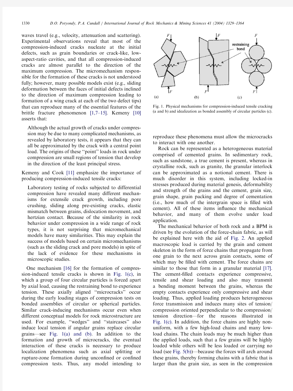
One mechanism[16]for the formation of compres-sion-induced tensile cracks is shown in Fig.1(c),in which a group of four circular particles is forced apart by axial load,causing the restraining bond to experience tension.These axially aligned‘‘microcracks’’occur during the early loading stages of compression tests on bonded assemblies of circular or spherical particles. Similar crack-inducing mechanisms occur even when different conceptual models for rock microstructure are used.For example,‘‘wedges’’and‘‘staircases’’also induce local tension if angular grains replace circular grains—see Fig.1(a)and(b).In addition to the formation and growth of microcracks,the eventual interaction of these cracks is necessary to produce localization phenomena such as axial splitting or rupture-zone formation during uncon?ned or con?ned compression tests.Thus,any model intending to reproduce these phenomena must allow the microcracks to interact with one another.
Rock can be represented as a heterogeneous material comprised of cemented grains.In sedimentary rock, such as sandstone,a true cement is present,whereas in crystalline rock,such as granite,the granular interlock can be approximated as a notional cement.There is much disorder in this system,including locked-in stresses produced during material genesis,deformability and strength of the grains and the cement,grain size, grain shape,grain packing and degree of cementation (i.e.,how much of the intergrain space is?lled with cement).All of these items in?uence the mechanical behavior,and many of them evolve under load application.
The mechanical behavior of both rock and a BPM is driven by the evolution of the force-chain fabric,as will be explained here with the aid of Fig.2.An applied macroscopic load is carried by the grain and cement skeleton in the form of force chains that propagate from one grain to the next across grain contacts,some of which may be?lled with cement.The force chains are similar to those that form in a granular material[17]. The cement-?lled contacts experience compressive, tensile and shear loading and also may transmit a bending moment between the grains,whereas the empty contacts experience only compressive and shear loading.Thus,applied loading produces heterogeneous force transmission and induces many sites of tension/ compression oriented perpendicular to the compression/ tension direction—for the reasons illustrated in Fig.1(c).In addition,the force chains are highly non-uniform,with a few high-load chains and many low-load chains.The chain loads may be much higher than the applied loads,such that a few grains will be highly loaded while others will be less loaded or carrying no load(see Fig.5(b))—because the forces will arch around these grains,thereby forming chains with a fabric that is larger than the grain size,as seen in the compression
Fig.1.Physical mechanisms for compression-induced tensile cracking (a and b)and idealization as bonded assembly of circular particles(c).
D.O.Potyondy,P.A.Cundall/International Journal of Rock Mechanics&Mining Sciences41(2004)1329–1364 1330
rings in Fig.6.2(The existence of such large-scale features in the force chains provides evidence that,in general,the mechanism shown in Fig.1(c)will be operative at a length scale larger than the grain size.)It is these microforces and micromoments that provide the local loading to produce grain and/or cement breakage, which,in turn,induces global force redistribution (because damaged material is softer and sheds load to stiffer,undamaged material)and the eventual formation of macroscopic fractures and/or rupture zones.As more and more grains and cement are broken,the material behaves more and more like a granular material with highly unstable force chains.The key to explaining material behavior is the evolving force-chain fabric, which is related in a complex way to the deformability and strength of the grains and the cement,the grain size, grain shape,grain packing and degree of cementation. Computational models of rock can be classi?ed into two categories,depending on whether damage is represented indirectly,by its effect on constitutive relations or,directly,by the formation and tracking of many microcracks.Most indirect approaches idealize the material as a continuum and utilize average measures of material degradation in constitutive rela-tions to represent irreversible microstructural damage [18],while most direct approaches idealize the material as a collection of structural units(springs,beams,etc.) or separate particles bonded together at their contact points and utilize the breakage of individual structural units or bonds to represent damage[19–22].Most computational models used to describe the mechanical behavior of rock for engineering purposes are based on the indirect approach,while those used to understand the behavior in terms of the progress of damage develop-ment and rupture are based on the direct approach. The BPM is an example of a direct modeling approach in which particles and bonds are related to similar objects observed microscopically in rock [23–30].Alternative rock models in which the material is represented as a continuum include those in Refs.[31,32],where a network of weak planes is superimposed on an otherwise homogeneous elastic continuum,and those in Refs.[33,34],where the stiffness and strength of elements in a continuum with initial heterogeneous strength are allowed to degrade based on a strength failure criterion in the form of an elastic–brittle–plastic constitutive relation.These rock models exhibit more realistic responses in terms of shear and post-failure behavior than most lattice models, because they can carry compressive and shear forces arising from loading subsequent to bond breakage, whereas most lattice models retain no knowledge of the particles after each bond has https://www.doczj.com/doc/455354554.html,prehensive review articles[35,36]summarize rock models and approaches for simulating crack growth,and[37] provides additional discussion of the BPM and its relation to other rock models.
The micromechanisms occurring in rock are complex and dif?cult to characterize within the framework of existing continuum theories.Microstructure controls many of these micromechanisms.The BPM approx-imates rock as a cemented granular material with an inherent length scale that is related to grain size and provides a synthetic material that can be used to test hypotheses about how the microstructure affects the macroscopic behavior.This is a comprehensive model that exhibits emergent properties(such as fracture toughness,which controls the formation of macroscopic fractures)that arise from a small set of microproperties for the grains and cement.The BPM does not impose theoretical assumptions and limitations on material behavior as do most indirect models(such as models that idealize the rock as an elastic continuum with many elliptical cracks—in the BPM,such cracks form,interact and coalesce into macroscopic fractures automatically). Behaviors not encompassed by current continuum theories can be investigated with the BPM.In fact, continuum behavior itself is simply another of the emergent properties of a BPM when averaged over the appropriate length scale.
Fig 2.Force and moment distributions and broken bonds(in
magenta)in a cemented granular material with six initial holes
idealized as a bonded-disk assembly in the post-peak portion of an
uncon?ned compression test.(Blue is grain–grain compression,while
black and red are compression and tension,respectively,in the cement
drawn as two lines at the bond periphery.Line thicknesses and
orientations correspond with force magnitude and direction,respec-
tively,and the moment in the cement contributes to the forces at the
bond periphery.)
2Figs.5(b)and6are discussed in detail in Section2.5,Material-
genesis procedure.
D.O.Potyondy,P.A.Cundall/International Journal of Rock Mechanics&Mining Sciences41(2004)1329–13641331
The remainder of the paper is organized as follows. The formulation of the BPM,which includes a micro-property characterization expressed in terms of grain and cement properties and a material-genesis procedure, is presented in the next section.In Sections3and4,the measured macroscopic properties of a BPM for Lac du Bonnet granite are presented and discussed.In Section3, the focus is on laboratory-scale behavior(during biaxial, triaxial and Brazilian tests),and Section4focuses on ?eld-scale behavior(involving damage formation adja-cent to an excavation).In both sections,the effect of particle size on model behavior is investigated.In Section5,the emergent properties of the BPM are listed,and the general source of some of these behaviors is identi?ed.As a particular example,a formal equivalence between the mechanisms and parameters of the BPM and the concepts and equations of linear elastic fracture mechanics(LEFM)is established and then used to explain the effect of particle size on model behavior.The capabilities and limitations of the BPM, as well as suggestions for overcoming these limitations, are presented in the conclusion.For completeness, the algorithms used to measure average stress and strain within the BPM,to install an initial stress?eld within the BPM,to create a densely packed BPM with low locked-in forces to serve as the initial material and to perform typical laboratory tests on the BPM are described in Appendix A.Throughout the paper, all vector and tensor quantities are expressed using indicial notation.
2.Formulation of the BPM
The BPM simulates the mechanical behavior of a collection of non-uniform-sized circular or spherical rigid particles that may be bonded together at their contact points.The term‘‘particle’’,as used here,differs from its more common de?nition in the?eld of mechanics,where it is taken as a body of negligible size that occupies only a single point in space;in the present context,the term‘‘particle’’denotes a body that occupies a?nite amount of space.The rigid particles interact only at the soft contacts,which possess?nite normal and shear stiffnesses.The mechanical behavior of this system is described by the movement of each particle and the force and moment acting at each contact.Newton’s laws of motion provide the funda-mental relation between particle motion and the resultant forces and moments causing that motion. The following assumptions are inherent in the BPM: 1.The particles are circular or spherical rigid bodies
with a?nite mass.
2.The particles move independently of one another and
can both translate and rotate.3.The particles interact only at contacts;because the
particles are circular or spherical,a contact is comprised of exactly two particles.
4.The particles are allowed to overlap one another,and
all overlaps are small in relation to particle size such that contacts occur over a small region(i.e.,at
a point).
5.Bonds of?nite stiffness can exist at contacts,and
these bonds carry load and can break.The particles at
a bonded contact need not overlap.
6.Generalized force–displacement laws at each contact
relate relative particle motion to force and moment at the contact.
The assumption of particle rigidity is reasonable when movements along interfaces account for most of the deformation in a material.The deformation of a packed-particle assembly,or a granular assembly such as sand,is described well by this assumption,because the deformation results primarily from the sliding and rotation of the particles as rigid bodies and the opening and interlocking at interfaces—not from individual particle deformation.The addition of bonds between the particles in the assembly corresponds with the addition of real cement between the grains of a sedimentary rock,such as sandstone,or notional cement between the grains of a crystalline rock,such as granite. The deformation of a bonded-particle assembly,or a rock,should be similar,and both systems should exhibit similar damage-formation processes under increasing load as the bonds are broken progressively and both systems gradually evolve toward a granular state.If individual grains or other microstructural features are represented as clusters of bonded particles,then grain crushing and material inhomogeneity at a scale larger than the grain size can also be accommodated by this model[38–40].
2.1.Distinct-element method(DEM)
The BPM is implemented in the two-and three-dimensional discontinuum programs PFC2D and PFC3D [41]using the DEM.The DEM was introduced by Cundall[42]for the analysis of rock-mechanics problems and then applied to soils by Cundall and Strack[43]. Thorough descriptions of the method are given in Refs. [44,45].The DEM is a particular implementation of a broader class of methods known as discrete-element methods,which are de?ned in Ref.[46]as methods that allow?nite displacements and rotations of discrete bodies, including complete detachment,and recognize new contacts automatically as the calculation progresses. Current development and applications of discrete-element methods are described in Ref.[47].
In the DEM,the interaction of the particles is treated as a dynamic process with states of equilibrium
D.O.Potyondy,P.A.Cundall/International Journal of Rock Mechanics&Mining Sciences41(2004)1329–1364 1332
developing whenever the internal forces balance.The contact forces and displacements of a stressed assembly of particles are found by tracing the movements of the individual particles.Movements result from the propa-gation through the particle system of disturbances caused by wall and particle motion,externally applied forces and body forces.This is a dynamic process in which the speed of propagation depends on the physical properties of the discrete system.The calculations performed in the DEM alternate between the applica-tion of Newton’s second law to the particles and a force–displacement law at the contacts.Newton’s second law is used to determine the translational and rotational motion of each particle arising from the contact forces,applied forces and body forces acting upon it,while the force–displacement law is used to update the contact forces arising from the relative motion at each contact.
The dynamic behavior is represented numerically by a time-stepping algorithm in which the velocities and accelerations are assumed to be constant within each time step.The solution scheme is identical to that used by the explicit?nite-difference method for continuum analysis.The DEM is based on the idea that the time step chosen may be so small that,during a single time step,disturbances cannot propagate from any particle farther than its immediate neighbors.Then,at all times, the forces acting on any particle are determined exclu-sively by its interaction with the particles with which it is in contact.Because the speed at which a disturbance can propagate is a function of the physical properties of the discrete system(namely,the distribution of mass and stiffness),the time step can be chosen to satisfy the above constraint.The use of an explicit,as opposed to an implicit,numerical scheme provides the following https://www.doczj.com/doc/455354554.html,rge populations of particles require only modest amounts of computer memory,because matrices are not stored.Also,physical instability may be modeled without numerical dif?culty,because failure processes occur in a realistic manner—one need not invoke a non-physical algorithm,as is done in some implicit methods.
2.2.Damping of particle motion
Because the DEM is a fully dynamic formulation, some form of damping is necessary to dissipate kinetic energy.In real materials,various microscopic processes such as internal friction and wave scattering dissipate kinetic energy.In the BPM,local non-viscous damping is used by specifying a damping coef?cient,a:The damping formulation is similar to hysteretic damping [48],in which the energy loss per cycle is independent of the rate at which the cycle is executed.The damping force applied to each particle is given by
F d?àa j F j signeVT;(1)where j F j is the magnitude of the unbalanced force on the particle and signeVTis the sign(positive or negative) of the particle velocity.This expression is applied separately to each degree-of-freedom.
Acommon measure of attenuation or energy loss in rock is the seismic quality factor,Q.The quality factor is de?ned as2p times the ratio of stored energy to dissipated energy in one wavelength
Q?2peW=D WT;(2)
where W is energy[49].For a single degree-of-freedom system,or for oscillation in a single mode,the quality factor can be written as[41]
Q?p=2a:(3)
All BPMs described in this paper were run with a damping coef?cient of0.7,which corresponds with a quality factor of 2.2.The quality factor of Lac du Bonnet granite in situ is about220[50];therefore,the models were heavily damped to approximate quasi-static conditions.Hazzard et al.[49]ran similar models using a damping coef?cient corresponding with a quality factor of100and found that the energy released by crack events(i.e.,bond breakages)may have a signi?cant in?uence on the rock behavior,because the waves emanating from cracks are capable of inducing more cracks if nearby bonds are close to failure. Hazzard and coworkers showed that the effect of this dynamically induced cracking was to decrease the uncon?ned compressive strength by up to15%.In addition,if low numerical damping is used,then seismic source information(such as magnitude and mechanism) can be determined for every modeled crack[51].
2.3.Grain-cement behavior and parameters
The BPM mimics the mechanical behavior of a collection of grains joined by cement.The following discussion considers each grain as a PFC2D or PFC3D particle and each cement entity as a parallel bond.The total force and moment acting at each cemented contact is comprised of a force,F i;arising from particle–particle overlap,denoted in Fig.3as the grain behavior,and a force and moment,ˉF i andˉM i;carried by the parallel bond and denoted as the cement behavior.These quantities contribute to the resultant force and moment acting on the two contacting particles.The force–dis-placement law for this system will now be described,?rst for the grain behavior and then for the cement behavior. Note that if a parallel bond is not present at a contact, then only the grain-based portion of the force–displace-ment behavior occurs.
The grain-based portion of the force–displacement behavior at each contact is described by the following six parameters(see Fig.3):the normal and shear stiffnesses,k n and k s;and the friction coef?cient,m;of
D.O.Potyondy,P.A.Cundall/International Journal of Rock Mechanics&Mining Sciences41(2004)1329–13641333
the two contacting particles,which are assumed to be disks of unit thickness in PFC2D and spheres in PFC3D.Whenever two particles overlap,a contact is formed at the center of the overlap region along the
line joining the particle centers (x ec T
i in Fig.3),and two linear springs are inserted (with stiffnesses derived from the particle stiffnesses assuming that the two particle springs act in series)along with a slider in the shear direction.
The contact force vector,F i (which represents the action of particle Aon particle B),can be resolved into normal and shear components with respect to the contact plane as F i ?F n n i tF s t i ;
(4)
where F n and F s denote the normal and shear force components,respectively,and n i and t i are the unit vectors that de?ne the contact plane.The normal force is calculated by F n ?K n U n ;
(5)
where U n is the overlap and K n is the contact normal stiffness given by K n
?
k eA Tn k eB Tn k n tk n ;(6)
with k eA Tn and k eB Tn
being the particle normal stiffnesses.
The shear force is computed in an incremental fashion.When the contact is formed,F s is initialized to zero.Each subsequent relative shear–displacement increment,D U s ;produces an increment of elastic shear force,D F s ;that is added to F s (after F s has been rotated to account for motion of the contact plane).The
increment of elastic shear force is given by D F s ?àk s D U s ;
(7)
where k s is the contact shear stiffness given by k s
?
k eA Ts k eB T
s k eA Ts tk eB Ts
;(8)
with k eA Ts and k eB T
s
being the particle shear stiffnesses.The relative displacement increment during the time step D t is given by D U i ?V i D t ;where V i is the contact velocity
V i ?_x ec Ti B
à_x ec Ti
A ?_x e
B Ti te ijk o eB Tj x ec Tk àx eB Tk à_x eA Ti te ijk o eA Tj x ec Tk àx eA Tk ;e9T
_x
i and o j are the particle translational and rotational velocities,respectively,and e ijk is the permutation symbol.The relative shear–displacement increment vector is
D U s i ?V s i D t ?eV i àV n
i TD t ?eV i àV j n j n i TD t :
(10)
If U n p 0(a gap exists),then both normal and shear forces are set to zero;otherwise,slip is accommodated by computing the contact friction coef?cient
m ?min m eA T;m eB Tàá
;(11)with m eA Tand m eB Tbeing the particle friction coef?cients,and setting F s ?m F n if F s 4m F n :
Fig.3.Force–displacement behavior of grain-cement system.
D.O.Potyondy,P.A.Cundall /International Journal of Rock Mechanics &Mining Sciences 41(2004)1329–1364
1334
Note that K n is a secant stiffness in that it relates total displacement and force,whereas k s is a tangent stiffness in that it relates incremental displacement and force.In this paper,an upper-case K denotes a secant stiffness and a lower-case k denotes a tangent https://www.doczj.com/doc/455354554.html,e of a secant stiffness to compute normal force makes the computations less prone to numerical drift and able to handle arbitrary placement of particles and changes in particle radii after a simulation has begun.
The cement-based portion of the force–displacement behavior at each cemented contact is described by the following ?ve parameters that de?ne a parallel bond (see Fig.3):normal and shear stiffnesses per unit area,ˉk n and ˉk s ;tensile and shear strengths,ˉs c and ˉt c ;and
bond-radius multiplier,ˉl ;such that parallel-bond radius ˉR
?ˉl min R eA T;R eB Tàá
;(12)
with R eA Tand R eB Tbeing the particle radii.Aparallel bond approximates the mechanical behavior of a brittle elastic cement joining the two bonded particles.Parallel bonds establish an elastic interaction between these particles that acts in parallel with the grain-based portion of the force–displacement behavior;thus,the existence of a parallel bond does not prevent slip.Parallel bonds can transmit both force and moment between particles,while grains can only transmit force.Aparallel bond can be envisioned as a set of elastic springs uniformly distributed over a rectangular cross-section in PFC2D and a circular cross-section in PFC3D lying on the contact plane and centered at the contact
point.These springs behave as a beam whose length,ˉL
in Fig.3,approaches zero to approximate the mechan-ical behavior of a joint.
The total force and moment carried by the parallel
bond are denoted by ˉF
i and ˉM i ;respectively,which represent the action of the bond on particle B.The force and moment vectors can be resolved into normal and shear components with respect to the contact plane as ˉF
i ?ˉF n n i tˉF s t i ;ˉM
i ?ˉM n n i tˉM s t i ;e13T
where ˉF
n ;ˉF s and ˉM n ;ˉM s denote the axial-and shear-directed forces and moments,respectively,and n i and t i are the unit vectors that de?ne the contact plane.
(For the PFC2D model,the twisting moment,ˉM
n ?0;and the bending moment,ˉM
s ;acts in the out-of-plane direction.)When the parallel bond is formed,ˉF
i and ˉM i are initialized to zero.Each subsequent relative displacement-and rotation increment D U n e;D U s ;D y n ;D y s with D y i ?o eB Ti ào eA T
i
D t
produces an increment of elastic force and moment that is added to the current values (after the shear-component vectors have been rotated to account for motion of the contact plane).The increments of elastic force and moment
are given by D ˉF
n ?ˉk n A D U n ;D ˉF
s ?àˉk s A D U s ;D ˉM
n ?àˉk s J D y n ;D ˉM
s ?àˉk n I D y s ;e14T
where A ;I and J are the area,moment of inertia and
polar moment of inertia of the parallel bond cross-section,respectively.These quantities are given by
A ?
2ˉRt
;t ?1;PFC2D ;p ˉR 2;PFC3D ;(
I ?
2ˉR 3t ;t ?1;PFC2D ;14
p ˉR 4
;PFC3D ;8<:J ?NA ;PFC2D ;12p ˉR 4;PFC3D :(e15T
The maximum tensile and shear stresses acting on the
parallel-bond periphery are calculated from beam theory to be
ˉs max ?
àˉF n
A
tj ˉM
s
j ˉR I ;ˉ
t max
?j ˉF s j A tj ˉM n j ˉR J
:e16TIf the maximum tensile stress exceeds the tensile strength eˉs max X ˉs c Tor the maximum shear stress exceeds the shear strength eˉt max X ˉt c T;then the parallel bond breaks,and it is removed from the model along with its accompanying force,moment and stiffnesses.
Asimpli?ed form of the BPM represents the cement using contact bonds instead of parallel bonds.Acontact bond approximates the physical behavior of a vanish-ingly small cement-like substance lying between and joining the two bonded particles.The contact bond behaves,essentially,as a parallel bond of radius zero.Thus,a contact bond does not have a radius or shear and normal stiffnesses,as does a parallel bond,and cannot resist a bending moment or oppose rolling;rather,it can only resist a force acting at the contact point.Also,slip is not allowed to occur when a contact bond is present.Acontact bond is de?ned by the two parameters of tensile and shear strengths,f n and f s ;expressed in force units.When the corresponding component of the contact force exceeds either of these values,the contact bond breaks,and only the grain-based portion of the force–displacement behavior occurs.
2.4.Microproperty characterization
In general,the BPM is characterized by the grain density,grain shape,grain size distribution,grain
D.O.Potyondy,P.A.Cundall /International Journal of Rock Mechanics &Mining Sciences 41(2004)1329–1364
1335
packing and grain-cement microproperties.Each of these items in?uences the model behavior.The grain density,r ;does not affect the quasi-static behavior but is included for completeness.In this paper,we focus on circular or spherical grains comprised of individual PFC2D or PFC3D particles,although the effect on the strength envelope of introducing particle clusters of complex interlocking shapes into the PFC2D particle assembly is discussed in Section 3.4.The particle diameters satisfy a uniform particle-size distribution bounded by D min and D max ;and a dense packing is obtained using the material-genesis procedure of Sec-tion 2.5.The packing fabric,or connectivity of the bonded assembly,is controlled by the ratio eD max =D min T;for a ?xed ratio,varying D min changes the absolute particle size but does not affect the packing fabric.Such a microproperty characterization separates the effects of packing fabric and particle size on material behavior and clearly identi?es D min as the controlling length scale of the material.The ?nal item that characterizes the BPM is the grain-cement microproperties:E c ;k n =k s àá;m èé
;grain microproperties ;ˉl ;ˉE c ;ˉk n =ˉk s àá;ˉs c ;ˉt c èé;cement microproperties ;e17Twhere E c and ˉE
c are the Young’s moduli of the grains an
d cement,respectively;ek n =k s Tand eˉk
n =ˉk s Tare the ratios of normal to shear stiffness of the grains and
cement,respectively;ˉl
is the radius multiplier used to set the parallel-bond radii via Eq.(12);m is the grain friction coef?cient;and ˉs c and ˉt c are the tensile and shear strengths,respectively,of the cement.In the analysis below,the grain and cement moduli are related to the corresponding normal stiffnesses such that the particle and parallel-bond stiffnesses are assigned as
k n :?
2tE c ;t ?1;PFC2D ;
4RE c ;PFC3D ;(
k s :?k n
ek n =k s T
;
ˉk n :?ˉE c R tR ;ˉk s
:?ˉk n eˉk n =ˉk s T;e18T
where R is particle radius.The usefulness of these modulus–stiffness scaling relations is con?rmed in Section 3.5,where it is shown that the macroscopic elastic constants are independent of particle size for the PFC2D material and exhibit only a minor size effect for the PFC3D material.
The deformability of an isotropic linear elastic material is described by two elastic constants.These quantities are emergent properties of the BPM and cannot be speci?ed directly.It is possible,however,to
relate the grain and cement moduli,E c and ˉE
c ;respectively,to the normal stiffnesses by envisioning
the material at each contact as an elastic beam with its ends at the particle centers,as shown in Fig.4.The axial stiffness of such a beam is K ?AE =L ;where A ,E and L are the cross-sectional area,modulus and length,respectively,of the beam.For the grain-based behavior,k n 2?eLt TE c L ?E c t )E c ?k n
2t
;t ?1;PFC2D ;k n 2?eL 2
TE c L ?E c L )E c ?k n 2L ?k n
4R
;PFC3D e19Tby assuming that k n ?k eA Tn ?k eB Tn in Eq.(6).For the cement-based behavior,
ˉk
n A ?A ˉE c L ?A ˉE c R tR )ˉE
c ?ˉk n R eA TtR eB Tàá:e20T
The cement modulus is dependent on particle size;to
achieve a constant cement modulus,parallel-bond stiffnesses must be scaled with the particle radii.For the PFC3D material,the grain modulus is dependent on particle size;to achieve a constant grain modulus,particle stiffnesses must be scaled with particle radius.This analysis does not yield a relation between Poisson’s ratio and particle stiffness at the microlevel;however,a macroscopic Poisson’s ratio will be observed,and its value will be affected by grain shape,grain packing and
the ratios ek n =k s Tand eˉk
n =ˉk s T:For a ?xed grain shape and packing,increasing these ratios increases the Poisson’s ratio.
2.5.Material-genesis procedure
The BPM represents rock as a dense packing of non-uniform-sized circular or spherical particles that are joined at their contact points with parallel bonds.The material-genesis procedure produces this system such that the particles are well connected and the locked-in forces are low.Both the packing and the locked-in
Fig.4.Equivalent continuum material of grain-cement system.
D.O.Potyondy,P.A.Cundall /International Journal of Rock Mechanics &Mining Sciences 41(2004)1329–1364
1336
forces are arbitrary and isotropic at a macroscale—i.e.,when averaged over approximately one dozen adjacent particles.(This would not occur if the material were created by gravity compaction—in which case,the force chains would be aligned vertically and their magnitudes would increase with depth.)The material-genesis proce-dure employs the following ?ve-step process (illustrated in Figs.5and 6for the PFC2D Lac du Bonnet granite model of Table 1).
https://www.doczj.com/doc/455354554.html,pact initial assembly :Amaterial vessel consisting of planar frictionless walls is created,and an assembly of arbitrarily placed particles is generated to ?ll the vessel.The vessel is a rectangle bounded by four walls for PFC2D and a rectangular parallele-piped bounded by six walls for PFC3D.The wall normal stiffnesses are made just larger than the average particle normal stiffness to ensure that the particle–wall overlap remains small.The particle diameters satisfy a uniform particle-size distribution bounded by D min and D max :To ensure a reasonably tight initial packing,the number of particles is determined such that the overall porosity in the
Fig.5.Material-genesis procedure for PFC2D model:(a)particle assembly after initial generation but before rearrangement;(b)contact-force distribution (All forces are compressive,thickness proportional to force magnitude.)after step 2;(c)?oating particles (with less than three contacts)and contacts after step 2;(d)parallel-bond network after step
4.
Fig. 6.Force and moment distributions in PFC2D material after removal from material-genesis vessel followed by relaxation (color convention described in Fig.2).
D.O.Potyondy,P.A.Cundall /International Journal of Rock Mechanics &Mining Sciences 41(2004)1329–1364
1337
vessel is 16%for PFC2D and 35%for PFC3D.
The particles,at half their ?nal size,are placed randomly such that no two particles overlap.Then,the particle radii are increased to their ?nal values,as shown in Fig.5(a),and the system is allowed to rearrange under zero friction.The ball-generation procedure is described in more detail in Appendix A.
2.Install speci?ed isotropic stress :The radii of all particles are reduced uniformly to achieve a speci?ed isotropic stress,s 0;de?ned as the average of the direct stresses.These stresses are measured by dividing the average of the total force acting on opposing walls by the area of the corresponding specimen cross-section.Stresses in the PFC2D models are computed assuming that each particle is a disk of unit thickness.When constructing a granite material,s 0is set equal to approximately 1%of the uniaxial compressive strength.This is done to reduce the magnitude of the locked-in forces that will develop after the parallel bonds are added and the specimen is removed from the material vessel and allowed to relax,as shown in Fig.6.The magnitude of the locked-in forces (both tensile and compressive)will be comparable to the magnitude of the compres-sive forces at the time of bond installation.The contact-force distribution at the end of this step is shown in Fig.5(b).The isotropic stress installation procedure is described in more detail in the Appendix A.
3.Reduce the number of ‘‘?oating’’particles :A
n assembly of non-uniform-sized circular or spherical particles,placed randomly and compacted mechani-cally,can contain a large number (perhaps as high as 15%)of ‘‘?oating’’particles that have less than N f contacts,as shown in Fig.5(c),where N f ?3:It is desirable to reduce the number of ?oating particles such that a denser bond network is obtained in step 4.In our granite models,we wish to obtain a densely packed and well-connected assembly to mimic a highly interlocked collection of grains.By setting N f ?3and the allowed number of ?oating particles to zero,we obtain a bonded assembly for which nearly all particles away from the specimen bound-aries have at least three contacts.The ?oater-elimination procedure is described in more detail in Appendix A.
4.Install parallel bonds :Parallel bonds are installed throughout the assembly between all particles that are in near proximity (with a separation less than 10à6times the mean radius of the two particles),as shown in Fig.5(d).The parallel-bond properties are assigned to satisfy Eqs.(17)and (18),with ˉs c and ˉt c picked from a Gaussian (normal)distribution.The grain property of m is also assigned.
5.Remove from material vessel :The material-genesis procedure is completed by removing the specimen from the material vessel and allowing the assembly to relax.This is done by deleting the vessel walls and stepping until static equilibrium is achieved.During the relaxation process,the material expands and generates a set of self-equilibrating locked-in forces,as shown in Fig.
6.These are similar to locked-in stresses that may exist in a free specimen of rock.The locked-in forces can be divided into two types,depending upon their existence at a macro-or a microscale.The macroscale forces exist within self-contained clusters of approximately one dozen particles,in which the inner particles are in tension and the outer particles are in compression,or vice versa.Such compression rings can be seen in Fig.6.The microscale forces exist within individual parallel bonds and are mostly tension to equilibrate the tendency of the contact springs to repel the com-pressed particles.There is a net energy stored in the assembly in the form of strain energy in both the particle–particle contacts and the parallel bonds.These locked-in forces can have a signi?cant effect upon behavior (e.g.,feeding energy into a rockburst or causing strain to occur when the assembly is cut).Holt [52]used a BPM to investigate stress-relief effects induced during coring of sandstone by setting s 0equal to the compaction stresses existing at the time of grain cementation.
Table 1
Model microproperties for Lac du Bonnet granite Grains
Cement
r ?2630kg =m 3
eD max =D min T?1:66;D min varies
ˉl ?1E c ?
62GPa ;PFC2D
72GPa ;PFC3D
&
ˉE
c ?62GPa ;
PFC2D
72GPa ;PFC3D
&
ek n =k s T?2:5eˉk n =ˉk s T?2:5
m =0.5
ˉs c ?ˉt c ?emean ?std :dev :T?
157?36MPa ;PFC2D 175?40MPa ;
PFC3D
&
D.O.Potyondy,P.A.Cundall /International Journal of Rock Mechanics &Mining Sciences 41(2004)1329–1364
1338
3.Measured macroscopic-properties(laboratory scale) The BPM consists of a procedure for material genesis and two independent sets of microproperties for short-and long-term behavior.Aset of short-term micro-properties are described in Section2.4,and a set of long-term microproperties are described in Ref.[53].No model is complete or fully veri?able[54],but the validity of the BPM is demonstrated by comparing model behavior with measured and observed responses of Lac du Bonnet granite at both laboratory and?eld scales in this and the next section.
3.1.Choosing microproperties
For continuum models,the input properties(such as modulus and strength)can be derived directly from measurements performed on laboratory specimens.For the BPM,which synthesizes macroscale material beha-vior from the interactions of microscale components,the input properties of the components usually are not known.The relation between model parameters and commonly measured material properties is only known a priori for simple packing arrangements.For the general case of arbitrary packing of arbitrarily sized particles,the relation is found by means of a calibration process in which a particular instance of a BPM—with a particular packing arrangement and set of model parameters—is used to simulate a set of material tests, and the BPM parameters then are chosen to reproduce the relevant material properties measured in such tests. The BPM for Lac du Bonnet granite is described by the microproperties in Table1.These microproperties were chosen to match the macroproperties of Lac du Bonnet granite discussed in Section 3.3.The ratio eD max=D minTis set greater than1to produce an arbitrary isotropic packing.AseD max=D minT!1;the packing tends toward a crystalline arrangement.Such a uniform packing exhibits anisotropic macroproperties and is not representative of the more complex grain connectivity of a granite.ˉl is set equal to1to produce a material with cement that completely?lls the throat between cemented particles.Asˉl!0;the material behavior approaches that of a granular material.The grain and cement moduli and ratios of normal to shear stiffness are set equal to one another to reduce the number of free parameters.Then,the moduli are chosen to match the Young’s modulus,and the ratios of normal to shear stiffness are chosen to match the Poisson’s ratio.Next, the cement strengths are set equal to one another so as not to exclude mechanisms that may only be activated by microshear failure(see below).The ratio of standard deviation to mean of the cement strengths is chosen to match the crack-initiation stress(de?ned in Section3.3), and the mean value of the cement strengths is chosen to match the uncon?ned compressive strength.The parti-cle-friction coef?cient appears to affect only post-peak response,and it is not clear to what it should be calibrated;thus,m?0:5is used as a reasonable non-zero value.
By settingˉs c?ˉt c;both tensile and shear microfai-lures are possible.If microtensile failure is excluded (by settingˉs c to in?nity),then cracking does not localize onto a single macrofracture plane under macroscopic extensile loading.Because this mechanism does occur in granite,microtensile failure is allowed to occur in the granite model.The alternative cases for which micro-shear failure is excluded fully(by settingˉt c to in?nity) or allowed(by settingˉs c?ˉt c)are investigated for the PFC2D material by Potyondy and Autio[39],who study damage formation adjacent to a circular hole subjected to far-?eld compressive loading.Both materi-als produce breakout notches in compressive regions and tensile macrofractures in tensile regions that are generally similar.The material withˉs c?ˉt c allows more well-de?ned notches to form than does the material that can only fail in the microtensile mode (see Fig.7).The former material accommodates the shearing deformation along the notch outline by forming a string of shear microcracks,whereas the latter material must form several sets of en echelon tensile microcracks(which requires that additional deformation and accompanying damage occur within the notch region).For the granite model,ˉs c?ˉt c so as not to exclude mechanisms that may only be activated via microshear failure.
3.2.PFC2D model behavior during biaxial and Brazilian tests
Typical stress–strain response and damage patterns are shown in Fig.8for the PFC2D granite model with an average particle diameter of0.72mm.The testing procedures are described in Appendix A.The crack distributions in this and all such?gures are depicted as bi-colored lines(in which red represents tension-induced parallel-bond failure for which bond tensile strength has been exceeded and blue represents shear-induced paral-lel-bond failure for which bond shear strength has been exceeded)lying between the two previously bonded particles with a length equal to the average diameter of the two previously bonded particles.The cracks are oriented perpendicular to the line joining the centers of the two previously bonded particles.The damage mechanisms during biaxial tests are summarized in observations1–3,and those during Brazilian tests in observation4.Similar observations apply to the PFC3D granite model subjected to triaxial and Brazilian tests.
1.During the early stages of biaxial loading,relatively
few cracks form,and those that do form tend to be aligned with the direction of maximum compression.
These cracks are distributed throughout the specimen
D.O.Potyondy,P.A.Cundall/International Journal of Rock Mechanics&Mining Sciences41(2004)1329–13641339
Fig.7.Damage in the notch region for the same compressive load (acting vertically)for a PFC2D material with (a)microshear failure allowed (3267cracks)and (b)microshear failure excluded (3800
cracks).
Fig.8.Stress–strain response and damage patterns formed during biaxial tests at con?nements of 0.1,10and 70MPa for a 63.4?126.8mm 2specimen of the PFC2D granite model with D avg ?0:72mm :(a)Stress-strain response;(b)Post-peak crack distribution,s 3?0:1MPa (1716cracks,tensile/shear=1452/264);(c)Post-peak crack distribution,s 3?10MPa (2443cracks,tensile/shear=2035/408);(d)Post-peak crack distribution,s 3?70MPa (3940cracks,tensile/shear=2800/1140).
D.O.Potyondy,P.A.Cundall /International Journal of Rock Mechanics &Mining Sciences 41(2004)1329–1364
1340
and do not seem to be interacting.The onset of this early cracking is quanti?ed by the crack-initiation stress.
2.Near peak load in a biaxial test,one or more
macroscopic failure planes develop that cut across the specimen.When con?nement is low,a set of secondary macrofractures oriented parallel with the loading direction form on either side of these failure planes,as seen in Fig.8(b).The secondary macro-fractures are comprised of tensile microcracks and suggest an axial-splitting phenomenon.As the con-?nement increases,the number of failure planes and their widths increase,as seen in Figs.8(c)and(d).
3.Damage at peak load is quite similar for all
con?nements,and most damage occurs after peak load as the specimen expands laterally—volumetric strain is dilational[53].This observation,combined with observation2,suggests that the post-peak damage-formation process is affected more by con-?nement than is the pre-peak damage-formation process.This change in behavior is related in part to the fact that,as con?nement increases,the ratio of shear microcracks to tensile microcracks increases.
The con?nement reduces the tensile forces that develop in a direction perpendicular to the specimen axis and thereby causes more shear microcracks to form.
4.During Brazilian tests,a wedge of cracks forms inside
of the specimen below each platen.Then,one of the wedges initiates a single macrofracture that travels across the specimen parallel with the direction of loading.The macrofracture is comprised of tensile microcracks and is driven by extensile deformation across the crack path(similar to an LEFM mode-I crack).This observation suggests that the Brazilian strength measured in these tests is related to the material fracture toughness,as is shown in Section
5.2,and that it may not correspond with the Brazilian
strength measured in a valid Brazilian test on a real rock specimen.Such dif?culties are inherent in tests that attempt to measure the tensile strength of a rock, because it is rarely possible to force the failure to
occur simultaneously across the entire?nal fracture plane.
3.3.Macroproperties of Lac du Bonnet granite
The following short-term laboratory properties of Lac du Bonnet granite[55]obtained from63-mm diameter specimens with a length-to-diameter ratio of2.5are used to calibrate the short-term response of the granite model (see Table2for mean,standard deviation and number of tests):(a)the elastic constants of Young’s modulus, E;and Poisson’s ratio,u;measured from uncon?ned compression tests;(b)the uncon?ned compressive strength,q u;(c)the crack-initiation stress,s ci;(d)the strength envelope for con?ning pressures in the range 0.1–10MPa approximated as an equivalent Mohr–Cou-lomb material with a secant slope,N f;friction angle,f; and cohesion,c;and(e)the Brazilian strength,s t:
The crack-initiation stress is de?ned as the axial stress at which non-elastic dilation just begins,identi?ed as the point of deviation from linear elasticity on a plot of axial stress versus volumetric strain.
The strength envelope,which is the relation between peak strength and con?ning pressure,is obtained by ?tting the Hoek–Brown strength criterion[56]to results of triaxial tests at con?ning pressures up to70MPa.The Hoek–Brown strength criterion is given by
s f?s3à
?????????????????????????
s s2
c
às3s c m
q
(21) where s and m are dimensionless material parameters and s c is equal to the uncon?ned compressive strength when s?1:The Hoek–Brown parameters for the strength envelope of Lac du Bonnet granite[57]are s c?213MPa;m?31and s?1:In general,the strength envelope will exhibit a decreasing slope for increasing con?nement;however,it can be linearized using a secant approximation de?ned by the strength,s f;at two con?nements,P0and P1:If the slope is de?ned by
N f?
s feP1Tàs feP0T
P1àP0
;(22)
Table2
Macroproperties of the models and Lac du Bonnet granite
Property Lac du Bonnet granite PFC2D model,D avg?0:72mm PFC3D model,D avg?1:53mm EeGPaT69?5:8en?81T70:9?0:9en?10T69:2?0:8en?10T
u0:26?0:04en?81T0:237?0:011en?10T0:256?0:014en?10T
q ueMPaT200?22en?81T199:1?13:0en?10T198:8?7:2en?10T
s cieMPaT90ts3;s3o3071:8?21:8en?10;s3?0:1T86:6?11:0en?10;s3?0:1Ts cdeMPaT150;s3?0NA190:3?7:5en?10;s3?0:1TN f133:01?0:60en?10T3:28?0:33en?10T
fedegT5929:5?4:8en?10T32:1?2:4en?10T
ceMPaT3058:5?8:5en?10T55:1?4:2en?10T
s teMPaT9:3?1:3en?39T44:7?3:3en?10T27:8?3:8en?10T
D.O.Potyondy,P.A.Cundall/International Journal of Rock Mechanics&Mining Sciences41(2004)1329–13641341
then the friction angle and cohesion can be written as[58]
f?sinà1
N fà1 N ft1
;
c?
q u
2
???????
N f
p;e23T
where q u is the uncon?ned compressive strength. The Brazilian strength is computed via
s t?
F f
p Rt
;(24)
where F f is the peak force acting on the platens,and R and t are the radius and thickness,respectively,of the Brazilian disk.
The crack-damage stress,s cd;is de?ned as the axial stress at which the volumetric strain reverses direction and becomes dilational.The crack-damage stress for saturated Lac du Bonnet granite is related to the peak strength,s f;by the following fourth-order poly-nomial[53]:
s cd
s f
?0:75à0:031xt0:00285x2
à0:000104x3t0:00000138x4;e25Twhere x is the con?ning stress(in MPa).The crack-damage stress is measured for the PFC3D material,but it is not used in the present calibration.
3.4.Macroproperties of the PFC models
The microproperties in Table1with D min?0:55mm and D min?1:19mm were used to produce PFC2D and PFC3D materials with average particle diameters of0.72 and1.53mm,respectively.Then,10rectangular PFC2D
specimens(63.4?31.7mm2)and10rectangular paralle-lepiped PFC3D specimens(63.4?31.7?31.7mm3)with different packing arrangements and microstrengths were created by varying the seed of the random-number generator during material genesis.Typical PFC2D/ PFC3D specimens(shown in Fig.9)contain approxi-mately4000/20,000particles and have44/20particles across the specimen width.Biaxial,triaxial and Brazilian tests were performed upon these specimens to obtain the model macroproperties shown in Table2.The testing procedures are described in Appendix A.The strength envelopes were obtained by performing a set of biaxial and triaxial tests at con?ning pressures of0.1,1,5,10, 20,30and70MPa.The test results for the PFC2D material are shown in Fig.10,which includes the peak strength and crack-initiation stress from each test with lines joining the average values at each con?ning pressure.The strength envelope for the PFC3D material is similar.
The PFC models match the macroproperties of E;n and q u of the Lac du Bonnet granite,and the variability of these macroproperties(expressed as a ratio of standard deviation to mean)is less than that of the physical material.The uncon?ned compressive strength of the PFC3D material exhibits less variability than that of the PFC2D material.The model materials also exhibit the onset of signi?cant internal cracking (measured by s ci)before ultimate failure.However,the model strengths only match that of the Lac du Bonnet granite for stresses near the uniaxial state.The slope of the strength envelope is too low(3for both PFC2D and PFC3D versus13for the granite),and the Brazilian strength is too high(the ratioeq u=s tTis4.5and7.2for PFC2D and PFC3D,respectively,versus21.5for the granite).This discrepancy may arise from the use of circular and spherical grains in the present model,and it could be reduced by using grain shapes that more closely resemble the complex-shaped and highly interlocked crystalline grains in granite.Apreliminary investigation, described below,suggests that introducing?nite-strength particle clusters of complex interlocking shapes into the PFC2D particle assembly will increase the slope
Fig.9.Typical specimens of the granite model:(a)PFC2D specimen (4017particles,7764parallel bonds)and(b)PFC3D specimen(19,749 particles,55,042parallel
bonds).
of the strength envelope and will lower the crack-damage stress.Asimilar effect is expected for the PFC3D material.If these grains are also allowed to break,then damage mechanisms that more closely resemble those in granite will be possible.One mechan-ism that contributes to the large difference in the compressive and tensile strengths of granite is suggested by Mosher et al.[59],who have studied the cracking within granite thin sections when stressed in tension or compression under the microscope and have found that intergranular fractures predominate in tension and intragranular in compression.
In the preliminary investigation,unbreakable particle clusters of complex interlocking shapes were introduced into the PFC2D particle assembly so that cracking is forced to occur along cluster boundaries(the white dots in Fig.11(a)).The clustering algorithm is controlled by S c;the maximum number of particles in a cluster.A cluster is de?ned as a set of particles that are adjacent to one another,where adjacent means that a connected path can be constructed between any two particles in a cluster by traversing bonded particle–particle contacts. The algorithm begins with a densely packed bonded material and identi?es particle clusters by traversing the list of particles.Each cluster is grown by identifying the current particle as a seed particle and then adding adjacent particles to the cluster until either all adjacent particles have been added or the cluster size has reached S c:The algorithm provides no control over cluster shape but does produce a collection of complex cluster shapes that are fully interlocking—similar to the interlocking grains in a crystalline rock.
The strength-envelope slope for such a material can be made to exceed that of Lac du Bonnet granite,as shown in Fig.11(b),and dilation begins at lower stresses relative to peak(s cd is lowered)as cluster size is increased.However,the biaxial-test damage does not localize into discrete macroscopic failure planes,and the post-peak response is plastic-like and does not exhibit the abrupt stress drop of Lac du Bonnet granite. Experiments on Barre granite[4]indicate that,after loading to approximately87%of peak strength,almost all grain boundaries were cracked along their entire length.Because this had occurred before the peak strength had been reached,it suggests that additional damage,in the form of transgranular fracture(or grain splitting)may be occurring in this loading regime.If a ?nite strength were assigned to the bonds within clusters,then transgranular fractures could form,and this might produce the desired localization and abrupt post-peak stress drop.This presents a promising avenue for further study[60].
3.5.Effect of particle size on macroproperties
If the BPM is used to predict damage formation surrounding an excavation,then the absolute size of the potential damage region is?xed,and successively?ner resolution models can be produced by decreasing D min while keeping all other microproperties?xed.The investigation in this section demonstrates that particle size is an intrinsic part of the material characterization that affects the Brazilian strength(and the uncon?ned compressive strength for PFC3D material);thus,parti-cle size cannot be regarded as a free parameter that only controls model resolution.If the damage mechanisms involve extensile conditions similar to those existing in a Brazilian test,then particle size should be chosen to match the Brazilian strength or another appropriate property of the rock,perhaps the fracture toughness. For the PFC3D material,it may not be possible to match the ratioeq u=s tTwithout introducing non-spherical grains.
Four PFC2D and four PFC3D granite materials were produced using the microproperties in Table1with
Fig.11.Introducing complex grain-like shapes into the PFC2D
material using particle clusters:(a)clusters of size7and bonds(black:
intra-cluster bonds;white:inter-cluster bonds)and(b)effect of cluster
size on strength envelope for unbreakable clusters.
D.O.Potyondy,P.A.Cundall/International Journal of Rock Mechanics&Mining Sciences41(2004)1329–13641343
different values of D min :The PFC2D and PFC3D materials have average particle diameters ranging from 2.87to 0.36mm and 5.95to 1.53mm,respectively.For each PFC2D and PFC3D material,10rectangular specimens (63.4?31.7mm 2)or 10rectangular paralle-lepiped specimens (63.4?31.7?31.7mm 3),respectively,with different packing arrangements and microstrengths were created by varying the seed of the random-number generator during material genesis.Each specimen was then subjected to a Brazilian test and to two biaxial or triaxial tests at con?nements of 0.1and 10MPa.The PFC3D Brazilian disk thicknesses were chosen to produce approximately 2.6particles across the thick-ness.The test results are presented in Tables 3and 4in terms of the mean and coef?cient of variation (ratio of standard deviation to mean)of each macroproperty.It is expected that as particle size continues to decrease,the coef?cients of variation will converge to speci?c values.These values should be a true measure of the effect of both packing and strength heterogeneities in the model materials,because the number of particles across the specimen has become large enough to obtain a representative sampling of the material response.As the number of particles across the specimen is reduced,the scatter in measured properties increases.Also,a suf?cient number of particles must be present for the model to resolve and reproduce the failure mechanisms that in?uence the strength properties.
3.5.1.PFC2D material response
The elastic constants appear to be independent of particle size.The mean values of Poisson’s ratio are approximately the same for all particle sizes,and the mean values of Young’s modulus increase slightly (by less than 5%)as particle size decreases from 2.87to 0.36mm.This slight increase in Young’s modulus may be an artifact of having sampled too few data points to obtain a true measure of the mean values.If the elastic constants truly are independent of particle size,then the characterization of the elastic grain-cement
microproperties in terms of E c ;ˉE
c ;ek n =k s T;an
d eˉk n =ˉk s Tprovides a size-independent means of specifying th
e elastic properties o
f the material.The size independence is achieved by scalin
g the parallel-bond stiffnesses as a function of particle size via Eq.(18).
The uncon?ned compressive strength also appears to be independent of particle size.The mean values differ by less than 8%and exhibit no clear increasing or decreasing trend.This behavior may be an artifact of having sampled too few data points to obtain a true measure of the mean values;however,the decreasing coef?cients of variation are reasonable and indicate a possible convergence to a speci?c value.It is also reasonable that the variability of q u is greater than the variability of the elastic constants,because q u measures a complex critical-state phenomenon involving extensive damage formation and interaction,whereas the elastic constants merely measure the deformability of the particle assembly before any signi?cant damage has developed.
No de?nitive statements about the effect of particle size on friction angle and cohesion can be made based on the results in Table 3.The mean values of f and c differ by 19%and 21%,respectively,and exhibit no
Table 3
Effect of particle size on PFC2D macroproperties Particle size D avg (mm)
Macroproperty (63.4?31.7mm 2specimens,n =10,mean and coef?cient of variation)E (GPa,%)
n (à,%)q u (MPa,%)f (deg,%)c (MPa,%)s t (MPa,%)2.8768.310.50.23119.0186.812.734.918.148.512.865.526.11.4468.8 3.30.2497.6184.47.930.323.853.418.954.312.20.7270.9 1.30.237 4.6199.1 6.529.516.358.514.544.77.40.36
71.5
0.8
0.245
2.9
194.8
4.1
33.0
17.3
53.3
14.4
35.4
7.6
Table 4
Effect of particle size on PFC3D macroproperties Particle size D avg (mm)
Macroproperty (63.4?31.7?31.7mm 3specimens,n =10,mean and coef?cient of variation)E (GPa,%)
n (à,%)q u (MPa,%)f (deg,%)c (MPa,%)s t (MPa,%)5.9557.310.00.23121.2127.911.925.914.240.011.443.627.83.0564.0 3.90.2548.1169.6 3.430.69.848.47.635.426.12.0467.6 1.80.255 5.8186.9 1.532.39.251.6 6.933.021.91.53
69.2
1.2
0.256
5.5
198.8
3.6
32.1
7.4
55.1
7.6
27.1
13.7
D.O.Potyondy,P.A.Cundall /International Journal of Rock Mechanics &Mining Sciences 41(2004)1329–1364
1344
clear increasing or decreasing trends.For the three smallest particle sizes,f and c exhibit the most variability of all measured properties.
The Brazilian strength exhibits a clear dependence upon particle size,with s t decreasing from65.5to 35.4MPa as particle size decreases from 2.87to 0.36mm.The coef?cients of variation have converged to approximately7.5%.The variability of s t is slightly greater than that of q u:This suggests that the critical-state conditions in a Brazilian test are more sensitive to packing and strength heterogeneities than are the critical-state conditions in an uncon?ned compres-sion test.
The measured decrease in Brazilian strength with decreasing particle size is explained in Section5.2,where it is shown that Brazilian strength is proportional to fracture toughness,which,in turn,is proportional to particle size.The lack of a similar size effect for q u suggests that the critical state in an uncon?ned compression test on the PFC2D material does not consist of the unstable growth of a single macrofracture subjected to extensile conditions.We speculate that a more complex critical state exists in which a failure plane and secondary macrofractures form under mixed compressive-shear conditions,and that such conditions are not sensitive to particle size.
3.5.2.PFC3D material response
The Poisson’s ratio is independent of particle size.The Young’s modulus exhibits a clear dependence on particle size,with E increasing from57.3to69.2GPa as particle size decreases from5.95to1.53mm.The characterization of the elastic grain-cement micropro-perties in terms of E c;ˉE c;ek n=k sT;andeˉk n=ˉk sTprovides a size-independent means of specifying the Poisson’s ratio of the material,but the Young’s modulus exhibits a minor size effect.
The uncon?ned compressive strength exhibits a clear dependence on particle size,with q u increasing from 127.9to198.8MPa as particle size decreases from5.95 to1.53mm.The coef?cients of variation have converged to approximately3.5%.The reason for this size effect is unknown.It corresponds with general observations that ?ner-grained rock is stronger than coarser-grained rock (medium and?ne-grained Lac du Bonnet granite [61,62]).Acredible explanation must encompass the fact that q u of the PFC2D material is independent of particle size.
No de?nitive statements about the effect of particle size on friction angle and cohesion can be made based on the results in Table4,although both properties seem to increase as particle size decreases.
The Brazilian strength exhibits a clear dependence upon particle size,with s t decreasing from43.6to 27.1MPa as particle size decreases from 5.95to 1.53mm.The coef?cients of variation have not yet converged.The variability of s t is much greater than that of q u:This suggests that the critical-state conditions in a Brazilian test are more sensitive to packing and strength heterogeneities than are the critical-state con-ditions in an uncon?ned compression test.
3.6.Effect of stress and damage on elastic constants The elastic constants of the BPM are affected by both stress and damage.These effects have been quanti?ed using a‘‘strain probe’’,which applies a speci?ed strain path to the particles at the boundary of an extracted core and monitors the stress–strain response using measurement regions within the core.Preliminary measurements performed upon the granite model indicate a reasonable correspondence with the proper-ties of Lac du Bonnet granite[53].The elastic constants are affected by the stress state as https://www.doczj.com/doc/455354554.html,pressive loading induces microtensile forces that act orthogonal to the compressive direction,and the particle motions that produce these microtensile forces modify the fabric (distribution of force chains)of the assembly.Increasing the mean stress increases the coordination number (average number of contacts per particle),which modi?es the magnitudes of the elastic constants but does not produce anisotropy.Anisotropy is produced by deviatoric stresses that modify the directional distribu-tion of the force chains—compressive loading increases the number of contacts oriented in the compressive direction and decreases the number of contacts oriented orthogonal to the compressive direction.These effects are enhanced by the presence of damage in the form of bond breakages.The elastic modulus dependence on mean and differential stress,as identi?ed in PFC modeling,has been qualitatively supported by in situ measurements of dynamic modulus[63].Ongoing work [64]aims to develop a quantitative link between AE/MS ?eld measurements of dynamic moduli and rock-mass damage by comparing the evolution of stress-and damage-induced modulus anisotropy in the PFC3D model with the results of both short-and long-term laboratory tests.
4.Measured macroscopic properties(?eld scale)
Three sets of boundary-value simulations were performed to demonstrate the ability of the two-dimensional BPM to predict the extent and fabric of damage that forms adjacent to an excavation and the effect of this damage on rock strength and deformability[53].The boundary-value simulations were of three experiments at Atomic Energy of Canada Limited’s(AECL)Underground Research Laboratory (URL)near Lac du Bonnet,Manitoba,Canada—namely,the Mine-by Experiment[65,66],the Tunnel
D.O.Potyondy,P.A.Cundall/International Journal of Rock Mechanics&Mining Sciences41(2004)1329–13641345
Sealing Experiment [67]and Stage 1of the Heated Failure Test [68].The Excavation Stability Study [69]also was simulated using slightly different microproper-ties.Asummary of comparisons between simulations and in situ observations is provided in Ref.[63].Extensive work has been done at the URL to characterize excavation-induced damage [70].One com-mon feature of this damage is the formation of breakout notches (apparently in regions where the elastic tangen-tial stress at the excavation boundary exceeds some critical value).This feature is investigated in the simulations,which embed the BPM within a larger continuum model such that only the region of a single notch is represented by the BPM.Only the results of the Mine-by Experiment simulations are presented here.
The Mine-by Experiment took place on the 420-m level of the URL in sparsely fractured Lac du Bonnet granite and consisted of carefully excavating a 3.5-m diameter circular tunnel subparallel with the direction of the intermediate principal stress.The tunnel was excavated in 1-m stages by drilling overlapping holes about the tunnel perimeter,and then removing the material using hydraulic rock splitters in closely spaced drill holes in the tunnel face.During tunnel excavation,a multistage process of progressive brittle failure resulted in the development of v-shaped notches,typical of borehole breakouts,in the regions of compressive stress concentration in the roof and ?oor (as shown in Fig.12).The major and minor in situ stresses are approximately 60and 11MPa,which produce an elastic tangential stress of 169MPa in the roof and ?oor.This induced stress is lower than the 200MPa uncon?ned compressive strength of the undamaged granite,and observation and analysis of other excavations at the 420-m level indicate that notches will form when the
elastic tangential stress in horizontal tunnels exceeds approximately 120MPa [69].
Various mechanisms have been suggested to account for the apparent degradation in material strength suf?cient to cause breakout.Two such mechanisms include precracking,which results from the local increase and rotation of stresses ahead of the advancing tunnel face,and stress corrosion—time-dependent cracking in rock that depends on load,temperature and moisture [71,72].Both of these mechanisms are investigated in Ref.[73]using a simpli?ed form of the BPM that represents the cement using contact bonds.(Acontact bond provides tensile and shear strengths only and behaves like a parallel bond with ˉk
n ?ˉk s ?ˉR ?0:)In that work,a time-dependent strength-degradation process was included in the sim-pli?ed BPM by reducing the contact-bond strength at a speci?ed rate if the contact force was above a speci?ed microactivation force.It was found that (a)precracking coupled with uniform strength reduction (choosing microproperties to match the long-term instead of the short-term strength of the rock)produced spalling and not distinct notches,and (b)activation of stress corrosion (for microproperties that match the short-term strength of the rock)produced notches that stabilized after approximately 56h.Subsequent work,summarized in Ref.[53],utilized the full BPM that represents the cement using parallel bonds,which allow one to mimic more closely the micromechanisms operative during stress corrosion by reducing the parallel-bond radius at a speci?ed rate if the maximum tensile stress in the parallel bond is above a speci?ed microactivation stress.In such models,notches are formed either by uniformly reducing the material strength everywhere or by activating stress corrosion.The difference in model behavior,particularly the ability to replicate notch development using a uniform strength reduction for the parallel bonds,is believed to be related to the use of parallel versus contact bonds.The parallel-bonded material becomes much more compliant in the damaged region than does the contact-bonded material,thereby shedding more load to the notch perimeter.4.1.Coupling the BPM with a continuum model The Mine-by Experiment was simulated using a coupled PFC2D-FLAC [74]model in which only the potential damage region is represented by the PFC2D material.The rectangular sample produced by the material-genesis procedure is installed into a corre-sponding rectangular void created in a FLAC grid adjacent to the tunnel surface,and a circular arc is removed from the particle assembly,corresponding to the tunnel boundary (see Fig.13).The basis of the coupling scheme is that FLAC controls the velocities of a layer of particles on three sides of the PFC2D region.
Fig.12.Photograph of broken and buckled rock slabs comprising the notch tip in the ?oor of the Mine-by Experiment tunnel.
D.O.Potyondy,P.A.Cundall /International Journal of Rock Mechanics &Mining Sciences 41(2004)1329–1364
1346
PFC2D returns the unbalanced forces of the same set of particles,and these are applied as boundary forces to the FLAC grid.A symmetry line,in the direction of the major principal stress,is used based on the assumption that cracking is similar in the roof and ?oor of the tunnel.The FLAC grid boundaries are placed at a distance of 10times the tunnel radius from the center.The elastic constants to be used in the FLAC grid are speci?ed,and the FLAC model is run in large-strain mode under conditions of plane strain.Coupling occurs during cycling such that each cycle in PFC2D corre-sponds with a cycle in FLAC.
Initially,the system is regarded as stress free.There are no initial stresses in the FLAC model,and the initial stresses in the PFC2D material are low relative to the ?nal stresses that will develop as a result of the excavation.In situ stresses are applied to the outer boundaries of the FLAC grid,and cycling is performed until equilibrium is established,indicating that the excavation-induced stress redistribution is complete.An alternative procedure would be to initialize stresses in the FLAC grid and install the same mean stresses in the PFC2D sample (using the stress-installation proce-dure described in Appendix A)prior to its connection to the FLAC grid.The resulting relaxation would corre-spond to the tunnel being created in a stressed material.Three PFC2D granite materials were produced using the microproperties in Table 1with different values of D min :The PFC2D materials have average particle diameters of 32,16and 8mm,respectively,and this corresponds with model resolutions of 33,66and 132particles across the 1.05-m extent of the potential damage region as shown in Fig.13.The elastic constants assigned to the FLAC grid were taken as the average values of Young’s modulus and Poisson’s ratio from Table 2.Although the PFC2D particle size that generated the data in Table 2was much smaller eD avg ?0:72mm T;the results in Table 3indicate that particle size
has only a minimal effect on the macroscopic elastic constants.
The modeling sequence mimics the rock genesis followed by the tunnel excavation.Two forms of strength reduction:uniform strength reduction,or activation of stress corrosion,were then applied to replicate the lower strength long-term response of the granite.The uniform strength reduction occurs by multiplying both the tensile and shear strengths of all parallel bonds by a speci?ed factor.The activation of stress corrosion introduces a time scale into the simulations such that the time evolution of the damage-formation process can be investigated—and,in cases where all microtensile stresses fall below the microactivation stress,a time to full damage stability can be determined.In this paper,the results from ?eld-scale simulations using a uniform strength-reduction factor are presented,whereas the stress-corrosion model is described elsewhere [53]and is only brie?y discussed in the following sections.
4.2.PFC2D model behavior during excavation-damage studies
In BPM simulations of the Mine-by Experiment,the notch-formation process is driven by either (a)mono-tonically increasing the far-?eld loading,(b)uniformly reducing the microstrengths (as shown in Fig.14,which includes the outline of the excavation,the outline of the PFC2D material,and a set of dashed circles spaced at intervals of R =5;where R is excavation radius),or (c)activating stress corrosion.The notch forms by a progressive failure process that starts at the excavation boundary in the region of maximum compression and proceeds inward.First,a small notch (group of
Fig.14.Effect of strength-reduction factor on damage patterns in the potential damage region of the Mine-by model for PFC2D granite model with D avg ?8mm :(a)Strength-reduction factor of 0.75(177cracks,tensile/shear=129/48);(b)Strength-reduction factor of 0.60(3428cracks,tensile/shear=2865/563);(c)Strength-reduction factor of 0.50(8076cracks,
tensile/shear=6704/1372).
Fig.13.PFC2D portion of coupled PFC2D-FLAC Mine-by model (PFC2D granite model with D avg ?32mm).
D.O.Potyondy,P.A.Cundall /International Journal of Rock Mechanics &Mining Sciences 41(2004)1329–1364
1347
microcracks)forms.Wing-cracks form near the notch tip and extend parallel with the current notch boundary, eventually curving toward and intersecting the bound-ary,forming slab-like pieces of material.These slabs do not detach fully,still being joined to the rock mass by some unbroken bonds,but do become much softer than the rock mass and,thus,shed load deeper into the rock mass.This increased load initiates additional wing cracks,which combine to extend the notch boundary. During this process,the notch is in a meta-stable state and only grows if the far-?eld load is increased,the microstrengths are reduced,or stress corrosion is active. The notch is meta-stable because the notch shape induces a compressive zone to form at the notch tip, which effectively strengthens the rock mass by reducing the microtensions that are driving the wing-crack growth.If the slabs are removed,the notch grows again to re-establish a new stable shape.
This meta-stable growth process continues until the notch reaches a critical depth relative to the tunnel radius,at which time the wing-cracks do not curve back toward the notch boundary;instead,they curve away from the boundary,forming what looks like a macro-scopic fracture(see Fig.14(c)).This secondary fracture is described in Ref.[39]as a‘‘shear band’’—an elongated cluster of microcracks that emanates from the apex of one or both notches and extends approxi-mately parallel with the excavation surface.Although there is no clear evidence for,or against,the formation of a shear band in the Mine-by Experiment,such features are often observed in laboratory tests.The rupture zone that formed in both the numerical(using a simpli?ed BPM that represents the cement using contact bonds instead of parallel bonds)and laboratory test of a rectangular prism of Berea sandstone contain-ing a circular hole and loaded in a plane strain (biaxial)test[75]may be such a feature.Potyondy and Autio[39]offer the following hypothesis regarding this feature:
It evolves from a band or‘‘cloud’’of microcracks.
The formation of this band seems to be related to a punching-type failure occurring at the top and/or bottom of the[excavation],in which the applied load tries to drive an intact rectangular region of material into the unloaded region surrounding the [excavation].(This unloaded region encompasses the notch tips and results from the presence of the notches,which are much more compliant than the surrounding rock and therefore shed load deeper into the rock away from the[excavation].)The micro-failure mode within the shear band need not be of a shearing type;many tensile microcracks may combine in an en-echelon fashion to accommodate the macroscopic shearing motion and thereby produce the shear band.4.3.Discussion of simulation results for the Mine-by models
No signi?cant damage forms as a result of excavation in any of the BPM simulations of the Mine-by Experiment;however,application of a strength-reduc-tion factor of0.6to the material with D avg?8mm produces a stable breakout notch as seen in Fig.14(b). Activation of stress corrosion to the material with D avg?8mm after excavation produces a notch that grows over time and does not fully stabilize before reaching the PFC2D-FLAC boundary,which occurs at a time of approximately14years.Anotch of similar extent(but different internal damage fabric)as that produced by a uniform strength-reduction factor of0.6 has formed after approximately2months of stress corrosion.
The notch-formation process is sensitive to the strength-reduction factor,as seen in Fig.14.It is not clear what procedure should be used to calibrate the strength-reduction factor,other than comparing the ?nal extent of any notches that form in boundary-value models of excavations.The use of a uniform strength-reduction procedure to predict excavation damage may be limited to qualitative assessments of the nature of the possible damage,and use of a properly calibrated stress-corrosion model may be required to make quantitative assessments.The stress-corrosion model was calibrated to match the static-fatigue behavior of the granite[76]. The fact that similar notches form for both strength-reduction procedures supports such use of a uniform strength-reduction approach.
The notch-formation process is sensitive to the particle size,as seen in Fig.15.Notches form more readily in material with smaller particles.One hypoth-esis to explain this behavior is that the material with
Fig.15.Effect of particle size on damage patterns in the potential damage region of the Mine-by model for PFC2D granite models with strength-reduction factors of0.6.(a)Davg=32mm(75cracks,tensile/ shear=59/16);(b)Davg=16mm(412cracks,tensile/shear=325/87);
(c)Davg=8mm(3428cracks,tensile/shear=2865/563).
D.O.Potyondy,P.A.Cundall/International Journal of Rock Mechanics&Mining Sciences41(2004)1329–1364 1348
关于努力工作的名人名言 1、最高的道德就是不断地为人服务,为人类的爱而工作。——甘地 2、自尊心、幻想、情思的早熟和智能的呆滞,再加上必然的后果。懒散,这些就是祸根。科学,劳动,实际工作。才能够使我们病态的,浪荡的青年清醒过来。——冈察洛夫 3、字典里最重要的三个词,就是意志、工作、等待。我将要在这三块基石上建立我成功的金字塔。——巴斯德 4、只有经过长时间完成其发展的艰苦工作,并长期埋头沉浸于其中的任务,方可望有所成就。——黑格尔 5、振兴世界的唯一办法是人人都做好眼前工作。切不可好高骛远,只求大功。——查·金斯莱 6、真正的自由属于那些自食其力的人,并且在自己的工作中有所作为的人。——罗·科林伍德 7、真正的学者真正了不起的地方,是暗暗做了许多伟大的工作而生前并不因此出名。——巴尔扎克 8、照亮我的道路,并且不断地给我新的勇气去愉快地正视生活的理想,是善、美和真。要是没有志同道合者之间的亲切感情,要不是全神贯注于客观世界——那个在艺术和科学工作领域里永远达不到的对象,那末在我看来,生活就会是空虚的。人们所努力追求的庸俗的目标——财产、虚荣、奢侈的生活——我总觉得都是可鄙的。——爱因斯坦
9、在学校和生活中,工作的最重要的动力是工作中的乐趣,是工作获得结果时的乐趣以及对这个结果的社会价值的认识。——爱因斯坦 10、一个人光溜溜地到这个世界上来,最后光溜溜地离开这个世界而去,彻底想起来,名利都是身外物,只有尽一个人的心力,使社会上的人多得他工作的裨益,是人生最愉快的事情。——邹韬奋 11、越工作越能工作,越忙碌越能创造出闲暇。—— 12、要正直地生活,别想入非非!要诚实地工作,才能前程远大。——陀思妥耶夫斯基 13、要对生命感到喜悦,因为它给了你去爱的机会,去工作,去玩乐,并用能仰头看星星的机会。——享利·凡·戴克 14、有远大抱负的人不可忽略眼前的工作。——欧里庇得斯 15、幸福存在于一个人真正的工作中。——奥理略 16、我只有在工作得很久而还不停歇的时候,才觉得自己的精神轻快,也觉得自己找到了活着的理由。——契诃夫 17、未来是光明而美丽的,爱它吧,向它突进,为它工作,迎接它,尽可能地使它成为现实吧!——车尔尼雪夫斯基 18、我所享有的任何成就,完全归因于对客户与工作的
8字模型与飞镖模型模型1:角的8字模型 如图所示,AC 、BD 相交于点O ,连接AD 、BC . 结论:∠A +∠D =∠B +∠C . O D C B A 模型分析 证法一: ∵∠AOB 是△AOD 的外角,∴∠A +∠D =∠AOB .∵∠AOB 是△BOC 的外角, ∴∠B +∠C =∠AOB .∴∠A +∠D =∠B +∠C . 证法二: ∵∠A +∠D +∠AOD =180°,∴∠A +∠D =180°-∠AOD .∵∠B +∠C +∠BOC =180°, ∴∠B +∠C =180°-∠BOC .又∵∠AOD =∠BOC ,∴∠A +∠D =∠B +∠C . (1)因为这个图形像数字8,所以我们往往把这个模型称为8字模型. (2)8字模型往往在几何综合题目中推导角度时用到. 模型实例 观察下列图形,计算角度: (1)如图①,∠A +∠B +∠C +∠D +∠E =________; 图图① F D C B A E E B C D A 图③ 2 1O A B 图④ G F 12 A B E 解法一:利用角的8字模型.如图③,连接CD .∵∠BOC 是△BOE 的外角, ∴∠B +∠E =∠BOC .∵∠BOC 是△COD 的外角,∴∠1+∠2=∠BOC . ∴∠B +∠E =∠1+∠2.(角的8字模型),∴∠A +∠B +∠ACE +∠ADB +∠E =∠A +∠ACE +∠ADB +∠1+∠2=∠A +∠ACD +∠ADC =180°. 解法二:如图④,利用三角形外角和定理.∵∠1是△FCE 的外角,∴∠1=∠C +∠E .
∵∠2是△GBD 的外角,∴∠2=∠B +∠D . ∴∠A +∠B +∠C +∠D +∠E =∠A +∠1+∠2=180°. (2)如图②,∠A +∠B +∠C +∠D +∠E +∠F =________. 图② F D C B A E 312图⑤ P O Q A B F C D 图⑥ 2 1 E D C F O B A (2)解法一: 如图⑤,利用角的8字模型.∵∠AOP 是△AOB 的外角,∴∠A +∠B =∠AOP . ∵∠AOP 是△OPQ 的外角,∴∠1+∠3=∠AOP .∴∠A +∠B =∠1+∠3.①(角的8字模型),同理可证:∠C +∠D =∠1+∠2.② ,∠E +∠F =∠2+∠3.③ 由①+②+③得:∠A +∠B +∠C +∠D +∠E +∠F =2(∠1+∠2+∠3)=360°. 解法二:利用角的8字模型.如图⑥,连接DE .∵∠AOE 是△AOB 的外角, ∴∠A +∠B =∠AOE .∵∠AOE 是△OED 的外角,∴∠1+∠2=∠AOE . ∴∠A +∠B =∠1+∠2.(角的8字模型) ∴∠A +∠B +∠C +∠ADC +∠FEB +∠F =∠1+∠2+∠C +∠ADC +∠FEB +∠F =360°.(四边形内角和为360°) 练习: 1.(1)如图①,求:∠CAD +∠B +∠C +∠D +∠E = ; 图 图① O O E E D D C C B B A A 解:如图,∵∠1=∠B+∠D ,∠2=∠C+∠CAD , ∴∠CAD+∠B+∠C+∠D+∠E=∠1+∠2+∠E=180°. 故答案为:180° 解法二:
美国常青藤名校的由来 以哈佛、耶鲁为代表的“常青藤联盟”是美国大学中的佼佼者,在美国的3000多所大学中,“常青藤联盟”尽管只是其中的极少数,仍是许多美国学生梦想进入的高等学府。 常青藤盟校(lvy League)是由美国的8所大学和一所学院组成的一个大学联合会。它们是:马萨诸塞州的哈佛大学,康涅狄克州的耶鲁大学,纽约州的哥伦比亚大学,新泽西州的普林斯顿大学,罗德岛的布朗大学,纽约州的康奈尔大学,新罕布什尔州的达特茅斯学院和宾夕法尼亚州的宾夕法尼亚大学。这8所大学都是美国首屈一指的大学,历史悠久,治学严谨,许多著名的科学家、政界要人、商贾巨子都毕业于此。在美国,常青藤学院被作为顶尖名校的代名词。 常青藤盟校的说法来源于上世纪的50年代。上述学校早在19世纪末期就有社会及运动方面的竞赛,盟校的构想酝酿于1956年,各校订立运动竞赛规则时进而订立了常青藤盟校的规章,选出盟校校长、体育主任和一些行政主管,定期聚会讨论各校间共同的有关入学、财务、援助及行政方面的问题。早期的常青藤学院只有哈佛、耶鲁、哥伦比亚和普林斯顿4所大学。4的罗马数字为“IV”,加上一个词尾Y,就成了“IVY”,英文的意思就是常青藤,所以又称为常青藤盟校,后来这4所大学的联合会又扩展到8所,成为现在享有盛誉的常青藤盟校。 这些名校都有严格的入学标准,能够入校就读的学生,自然是品学兼优的好学生。学校很早就去各个高中挑选合适的人选,许多得到全国优秀学生奖并有各种特长的学生都是他们网罗的对象。不过学习成绩并不是学校录取的惟一因素,学生是否具有独立精神并且能否快速适应紧张而有压力的大一新生生活也是他们考虑的重要因素。学生的能力和特长是衡量学生综合素质的重要一关,高中老师的推荐信和评语对于学生的入学也起到重要的作用。学校财力雄厚,招生办公室可以完全根据考生本人的情况录取,而不必顾虑这个学生家庭支付学费的能力,许多家境贫困的优秀子弟因而受益。有钱人家的子女,即使家财万贯,也不能因此被录取。这也许就是常青藤学院历经数百年而保持“常青”的原因。 布朗大学(Brown University) 1754年由浸信会教友所创,现在是私立非教会大学,是全美第七个最古老大学。现有学生7000多人,其中研究生近1500人。 该校治学严谨、学风纯正,各科系的教学和科研素质都极好。学校有很多科研单位,如生物医学中心,计算机中心、地理科学中心、化学研究中心、材料研究实验室、Woods Hole 海洋地理研究所海洋生物实验室、Rhode 1s1and反应堆中心等等。设立研究生课程较多的系有应用数学系、生物和医学系、工程系等,其中数学系海外研究生占研究生名额一半以上。 布朗大学的古书及1800年之前的美国文物收藏十分有名。 哥伦比亚大学(Columbia University) 私立综合性大学,位于纽约市。该校前身是创于1754年的King’s College,独立战争期间一度关闭,1784年改名力哥伦比亚学院,1912年改用现名。
第四章景观模型制作 第一节主要工具的使用方法 —、主要切割材料工具的使用方法 (—)美术刀 美术刀是常用的切割工具,一般的模型材料(纸板,航模板等易切割的材料)都可使用它来进行切割,它能胜任模型制作过程中,从粗糙的加工到惊喜的刻划等工作,是一种简便,结实,有多种用途的刀具。美术刀的道具可以伸缩自如,随时更换刀片;在细部制作时,在塑料板上进行划线,也可切割纸板,聚苯乙烯板等。具体使用时,因根据实际要剪裁的材料来选择刀具,例如,在切割木材时,木材越薄越软,刀具的刀刃也应该越薄。厚的刀刃会使木材变形。 使用方法:先在材料商画好线,用直尺护住要留下的部分,左手按住尺子,要适当用力(保证裁切时尺子不会歪斜),右手捂住美术刀的把柄,先沿划线处用刀尖从划线起点用力划向终点,反复几次,直到要切割的材料被切开。 (二)勾刀 勾刀是切割切割厚度小于10mm的有机玻璃板,ABS工程塑料版及其他塑料板材料的主要工具,也可以在塑料板上做出条纹状机理效果,也是一种美工工具。 使用方法:首先在要裁切的材料上划线,左手用按住尺子,护住要留下的部分,右手握住勾刀把柄,用刀尖沿线轻轻划一下,然后再用力度适中地沿着刚才的划痕反复划几下,直至切割到材料厚度的三分之二左右,再用手轻轻一掰,将其折断,每次勾的深度为0.3mm 左右。 (三)剪刀 模型制作中最常用的有两种刀:一种是直刃剪刀,适于剪裁大中型的纸材,在制作粗模型和剪裁大面积圆形时尤为有用;另外一种是弧形剪刀,适于剪裁薄片状物品和各种带圆形的细部。 (四)钢锯 主要用来切割金属、木质材料和塑料板材。 使用方法:锯材时要注意,起锯的好坏直接影响锯口的质量。为了锯口的凭证和整齐,握住锯柄的手指,应当挤住锯条的侧面,使锯条始终保持在正确的位置上,然后起锯。施力时要轻,往返的过程要短。起锯角度稍小于15°,然后逐渐将锯弓改至水平方向,快钜断时,用力要轻,以免伤到手臂。 (五)线锯 主要用来加工线性不规则的零部件。线锯有金属和竹工架两种,它可以在各种板材上任意锯割弧形。竹工架的制作是选用厚度适中的竹板,在竹板两端钉上小钉,然后将小钉弯折成小勾,再在另一端装上松紧旋钮,将锯丝两头的眼挂在竹板两端即可使用。 使用方法:使用时,先将要割锯的材料上所画的弧线内侧用钻头钻出洞,再将锯丝的一头穿过洞挂在另一段的小钉上,按照所画弧线内侧1左右进行锯割,锯割方向是斜向上下。 二、辅助工具及其使用方法 (一)钻床 是用来给模型打孔的设备。无论是在景观模型、景观模型还是在展示模型中,都会有很多的零部件需要镂空效果时,必须先要打孔。钻孔时,主要是依靠钻头与工件之间的相对运动来完成这个过程的。在具体的钻孔过程中,只有钻头在旋转,而被钻物体是静止不动的。 钻床分台式和立式两种。台式钻床是一种可以放在工台上操作的小型钻床,小巧、灵活,使
关于勤奋的谚语或名言 1、一分耕耘,一分收获。 2、暴风雨折不断雄鹰的翅膀。 3、学习如赶路,不能慢一步。 4、不怕走得慢,就怕路上站。 5、人为万物灵,全靠双手勤。 6、勤劳是个宝,一生离不了。 7、书中自有颜如玉,书中自有黄金屋。 8、天无一月雨,人无一世穷。 9、人往大处看,鸟往高处飞。 10、苟利国家生死以,岂因祸福避趋之。 11、发回水,积层泥;经一事,长一智。 12、勿以恶小而为之,勿以善小而不为。 13、船乘风破浪才能前进,人克服困难才能生存。 14、经历重大变故的人,容易成为智者。 15、要得惊人艺,须下苦功夫。 16、不怕山高,就怕脚软。 17、口说不如身到,耳闻不如目睹。 18、吃一回亏,学一回乖。 19、勤奋是幸福之母。 20、聪明在于勤奋,天才在于积累。 21、有苦干的精神,事情便成功了一半。
22、处处留心皆学问,三人同行有我师。 23、疾风知劲草,困难显英雄。 24、话中有才,书中有智。 25、不摸锅底手不黑,不拿油瓶手不腻。 26、你和时间开玩笑,它却对你很认真。 27、学在苦中求,艺在勤中练。 28、小人记仇,君子长志。 29、温固而知新,可以为师已。 30、宁做辛勤的蜜蜂,不做悠闲的知了。 31、谦虚是学习的朋友,自满是学习的敌人。 32、书山有路勤为径学海无涯苦作舟。 33、与有肝胆人共事,从无字句处读书。 34、天才就是这样,终身劳动,便成天才。 35、不吃苦中苦,难得甜上甜。 36、有钱难买少年时。 37、不与寒霜斗,哪来春满园。 38、三人行,必有我师焉。 39、玉不琢不成器,人不学不知义。 40、学而不思则罔,思而不学则殆。 41、学问之根苦,学问之果甜。 42、踏破铁鞋无觅处,得来全不费功夫。 43、劳动是百宝之根。
O D C B A 图12图E A B C D E F D C B A O O 图12图E A B C D E D C B A H G E F D C B A 第一章 8字模型与飞镖模型 模型1 角的“8”字模型 如图所示,AB 、CD 相交于点O , 连接AD 、BC 。 结论:∠A+∠D=∠B+∠C 。 模型分析 8字模型往往在几何综合 题目中推导角度时用到。 模型实例 观察下列图形,计算角度: (1)如图①,∠A+∠B+∠C+∠D+∠E= ; (2)如图②,∠A+∠B+∠C+∠D+∠E+∠F= 。 热搜精练 1.(1)如图①,求∠CAD+∠B+∠C+∠D+∠E= ; (2)如图②,求∠CAD+∠B+∠ACE+∠D+∠E= 。 2.如图,求∠A+∠B+∠C+∠D+∠E+∠F+∠G+∠H= 。
D C B A M D C B A O 135E F D C B A 105O O 120 D C B A 模型2 角的飞镖模型 如图所示,有结论: ∠D=∠A+∠B+∠C 。 模型分析 飞镖模型往往在几何综合 题目中推导角度时用到。 模型实例 如图,在四边形ABCD 中,AM 、CM 分别平分∠DAB 和∠DCB ,AM 与CM 交于M 。探究∠AMC 与∠B 、∠D 间的数量关系。 热搜精练 1.如图,求∠A+∠B+∠C+∠D+∠E+∠F= ; 2.如图,求∠A+∠B+∠C+∠D = 。
O D C B A O D C B A O C B A 模型3 边的“8”字模型 如图所示,AC 、BD 相交于点O ,连接AD 、BC 。 结论:AC+BD>AD+BC 。 模型实例 如图,四边形ABCD 的对角线AC 、BD 相交于点O 。 求证:(1)AB+BC+CD+AD>AC+BD ; (2)AB+BC+CD+AD<2AC+2BD. 模型4 边的飞镖模型 如图所示有结论: AB+AC>BD+CD 。
描写常青藤优美句段写常青藤作文散文句子 描写常青藤优美句段写常青藤作文散文句子第1段: 1.睁开朦胧的泪眼,我猛然发觉那株濒临枯萎的常春藤已然绿意青葱,虽然仍旧瘦小,却顽强挣扎,嫩绿的枝条攀附着窗格向着阳光奋力伸展。 2.常春藤是一种常见的植物,我家也种了两盆。可能它对于很多人来说都不足为奇,但是却给我留下了美好的印象。常春藤属于五加科常绿藤本灌木,翠绿的叶子就像火红的枫叶一样,是可爱的小金鱼的尾巴。常春藤的叶子的长约5厘米,小的则约有2厘米,但都是小巧玲珑的,十分可爱。叶子外圈是白色的,中间是翠绿的,好像有人在叶子上涂了一层白色的颜料。从叶子反面看,可以清清楚楚地看见那凸出来的,一根根淡绿色的茎。 3.渴望到森林里探险,清晨,薄薄的轻雾笼罩在树林里,抬头一看,依然是参天古木,绕着树干一直落到地上的常春藤,高高低低的灌木丛在小径旁张牙舞爪。 4.我们就像马蹄莲,永不分开,如青春的常春藤,紧紧缠绕。 5.我喜欢那里的情调,常春藤爬满了整个屋顶,门把手是旧的,但带着旧上海的味道,槐树花和梧桐树那样美到凋谢,这是我的上海,这是爱情的上海。 6.当我离别的时候,却没有你的身影;想轻轻地说声再见,已是人去楼空。顿时,失落和惆怅涌上心头,泪水也不觉悄悄滑落我伫立很久很久,凝望每一条小路,细数每一串脚印,寻找你
的微笑,倾听你的歌声――一阵风吹过,身旁的小树发出窸窸窣窣的声音,像在倾诉,似在安慰。小树长高了,还有它旁边的那棵常春藤,叶子依然翠绿翠绿,一如昨天。我心头不觉一动,哦,这棵常春藤陪伴我几个春秋,今天才惊讶于它的可爱,它的难舍,好似那便是我的生命。我蹲下身去。轻轻地挖起它的一个小芽,带着它回到了故乡,种在了我的窗前。 7.常春藤属于五加科常绿藤本灌木,翠绿的叶子就像火红的枫叶一样,是可爱的小金鱼的尾巴。常春藤的叶子的长约5厘米,小的则约有2厘米,但都是小巧玲珑的,十分可爱。叶子外圈是白色的,中间是翠绿的,好像有人在叶子上涂了一层白色的颜料。从叶子反面看,可以清清楚楚地看见那凸出来的,一根根淡绿色的茎。 8.常春藤是多么朴素,多么不引人注目,但是它的品质是多么的高尚,不畏寒冷。春天,它萌发出嫩绿的新叶;夏天,它郁郁葱葱;秋天,它在瑟瑟的秋风中跳起了欢快的舞蹈;冬天,它毫不畏惧呼呼作响的北风,和雪松做伴常春藤,我心中的绿色精灵。 9.可是对我而言,回头看到的只是雾茫茫的一片,就宛如窗前那株瘦弱的即将枯死的常春藤,毫无生机,早已失去希望。之所以叫常春藤,可能是因为它一年四季都像春天一样碧绿,充满了活力吧。也许,正是因为如此,我才喜欢上了这常春藤。而且,常春藤还有许多作用呢!知道吗?一盆常春藤能消灭8至10平
形容努力的谚语 导读:本文是关于形容努力的谚语,如果觉得很不错,欢迎点评和分享! 1、行动是成功的阶梯,行动越多,登得越高。 2、老姜辣味大,老人经验多。 3、山高有攀头,路远有奔头。 4、读书破万卷,下笔如有神。 5、任凭风浪起,稳坐钓鱼台。 6、智慧源于勤奋,伟大出自平凡。 7、世事有成必有败,为人有兴必有衰。 8、同样的品质比价格,同样的价格比品质。 9、人往大处看,鸟往高处飞。 10、眼泪终究流不成海洋,人总要不断成长。 11、只有上不去的天,没有做不成的事。 12、常说口里顺,常做手不笨。 13、任凭风浪起,稳坐钓鱼船。 14、夜越黑珍珠越亮,天越冷梅花越香。 15、有很多人是用青春的幸福作了成功的代价。 16、握手不一定是友谊,指责不一定是敌对。 17、不是不可能,只是还没有找到方法。 18、月缺不改光,箭折不改钢。
19、人贵有志,学贵有恒。 20、能力同肌肉一样,锻炼才能生长。 21、学习如赶路,不能慢一步。 22、在获得成功之前,每个人都有自负的权利。 23、花开满树红,勤劳最光荣。 24、烈火炼真金,艰苦练强人。 25、任何没让你死的困难,只会让你更强大。 26、凡事欲其成功,必要付出奋斗。 27、砂锅不捣不漏,木头不凿不通。 28、知不足者好学,耻下问者自满。 29、天无一月雨,人无一世穷。 30、成功是战胜艰难险阻的奋斗结晶。 31、湖里游着大鲤鱼,不如桌上小鲫鱼。 32、若要功夫深,铁杵磨成针。 33、亦余心之所善兮,虽九死其犹未悔。 34、人争气,火争焰,佛争一炷香。 35、学游泳,不怕激浪;想进步,不怕困难。 36、只要决心成功,失败永远不会把你击倒。 37、无志山压头,有志人搬山。 38、没有得到我想要的,我即将得到更好的。 39、刀无钢刃不锋利,人无意志不坚定。 40、勤劳是个宝,一生离不了。
一、常青藤大学 目录 联盟概述 联盟成员 名称来历 常春藤联盟(The Ivy League)是指美国东北部八所院校组成的体育赛事联盟。这八所院校包括:布朗大学、哥伦比亚大学、康奈尔大学、达特茅斯学院、哈佛大学、宾夕法尼亚大学、普林斯顿大学及耶鲁大学。美国著名的体育联盟还有太平洋十二校联盟(Pacific 12 Conference)和大十联盟(Big Ten Conference)。常春藤联盟的体育水平在美国大学联合会中居中等偏下水平,远不如太平洋十校联盟和大十联盟。 联盟概述 常春藤盟校(Ivy League)指的是由美国东北部地区的八所大学组成的体育赛事联盟(参见NCAA词条)。它们全部是美国一流名校、也是美国产生最多罗德奖学金得主的大学联盟。此外,建校时间长,八所学校中的七所是在英国殖民时期建立的。 美国八所常春藤盟校都是私立大学,和公立大学一样,它们同时接受联邦政府资助和私人捐赠,用于学术研究。由于美国公立大学享有联邦政府的巨额拨款,私立大学的财政支出和研究经费要低于公立大学。 常青藤盟校的说法来源于上世纪的50年代。上述学校早在19世纪末期就有社会及运动方面的竞赛,盟校的构想酝酿于1956年,各校订立运动竞赛规则时进而订立了常青藤盟校的规章,选出盟校校长、体育主任和一些行政主管,定期聚会讨论各校间共同的有关入学、财务、援助及行政方面的问题。早期的常青藤学院只有哈佛、耶鲁、哥伦比亚和普林斯顿4所大学。4的罗马数字为"IV",加上一个词尾Y,就成了"IVY",英文的意思就是常青藤,所以又称为常青藤盟校,后来这4所大学的联合会又扩展到8所,成为如今享有盛誉的常青藤盟校。 这些名校都有严格的入学标准,能够入校就读的学生,必须是品学兼优的好学生。学校很早就去各个高中挑选合适的人选,许多得到全国优秀学生奖并有各种特长的学生都是他们网罗的对象。不过学习成绩并不是学校录取的惟一因素,学生是否具有独立精神并且能否快速适应紧张而有压力的大一新生生活也是他们考虑的重要因素。学生的能力和特长是衡量学生综合素质的重要一关,高中老师的推荐信和评语对于学生的入学也起到重要的作用。学校财力雄厚,招生办公室可以完全根据考生本人的情况录取,而不必顾虑这个学生家庭支付学费的能力,许多家境贫困的优秀子弟因而受益。有钱人家的子女,即使家财万贯,也不能因
幻想之旅角色模型制作流程 1.拿到原画后仔细分析角色设定细节,对不清楚的结构、材质细节及角色身高等问题与 原画作者沟通,确定对原画理解准确无误。 2.根据设定,收集材质纹理参考资料。 3.开始进行低模制作。 4.制作过程中注意根据要求严格控制面数(以MAX为例,使用Polygon Counter工具查 看模型面数)。 5.注意关节处的合理布线,充分考虑将来动画时的问题。如有疑问与动作组同事讨论咨 询。 6.由于使用法线贴图技术不能使用对称复制模型,可以直接复制模型,然后根据具体情 况进行移动、放缩、旋转来达到所需效果。 7.完成后,开始分UV。 分UV时应尽量充分利用空间,注意角色不同部位的主次,优先考虑主要部位的贴图(例如脸,前胸以及引人注意的特殊设计),为其安排充分的贴图面积。使用Relax Tool 工具确保UV的合理性避免出现贴图的严重拉伸及反向。 8.低模完成后进入法线贴图制作阶段。 现在我们制作法线贴图的方法基本上有三种分别是: a.在三维软件中直接制作高模,完成后将低模与高模对齐,然后使用软件工具生成法 线贴图。 b.将分好UV的低模Export成OBJ格式文件,导入ZBrush软件。在ZB中添加细节 制作成高模,然后使用Zmapper插件生成法线贴图。 c.在Photoshop中绘制纹理或图案灰度图,然后使用PS的法线贴图插件将灰度图生成 法线贴图。 (具体制作方法参见后面的制作实例) 建议在制作过程中根据实际情况的不同,三种方法结合使用提高工作效率。 9.法线贴图完成后,将其赋予模型,查看法线贴图的效果及一些细小的错误。 10.进入Photoshop,打开之前生成的法线贴图,根据其贴在模型上的效果对法线贴图进行 修整。(例如边缘的一些破损可以使用手指工具进行修补,或者在绿色通道中进行适当的绘制。如需加强某部分法线贴图的凹凸效果可复制该部分进行叠加可以起到加强
关于勤奋的名人名言 1.人生在勤,不索何获。张衡 2.辛苦是获得一切的定律。牛顿 3.天才绝不应鄙视勤奋。小普林尼 4.单是说不行,要紧的是做。鲁迅 5.十日画一水,五日画一石。杜甫 6.应知学问难,在乎点滴勤。陈毅 7.智慧源于勤奋,伟大出自平凡。民谚 8.忧劳可以兴国,逸豫可以忘身。欧阳修 9.天才的作品是用眼泪灌溉的。巴尔扎克 10.聪明出于勤奋,天才在于积累。华罗庚 11.人才虽高,不务学问,不能致圣。刘向 12.天才不是别的,而是辛劳和勤奋。比丰 13.成大事者,争百年,不争一息。冯梦龙 14.流水不腐,户枢不蠹,民生在勤。张少成 15.形成天才的决定因素应该是勤奋。郭沫若 16.天才就是无止境刻苦勤奋的能力。卡莱尔 17.流水不腐,户枢不蠹,民生在勤。张少成 18.勤奋是财富的右手,节俭是它的左手。佚名 19.勤能补拙是良训,一分辛劳一分才。华罗庚 20.黑发不知勤学早,白首方恨读书迟。颜真卿
21.业精于勤而荒于嬉,行成于思而毁于随。韩愈 22.对搞科学的人来说,勤奋就是成功之母!茅以升 23.天才就是这样,终身劳动,便成天才。门捷列夫 24.灵感不过是顽强的劳动而获得的奖赏。列宾 25.成功=艰苦劳动+正确方法+少说空话。爱因斯坦 26.勤奋和智慧是双胞胎,懒惰和愚蠢是亲兄弟。民谚 27.人的大脑和肢体一样,多用则灵,不用则废。茅以升 28.勤奋的人是时间的主人,懒惰的人是时间的奴隶。朝鲜 29.勤奋是一种可以吸引一切美好事物的天然磁石。罗·伯顿 30.天才就是百分之九十九的汗水加百分之一的灵感。爱迪生 31.精神的浩瀚、想象的活跃、心灵的勤奋:就是天才。狄德罗 32.我是个拙笨的学艺者,没有充分的天才,全凭苦学。梅兰芳 33.你想成为幸福的人吗?但愿你首先学会吃得起苦。屠格涅夫 34.灵感这是一个不喜欢采访懒汉的客人。车尔尼雪夫斯基 57.合抱之木,生于毫末;九层之台,起于垒土;千里之行,始于足下。老聃引自《老子·道德经》 58.我的箴言始终是:无日不动笔;如果我有时让艺术之神瞌睡,也只为要使它醒后更兴奋。贝多芬 59.在天才和勤奋两者之间,我毫不迟疑地选择勤奋,她是几乎世界上一切成就的催产婆。爱因斯坦 60.我们每个人手里都有一把自学成才的钥匙,这就是:理想、勤奋、毅力、虚心和科学方法。华罗庚
https://www.doczj.com/doc/455354554.html, 有意向申请美国大学的学生,大部分听过一个名字,常青藤大学联盟。那么美国常青藤大学盟校到底是怎么一回事,又是由哪些大大学组成的呢?下面为大家介绍一下美国常青藤大学联盟。 立思辰留学360介绍,常青藤盟校(lvy League)是由美国的七所大学和一所学院组成的一个大学联合会。它们是:马萨诸塞州的哈佛大学,康涅狄克州的耶鲁大学,纽约州的哥伦比亚大学,新泽西州的普林斯顿大学,罗德岛的布朗大学,纽约州的康奈尔大学,新罕布什尔州的达特茅斯学院和宾夕法尼亚州的宾夕法尼亚大学。这8所大学都是美国首屈一指的大学,历史悠久,治学严谨,许多著名的科学家、政界要人、商贾巨子都毕业于此。在美国,常青藤学院被作为顶尖名校的代名词。 常青藤由来 立思辰留学介绍,常青藤盟校的说法来源于上世纪的50年代。上述学校早在19世纪末期就有社会及运动方面的竞赛,盟校的构想酝酿于1956年,各校订立运动竞赛规则时进而订立了常青藤盟校的规章,选出盟校校长、体育主任和一些行政主管,定期聚会讨论各校间共同的有关入学、财务、援助及行政方面的问题。早期的常青藤学院只有哈佛、耶鲁、哥伦比亚和普林斯顿4所大学。4的罗马数字为“IV”,加上一个词尾Y,就成了“IVY”,英文的意思就是常青藤,所以又称为常青藤盟校,后来这4所大学的联合会又扩展到8所,成为现在享有盛誉的常青藤盟校。 这些名校都有严格的入学标准,能够入校就读的学生,自然是品学兼优的好学生。学校很早就去各个高中挑选合适的人选,许多得到全国优秀学生奖并有各种特长的学生都是他们网罗的对象。不过学习成绩并不是学校录取的惟一因素,学生是否具有独立精神并且能否快速适应紧张而有压力的大一新生生活也是他们考虑的重要因素。学生的能力和特长是衡量学生综合素质的重要一关,高中老师的推荐信和评语对于学生的入学也起到重要的作用。学校财力雄厚,招生办公室可以完全根据考生本人的情况录取,而不必顾虑这个学生家庭支付学费的能力,许多家境贫困的优秀子弟因而受益。有钱人家的子女,即使家财万贯,也不能因此被录取。这也许就是常青藤学院历经数百年而保持“常青”的原因。
动画精度模型制作与探究 Animation precision model manufacture and inquisition 前言 写作目的:三维动画的制作,首要是制作模型,模型的制作会直接影响到整个动画的最终效果。可以看出精度模型与动画的现状是随着电脑技术的不断发展而不断提高。动画模型走精度化只是时间问题,故精度模型需要研究和探索。 现实意义:动画需要精度模型,它会让动画画面更唯美和华丽。游戏需要精度模型,它会让角色更富个性和激情。广告需要精度模型,它会让物体更真实和吸引。场景需要精度模型,它会让空间更加开阔和雄伟。 研究问题的认识:做好精度模型并不是草草的用基础的初等模型进行加工和细化,对肌肉骨骼,纹理肌理,头发毛发,道具机械等的制作更是需要研究。在制作中对于层、蒙版和空间等概念的理解和深化,及模型拓扑知识与解剖学的链接。模型做的精,做的细,做的和理,还要做的艺术化。所以精度模型的制作与研究是很必要的。 论文的中心论点:对三维动画中精度模型的制作流程,操作方法,实践技巧,概念认知等方向进行论述。 本论 序言:本设计主要应用软件为Zbrsuh4.0。其中人物设计和故事背景都是以全面的讲述日本卡通人设的矩阵组合概念。从模型的基础模型包括整体无分隔方体建模法,Z球浮球及传统Z球建模法(对称模型制作。非对称模型制作),分肢体组合建模法(奇美拉,合成兽),shadow box 建模和机械建模探索。道具模型制作,纹理贴图制作,多次用到ZBURSH的插件,层概念,及笔刷运用技巧。目录: 1 角色构想与场景创作 一初步设计:角色特色,形态,衣装,个性矩阵取样及构想角色的背景 二角色愿望与欲望。材料采集。部件及相关资料收集 三整体构图和各种种类基本创作 2 基本模型拓扑探究和大体模型建制 3 精度模型大致建模方法 一整体无分隔方体建模法 二Z球浮球及传统Z球建模法(对称模型制作。非对称模型制作) 三分肢体组合建模法(奇美拉,合成兽) 四shadow box 建模探索和机械建模 4 制作过程体会与经验:精度细节表现和笔刷研究 5 解剖学,雕塑在数码建模的应用和体现(质量感。重量感。风感。飘逸感)
关于努力的英文谚语 导读:本文是关于关于努力的英文谚语,如果觉得很不错,欢迎点评和分享! 1、奋斗,事会成功;勤劳,幸福必来。 Strive, everything will succeed; hard work, happiness will come. 2、有所成就是人生唯一的真正乐趣。 Achievement is the only real pleasure in life. 3、一个频繁回头的人,是出不了远门的。 A person who looks back frequently can't go far. 4、搓绳不能松劲,前进不能停顿。 You can't slacken the rope, and you can't stop moving forward. 5、不吃苦中苦,难得甜上甜。 No bitterness in hardship, seldom sweetness in sweetness. 6、寒冷到了极致时,太阳就要光临。 When the cold comes to its extreme, the sun will come. 7、本来无望的事,大胆尝试,往往能成功。 What is hopeless, if you try boldly, you will always succeed. 8、要为天下奇男子,须历人间万里程。 To be a man of wonder in the world, one must go through
thousands of miles in the world. 9、有很多人是用青春的幸福作了成功的代价。 Many people pay the price of success with the happiness of youth. 10、学问之根苦,学问之果甜。 The root of learning is bitter, but the fruit of learning is sweet. 11、不经一翻彻骨寒,怎得梅花扑鼻香。 How can plum blossom smell without a thorough cold turn? 12、脑子怕不用,身子怕不动。 Brain is afraid not to use, body is afraid not to move. 13、成功的奥秘在于目标的坚定。 The secret of success lies in the firm aim. 14、心如磐石固,志比松柏坚。 The heart is as solid as a rock, and the ambition is stronger than the pine and cypress. 15、学习如赶路,不能慢一步。 If you are in a hurry, you can't slow down. 16、只要功夫深,铁杵磨成针。 As long as the work is deep, the pestle is ground into a needle.
2019年美国常春藤八所名校排名享有盛名的常春藤盟校现在是什么情况呢?接下来就来为您介绍一下!以下常春藤盟校排名是根据2019年美国最佳大学进行的。接下来我们就来看看各个学校的状态以及真实生活。 完整的常春藤盟校名单包括耶鲁大学、哈佛大学、宾夕法尼亚大学、布朗大学、普林斯顿大学、哥伦比亚大学、达特茅斯学院和康奈尔大学。 同时我们也看看常春藤盟校是怎么样的?也许不是你所想的那样。 2019年Niche排名 3 录取率5% 美国高考分数范围1430-1600 财政援助:“学校选择美国最优秀的学生,想要他们来学校读书。如果你被录取,哈佛会确保你能读得起。如果你选择不去入学的话,那一定不是因为经济方面的原因。”---哈佛大三学生2019年Niche排名 4 录取率6% 美国高考分数范围1420-1600 学生宿舍:“不可思议!忘记那些其他学校的学生宿舍吧。在耶鲁,你可以住在一个豪华套房,它更像是一个公寓。一个公寓有许多人一起住,包括一个公共休息室、洗手间和多个卧室。我再不能要求任何更好的条件了。这个套房很大,很干净,还时常翻修。因为学校的宿舍深受大家喜爱,现在有90%的学生都住在学校!”---耶鲁大二学生
2019年Niche排名 5 录取率7% 美国高考分数范围1400-1590 综合体验:“跟任何其他学校一样,普林斯顿大学有利有弊。这个学校最大的好处也是我选择这个学校的主要原因之一就是它的财政援助体系,任何学生想要完成的计划,它都会提供相应的财政支持。”---普林斯顿大二学生 2019年Niche排名 6 录取率9% 美国高考分数范围1380-1570 自我关心:“如果你喜欢城市的话,宾夕法尼亚大学是个不错的选择。这里对于独立的人来说也是一个好地方,因为在这里你必须学会自己发展。要确保进行一些心理健康的训练,因为这里的人通常会过量工作。如果你努力工作并且玩得很嗨,二者都会使你精疲力尽,所以给自己留出点儿时间休息。”---宾夕法尼亚大一学生 2019年Niche排名7 录取率7% 美国高考分数范围1410-1590 综合体验:“学校的每个人都很关心学生,包括我们的身体状况和学业成绩。在这里,你可以遇到来自世界各地的多种多样的学生。他们在学校进行的安全防范教育让我感觉受到保护。宿舍生活非常精彩,你会感觉跟室友们就像家人一样。总之,能成为学校的一员我觉得很棒,也倍感荣幸!”---哥伦比亚大二学生2019年Niche排名9 录取率9% 美国高考分数范围1370-1570 学术点评:“新的课程培养学术探索能力,在过去的两年中我
关于努力勤奋学习的名人名言领悟这件事不在于有没有人教你,最重要的是在你自我有没有觉悟和恒心。——法佈尔 人的大脑和肢体一样,多用则灵,不用则废。——茅以升 鐘爱读书,就等于把生活中寂寞的辰光换成巨大享受的时刻。 天才是百分之一的灵感,百分之九十九的血汗。——爱迪生 我在科学方面所作出的任何成绩,都隻是由于长期思索忍耐和勤奋而获得的。——达尔文 爱学出勤奋,勤奋出天才。——郭沫若 贵有恒何必叁更眠五更起,最无益隻怕一日曝十日寒。 合抱之木,生于毫末;九层之臺,起于垒土;千裡之行,始于足下。——《老子·道德经》 业精于勤,荒于嬉。——韩愈 勤能补拙是良训,一分辛劳一分才。——华罗庚 咱们每个人手裡都有一把自学成才的钥匙,这就是:理想勤奋毅力虚心和科学方法。——华罗庚 活着就要领悟,领悟不是为瞭活着。——弗·培根 业精于勤而荒于嬉,行成于思而毁于随。——韩愈 金钱宝贵,性命更宝贵,时刻最宝贵。——苏活诺夫 倘能生存,我当然仍要领悟。——鲁迅 1 / 3
自古以来学有建树的人,都离不开一个“苦”字。 宝剑锋从磨砺出,梅花香自苦寒来。 骐骥一跃,不能十步;驽马十驾,功在不舍;锲而舍之,朽木不折;锲而不舍,金石可镂。——《荀子,劝学》 科学的灵感,决不是坐等能够等来的。如果说,科学上的发现有什么偶然的机遇的话,那么这种‘偶然的机遇’隻能给那些学有素养的人,给那些善于独立思考的人,给那些具有锲而不舍的精神的人,而不会给懒汉。——华罗庚 我扑在书籍上,像饥饿的人扑在面包上一样。——高尔基 构成天才的决定因素就应是勤奋。——郭沫若 天才就是百分之九十九的汗水加百分之一的灵感。——爱迪生 在艺术上我决不是一个天才。为瞭探求精深的艺术技巧,我曾在苦海中沉浮,渐渐从混沌中看到光明。苍天没有给我什么独得之厚,我的每一步前进,都付出瞭通宵达旦的艰苦劳动和霜晨雨夜的冥思苦想。——范曾 聪明在于勤奋,天才在于积累。——华罗庚 人不光是靠他生来就拥有的一切,而是靠他从领悟中的所得的一切来造就己。——歌德 成功=艰苦的劳动+正确的方法+少说空话。——爱因斯坦 善学者假人之长以补其短。——吕不韦 应当随时领悟,领悟一切;就应集中全力,以求知道得更多,知2 / 3
我国很多学子都想前往美国的常青藤大学就读于研究生,所以美国常青藤大学研究生申请条件都有哪些? 美国常青藤大学研究生申请条件: 1、高中或本科平均成绩(GPA)高于3.8分,通常最高分是4分,平均分越高越好; 2、学术能力评估测试I(SAT I,阅读+数学)高于1400分,学术能力评估测试II(SAT II,阅读+数学+写作)高于2000分; 3、托福考试成绩100分以上,雅思考试成绩不低于7分; 4、美内国研究生入学考试(GRE)成绩1400分以上,经企管理研究生入学考试(GMAT)成绩700分以上。 大学先修课程(AP)考试成绩并非申请美国大学所必需,但由于大学先修课程考试对于高中生来说有一定的挑战性及难度,美国大学也比较欢迎申请者提交大学先修课程考试的成绩,作为入学参考标准。
有艺术、体育、数学、社区服务等特长者优先考容虑。获得国际竞赛、辩论和科学奖等奖项者优先考虑,有过巴拿马国际发明大赛的得主被破例录取的例子。中国中学生在奥林匹克数、理、化、生物比赛中获奖也有很大帮助。 常春藤八所院校包括:哈佛大学、宾夕法尼亚大学、耶鲁大学、普林斯顿大学、哥伦比亚大学、达特茅斯学院、布朗大学及康奈尔大学。 新常春藤包括:加州大学洛杉矶分校、北卡罗来纳大学、埃默里大学、圣母大学、华盛顿大学圣路易斯分校、波士顿学院、塔夫茨大学、伦斯勒理工学院、卡内基梅隆大学、范德比尔特大学、弗吉尼亚大学、密歇根大学、肯阳学院、罗彻斯特大学、莱斯大学。 纽约大学、戴维森学院、科尔盖特大学、科尔比学院、瑞德大学、鲍登学院、富兰克林欧林工程学院、斯基德莫尔学院、玛卡莱斯特学院、克莱蒙特·麦肯纳学院联盟。 小常春藤包括:威廉姆斯学院、艾姆赫斯特学院、卫斯理大学、斯沃斯莫尔学院、明德学院、鲍登学院、科尔比学院、贝茨学院、汉密尔顿学院、哈弗福德学院等。
关于努力勤奋学习的名人名言 领悟这件事不在于有没有人教你,最重要的是在你自我有没有觉悟和恒心。——法佈尔 人的大脑和肢体一样,多用则灵,不用则废。——茅以升 鐘爱读书,就等于把生活中寂寞的辰光换成巨大享受的时刻。 天才是百分之一的灵感,百分之九十九的血汗。——爱迪生 我在科学方面所作出的任何成绩,都隻是由于长期思索忍耐和勤奋而获得的。——达尔文 爱学出勤奋,勤奋出天才。——郭沫若 贵有恒何必叁更眠五更起,最无益隻怕一日曝十日寒。 合抱之木,生于毫末;九层之臺,起于垒土;千裡之行,始于足下。——《老子·道德经》 业精于勤,荒于嬉。——韩愈 勤能补拙是良训,一分辛劳一分才。——华罗庚 咱们每个人手裡都有一把自学成才的钥匙,这就是:理想勤奋毅力虚心和科学方法。——华罗庚 活着就要领悟,领悟不是为瞭活着。——弗·培根 业精于勤而荒于嬉,行成于思而毁于随。——韩愈
金钱宝贵,性命更宝贵,时刻最宝贵。——苏活诺夫 倘能生存,我当然仍要领悟。——鲁迅 自古以来学有建树的人,都离不开一个“苦”字。 宝剑锋从磨砺出,梅花香自苦寒来。 骐骥一跃,不能十步;驽马十驾,功在不舍;锲而舍之,朽木不折;锲而不舍,金石可镂。——《荀子,劝学》科学的灵感,决不是坐等能够等来的。如果说,科学上的发现有什么偶然的机遇的话,那么这种‘偶然的机遇’隻能给那些学有素养的人,给那些善于独立思考的人,给那些具有锲而不舍的精神的人,而不会给懒汉。——华罗庚我扑在书籍上,像饥饿的人扑在面包上一样。——高尔基 构成天才的决定因素就应是勤奋。——郭沫若 天才就是百分之九十九的汗水加百分之一的灵感。——爱迪生 在艺术上我决不是一个天才。为瞭探求精深的艺术技巧,我曾在苦海中沉浮,渐渐从混沌中看到光明。苍天没有给我什么独得之厚,我的每一步前进,都付出瞭通宵达旦的艰苦劳动和霜晨雨夜的冥思苦想。——范曾 聪明在于勤奋,天才在于积累。——华罗庚 人不光是靠他生来就拥有的一切,而是靠他从领悟中的所得的一切来造就己。——歌德
1 O D C B A 图1 2图E A B C D E F D C B A O O 图12图E A B C D E D C B A 第一章 8字模型与飞镖模型 模型1 角的“8”字模型 如图所示,AB 、CD 相交于点O , 连接AD 、BC 。 结论:∠A+∠D=∠B+∠C 。 模型分析 8字模型往往在几何综合 题目中推导角度时用到。 模型实例 观察下列图形,计算角度: (1)如图①,∠A+∠B+∠C+∠D+∠E= ; (2)如图②,∠A+∠B+∠C+∠D+∠E+∠F= 。 热搜精练 1.(1)如图①,求∠CAD+∠B+∠C+∠D+∠E= ; (2)如图②,求∠CAD+∠B+∠ACE+∠D+∠E= 。
2 H G E F D C B A D C B A M D C B A O 135 E F D C B A 2.如图,求∠A+∠B+∠C+∠D+∠E+∠F+∠G+∠H= 。 模型2 角的飞镖模型 如图所示,有结论: ∠D=∠A+∠B+∠C 。 模型分析 飞镖模型往往在几何综合 题目中推导角度时用到。 模型实例 如图,在四边形ABCD 中,AM 、CM 分别平分∠DAB 和 ∠DCB ,AM 与CM 交于M 。探究∠AMC 与∠B 、∠D 间的数量关系。
3 105O O 120 D C B A O D C B A 热搜精练 1.如图,求∠A+∠B+∠C+∠D+∠E+∠F= ; 2.如图,求∠A+∠B+∠C+∠D = 。 模型3 边的“8”字模型 如图所示,AC 、BD 相交于点O ,连接AD 、BC 。 结论:AC+BD>AD+BC 。