
Gravel Pack Systems TECHNICAL UNIT
Baker Oil Tools
This document contains Confidential Information of Baker Hughes Incorporated (Baker) and is furnished to the customer for information purposes only. It is requested that this document not be reproduced in any way whatsoever, in part or in whole, or distributed outside the customer organization without first obtaining the express written authorization of Baker. This document is the property of Baker and returnable on request of Baker. August, 2001, Baker Hughes Incorporated.
Unit No. 5830
Index: 440.00
Date: August 29, 2001Page: 1 of 15
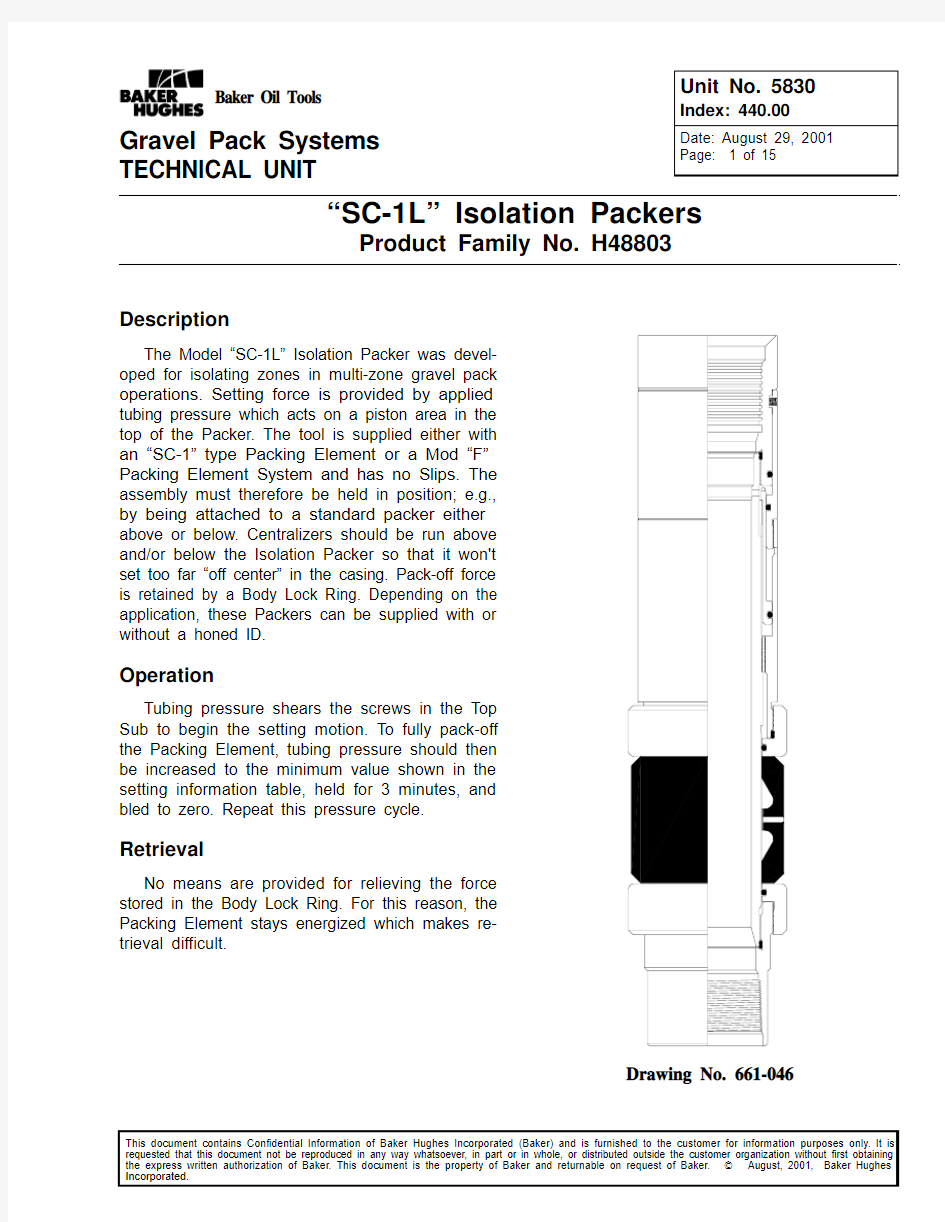
“SC-1L” Isolation Packers
Product Family No. H48803
Description
The Model “SC-1L” Isolation Packer was devel-oped for isolating zones in multi-zone gravel pack operations. Setting force is provided by applied tubing pressure which acts on a piston area in the top of the Packer. The tool is supplied either with an “SC-1” type Packing Element or a Mod “F”Packing Element System and has no Slips. The assembly must therefore be held in position; e.g.,by being attached to a standard packer either above or below. Centralizers should be run above and/or below the Isolation Packer so that it won't set too far “off center” in the casing. Pack-off force is retained by a Body Lock Ring. Depending on the application, these Packers can be supplied with or without a honed ID.
Operation
Tubing pressure shears the screws in the Top Sub to begin the setting motion. To fully pack-off the Packing Element, tubing pressure should then be increased to the minimum value shown in the setting information table, held for 3 minutes, and bled to zero. Repeat this pressure cycle.
Retrieval
No means are provided for relieving the force stored in the Body Lock Ring. For this reason, the Packing Element stays energized which makes re-trieval difficult.
Drawing No. 661-046
WARNING
Use of Baker equipment contrary to manufacturer ’s specification may result in property damage, serious injury or fatality.
Unit No. 5830Index 440.00Page 2 of 15
“SC-1L ” Isolation Packer Specification Guide And Performance Ratings
Casing
Weight Range ID Range Packer Size Max OD Min ID Honed ID Temperature Rating
Pressure Rating
7
32-35 5.992-6.09470A-36 5.812 3.625 3.625250
3,00029 6.148-6.18470B2-36 5.96832-35
5.992-
6.094
70A-40
5.812 4.000(1) 4.0003.975(1)None 26-32
6.039-6.27670A6-40* 5.859 4.000(1) 4.00010,00029 6.148-6.18470B2-40 5.9683,0004.000(1) 4.0003.975(1)None 23-26 6.258-6.366
70B4-40
6.078 4.000(1) 4.0003.975(1)None 20-23 6.180-6.45670B6-40* 6.000 4.000(1) 4.00010,0007-5/8
29.7-33.7 6.765-6.87576A4-36 6.593 3.625 3.6253,000
26.4-29.7 6.852-6.96976B2-36 6.67229.7-33.7 6.680-6.87576B-38* 6.500 3.865None 10,000
9-5/8
58.48.435-8.56096A2-608.281(2) 6.0001,000 Above / 2,000 Below
47-53.5
8.499-8.68196A3-60*8.3196,00047
8.620-8.681
96A4-60
8.440
1,000 Above / 2,000 Below
(2) 6.0005.906
None
43.5-478.602-8.75596A4-60*8.422(2) 6.0006,000408.788-8.83596B-608.608
1,000 Above / 2,000 Below
36-408.788-8.92196B-60*6,000
* Uses “F-1” Packing Element System
(1) Values shown are for packers with standard 4-1/2" or 5" casing threads in the Bottom Sub. Smaller threads may result in a restriction through the Bottom Sub.
(2) Minimum ID through these packers is governed by Bottom Sub ID
“SC-1L ” Isolation Packer Setting Information
Size
Piston Area (Sq In.)
Tripping Pressure (PSI)
Minimum Setting Pressure (PSI)
Equivalent Minimum Setting Force (lbs)
70-36
10.8062640
300032,40070-4070-40*9.5502000250023,90076-3610.8062640300032,40076-38*12.070237036,20096-60
11.0471500
2500
27,600
96-60*
* Uses “F-1” Packing Element System
8-29-01SC-1L Isolation Packer
Unit No. 5830
Index 440.00Page 3 of 15 SC-1L Isolation Packer
Pre-Assembly Inspection
Procedure For All Sizes
1. 1. Verify that the Body (Body Lock Ring Man-
drel for size 76-38* and 96A4/B-60*) has com-munication ports drilled in its upper end. Verify that the Connector Sub (Connector Sub and Guide Ring for size 76-38* and 70-40*, Guide Ring only for 96-60*, and Setting Sleeve only for size 96-60) has vent ports drilled through the wall. Also, verify that notches have been milled in the upper face of the Piston on sizes 70-36, 70-40, 76-40, 70-40* and 76-38*. These drilled holes and notches are necessary to insure proper movement of the setting mechanism when pressure is applied.
2.Place Connector Sub in vise. Do not over tight-
en vise or Connector Sub will egg.
3.Make up Body Lock Ring into Connector Sub
being careful that the sloped flanks of the Body Lock Ring thread are next to the sloped flanks of the buttress thread in the Connector Sub. Be sure that Lock Ring is approximately centered lengthwise within the buttress thread in the Connector Sub.
4.(Size 70-40* only) Make up Guide Ring onto
lower end of Connector Sub.
5.Stab upper end of Body** into lower end of
Connector Sub.
6.(Size 70-36, 70-40, 76-36 and 76-38*) - Slide
Guide Ring onto lower end of Body** and make up to Connector Sub.
7.Hold a board against the lower face of the
Body** and use a hammer to tap the Body** up-ward through the Connector Sub about two inches to check the ratcheting action of the Body Lock Ring.
NOTE: If the assembly fails to ratchet, the Body Lock Ring may have been installed in the wrong direction and must be reversed. Should this be necessary, the Body Lock Ring should be checked very carefully for damage before reinstalling. If any doubt exists as to the usability of the Body Lock Ring, it should be replaced.
8.Tap the top face of the Body** to force the
Body** in the opposite direction to check the holding ability of the Lock Ring.
NOTE: If the Body Lock Ring does not hold, it should be checked to see if it has been installed backwards or if it has been damaged. Replace if necessary.9.Remove Connector Sub, Guide Ring, and Body
Lock Ring from Body**.
NOTE: When removing Body Lock Ring from Connector Sub it may be helpful to use a stiff wire with a small hook bent into the end and pull at a point 180 deg from the split while spreading and pulling Body Lock Ring with Snap Ring Pliers.
* Packer with “F” Packing Element System
** Body Lock Ring Mandrel for sizes 76-38* and 96A3-60* Pre-Assembly Notes
Apply light coating of downhole grease to all O-rings, O-ring pilots and Packing Element sealing surfaces as required during assembly.
Apply copper based or equivalent thread com-pound to all straight threads except for buttress thread on Connector Sub, wicker threads on Body or Body Lock Ring Mandrel, and Body Lock Ring as required during assembly.
Assembly Instructions For
Sizes 70-36, 70-40, And 76-36
1.Install all O-Rings.
2.Place Connector Sub in vise. Install Body Lock
Ring into Connector Sub until Lock Ring is ap-proximately centered lengthwise within the but-tress thread in the Connector Sub.
3.Install Piston into Piston Housing.
4.Make up and tighten Piston Housing to upper
thread of Connector Sub. Remove sub-assem-bly from vise.
5.Place Bottom Sub in vise. Make up Body into
Bottom Sub and tighten with 48" pipe wrench.
6.Slide lower Guide Ring onto Body, make up
and tighten to thread of Bottom Sub.
7.Slide Packing Element over Body until it shoul-
ders on lower Guide Ring.
8.Slide Upper Guide Ring over Body until it shoul-
ders on Packing Element.
9.Stab sub-assembly (from step #4) onto Body
and make up and tighten Upper Guide Ring to Connector Sub by holding back-up on Connec-tor sub assembly. Do not rotate the sub-assem-bly as it is being stabbed or being made up with Upper Guide Ring. This would cause the Body Lock Ring to move out of its proper position.
8-29-01
SC-1L Isolation Packer Unit No. 5830
Index 440.00Page 4 of 15
10.Make up Top Sub to Body and tighten with 48"
pipe wrench. As this joint is made up, the Top Sub will strike the face of the Piston Housing and push the sub-assembly (from step #4) into the proper position. Do not allow the Connector Sub to rotate as the Top Sub / Body joint is made up. A slight gap (approx .12) should re-main between the Guide Ring and the Packing Element.
11.Install shear screws in Piston Housing.
12.Pressure test internally with shop air (60-90 psi)
and check for leaks.
Assembly Instructions For
Size 70-40 With “F” Element
1.Install all O-Rings.
2.Install Filler Ring in Packing Element.
3.Place Connector Sub in vise. Install Body Lock
Ring into Connector Sub until Lock Ring is ap-proximately centered lengthwise within the but-tress thread in the Connector Sub.
4.Make up and tighten Guide Ring onto lower end
of Connector Sub.
5.Install Piston into Piston Housing.
6.Make up and tighten Piston Housing to upper
thread of Connector Sub. Remove sub-assem-bly from vise.
7.Place Bottom Sub in vise. Make up Body into
Bottom Sub and tighten with 48" pipe wrench.
8.Slide Packing Element components (Packing
Element Rings, Cone Rings, and Packing Ele-ment) onto Body. Be sure that split in Cone Ring is 180 degrees from split in adjacent Pack-ing Element Ring.
9.Stab sub-assembly (from step #5) onto Body
until the Guide Ring has just started onto the largest OD (P.E.OD) of the Body. Do not rotate the sub-assembly as it is being stabbed. This would cause the Body Lock Ring to move out of its proper position.
10.Make up Top Sub to Body and tighten with 48"
pipe wrench. As these joints are made up, the Top Sub will strike the face of the Piston Hous-ing and push the sub-assembly (from step #6) into the proper position. Do not allow the Con-nector Sub to rotate as the Top Sub / Body joint is made up. A slight gap (approx .09) should re-
main between each Seal Ring and the Packing Element.
11.Install shear screws in Piston Housing.
12.Pressure test internally with shop air (60-90 psi)
and check for leaks
Assembly Instructions For
Size 76-38 With “F” Element
1.Install all O-Rings.
2.Install Filler Ring in Packing Element.
3.Place Connector Sub in vise. Install Body Lock
Ring into Connector Sub until Lock Ring is ap-proximately centered lengthwise within the but-tress thread in the Connector Sub.
4.Install Piston into Piston Housing.
5.Make up and tighten Piston Housing to upper
thread of Connector Sub.
6.Stab Body Lock Ring Mandrel, ported end first,
into lower end of Connector Sub assembly until wickers on Body Lock Ring Mandrel are just covered by lower end of Connector Sub.
7.Slide Guide Ring onto lower end of Body Lock
Ring Mandrel, make up and tighten to Connec-tor Sub. Do not allow Body Lock Ring Mandrel to rotate. This would cause the Body Lock Ring to move out of proper position.
8.Place Bottom Sub in vise. Make up Body into
Bottom Sub and tighten with 48" pipe wrench.
9.Slide Packing Element components (Packing
Element Rings, Cone Rings, and Packing Ele-ment) onto Body. Be sure that split in Cone Ring is 180 degrees from split in adjacent Pack-ing Element Ring. Remove from vise.
10.With Guide Ring in vice over smaller diameter
O-ring, just tight enough to keep the Body Lock Ring Mandrel from turning, make up Body sub-assembly to lower end of Body Lock Ring Man-drel hand tight. Remove from vise.
11.Place Bottom Sub in vise, make up and tighten
Top Sub to Body Lock Ring Mandrel with 48"
pipe wrench. This will also finish tightening the connection between the Body Lock Ring Man-drel and Body. As these joints are made up, the Top Sub will strike the face of the Piston Hous-ing and push the sub-assembly (from step #6) into the proper position. A slight gap (approx .09) should remain between each Seal Ring and the Packing Element.
8-29-01
Unit No. 5830
Index 440.00Page 5 of 15 SC-1L Isolation Packer
12.Install shear screws in Piston Housing.
13.Pressure test internally with shop air (60-90 psi)
and check for leaks.
Assembly Instructions For Size 96-60
1.Install all O-Rings.
2.Place Connector Sub in vise. Install Body Lock
Ring into Connector Sub until Lock Ring is ap-proximately centered lengthwise within the but-tress thread in the Sub.
3.Make up and tighten upper Gage Ring to lower
end of Connector Sub. Remove sub-assembly from vise.
4.Place Bottom Sub in vise. Make up Body into
Bottom Sub and tighten with 48" pipe wrench.
5.Slide lower Gage Ring onto Body make up and
tighten to thread of Bottom Sub.
6.Slide Packing Element over Body until it shoul-
ders on lower Gage Ring.
7.Stab sub-assembly (from step #3) onto Body
until the O-Ring in the upper Gage Ring has just started onto its sealing surface. Do not rotate the sub-assembly as it is being stabbed. This would cause the Body Lock Ring to move out of its proper position.
8.Make up Top Sub to Body and tighten with 48"
pipe wrench. Do not allow the Connector Sub to rotate as the Top Sub / Body joint is being made up.
9.Slide Setting Sleeve over Top Sub. Hold a
back-up wrench on the Connector Sub while making up and tightening the Setting Sleeve to the Connector Sub. Be careful not to turn the Connector Sub relative to the Body in order to preserve the proper positioning of the Body Lock Ring.
10.Tap the Setting Sleeve downward until the
groove in the Top Sub lines up with the tapped holes in the Setting Sleeve. A slight gap (ap-prox .12) should remain between the Gage Ring and the Packing Element.
11.Install shear screws in the Setting Sleeve.
12.Pressure test internally with shop air (60-90 psi)
and check for leaks.Assembly Instructions For
Size 96-60 With “F” Element
1.Install all O-rings as required.
2.Install Filler Ring in Packing Element.
3.Sub-assemble and tighten Guide Ring onto
Connector Sub. Set sub-assembly aside.
4.Place Bottom Sub in vise.
5.Make up Body into Bottom Sub. Tighten with
strap or chain wrench on smooth OD just above Wickers or on upper end of short (size A4 & B) Body. Do not use pipe wrench on Body.
6.(Sizes A4 and B only) Make up Body Lock Ring
Mandrel to Body.
7.Stand Body Sub Assembly on floor on Bottom
Sub. Install Packing Element System onto Body. Be sure split in Cone Ring is 180 degrees from split in adjacent Packing Element Ring.
8.Thread Body Lock Ring into Connector Sub so
upper end of Body Lock Ring is flush with upper internal face in Connector Sub at Buttress Thread.
9.Slide Connector Sub sub-assembly over BLR
Mandrel/Body carefully working O-ring over threads and wickers. Tap Connector Sub down so Guide Ring is positioned ? - ? inch from Packing Element System.
10.Place assembly in vise at Bottom Sub.
11.With back-up wrench on Guide Ring, make up
Top Sub onto BLR Mandrel/Body. Do not allow Connector Sub/Guide Ring to turn. Tighten Top Sub with 48" pipe wrench.
12.Install Shear Screws. File all wrench marks.
13.Pressure test internally with shop air (60-90 psi)
and check for leaks.
8-29-01
As China is speeding up its modernization drive, and due to its accelerating urbanization process, many people feel isolated from each other. Write a composition of about 400 words on this issue. We are living in a much more crowded world, and the fast development of information technology is making this world unimaginably smaller. Despite all these, a sense of isolation has been growing among people, esp. among the urban dwellers. Here are some of the reasons. First, modern people experience greater tensions so that they have less time to communicate with each other. As more and more people move to the cities, the pace of life is getting exhaustingly fast. Due to the fierce competition, urban residents have to work hard to as to keep up with the steps of city life. Moreover, living in apartments in different blocks, people find it virtually inconvenient to meet and chat with each other as freely as before. Second, the wide use of telephone and the internet prevent people from seeing each other quite often. Face-to-face contact used to be fundamental way to get information. However, technologies today have enormously reduced the necessity of meeting each other, and a felling of isolation arises accordingly. In the past, when a festival came, the way people send congratulations was to meet each other, to get together or write letters and send postcards. Nowadays, people can simply send an E-mail or make a phone call to express good wishes in a few minutes. There are some solutions to the present situation. First of all, people need to be fully aware of the fact that the modern ways of communication cannot replace the traditional ones. Sending #-mails cannot have the same effect as writing or face-to-face talk. Traditional ways should be encouraged and people can write letters as much as possible. Secondly, activities held in one neighborhood can create a warm atmosphere among people. Urbanization refers to a process in which an increasing proportion of an entire population lives in cities and the suburbs of cities. I Structure: -- logical: (cause and effect) 1 Thesis: problem/phenomenon 2 Body: analysis (reasons, examples
总RNA 提取 (SV Total RNA Isolation System Kit,Promega) 1.低于30mg的样品中加入175μl裂解缓冲液(SV RNA Lysis Buffer+ BME),充分匀浆。 2.加入350μl蓝色的RNA 稀释缓冲液(SV RNA Dilution Buffer), 颠倒3-4次使样品充分混合。 3.放入70℃水浴中裂解3min。 注:温育时间不要超过3分钟,否则可能破坏RNA的完整性。 4.14,000g 离心10 min。小心用移液器将上清液转移到新的Eppendorf 管中。 注:①若是组织中脂肪含量较高,需重复几次此步骤;②避免吸到颗粒物。 5.加入95%的乙醇200μl于上清液,用枪头冲吸3-4 次。 6.将其全部转移到带有滤膜的微型柱中,14,000g, 离心1min,弃滤液。 7.加入600μl冲洗缓冲液(SV RNA Wash Solution), 14,000g, 离心1 min,弃滤液。 注:确保SV RNA Wash Solution已用乙醇稀释过。 8.按样品数量准备DNA 酶Ⅰ混合液,用于降解DNA。每样需40μl黄 色缓冲液, 5μl 0.09M的MnCl2和5μl DNA 酶Ⅰ配制的DNA 酶Ⅰ混 合液。 注:①DNA 酶Ⅰ必须在冰上解冻;②温柔用移液器混合,不可涡旋。 9.确保加50μl DNA 酶Ⅰ混合液到滤膜中间,室温保持15 min。 10.加入200μl终止反应缓冲液(SV DNase Stop Solution),14,000g, 离 心1 min,不必弃滤液。 注:确保SV DNase Stop Solution中已加入乙醇。 11.加入600μl 冲洗缓冲液(SV RNA Wash Solution),14,000g,离心 1 分钟,弃滤液。 12.再加入250μl冲洗缓冲液洗一次(SV RNA Wash Solution), 14,000g,离心2 min,弃滤液,转移微型柱到新的洗脱管中。 13.用100μl无RNA酶的水(Nuclease-Free Water)洗膜,14,000g, 离心1min,-70℃保存洗脱下来的总RNA。 注:确保无RNA酶的水覆盖膜表面。
Social Isolation-Definition Imagine what the life would be like if you lived in a place for 30 years and was then stranded completely alone on a deserted island for the rest of your life.(Robinson) And of course, the conclusion is that, social isolation would be horribly lonely for someone used to being around people. Socialization is such a basic part of our lives that it is easy to overlook its importance. But it is the reason we laugh, cry, talk and do many of the other things we think of as just a part of being human. Socialization doesn't always happen, though, and certainly can't happen in social isolation. This is a state that occurs when someone experiences a complete lack of contact with the social world. Further negative effects-cause more harmfull illnesses. So what would you do if you feel yourself in the state of isolation? More eating? Or more drinking? The way we deal with the isolation can become another problems such as overweight and alcohol abuse.
Miltenyi Biotec GmbH Friedrich-Ebert-Stra?e 68, 51429 Bergisch Gladbach, Germany Phone +49 2204 8306-0, Fax +49 2204 85197macs @miltenyibiotec.de https://www.doczj.com/doc/4a2388233.html, Miltenyi Biotec Inc. 2303 Lindbergh Street, Auburn, CA 95602, USA Phone 800 FOR MACS , +1 530 888 8871, Fax +1 530 888 8925macs @https://www.doczj.com/doc/4a2388233.html, page 1/2 140-002-824.06 Components 1 mL Pan T Ce ll Biotin-Antibody Cocktail, mouse: Cocktail of biotin-conjugated monoclonal antibodies against CD11b, CD11c, CD19, CD45R (B220), CD49b (DX5), CD105, Anti-MHC class II, and Ter-119. 2 mL Anti-Biotin MicroBeads: MicroBeads conjugated to monoclonal anti-biotin antibodies (isotype: mouse IgG1). Capacity For 10? total cells, up to 100 separations. Product format All components are supplied in buffer containing stabilizer and 0.05% sodium azide.Storage Store protected from light at 2 ? 8 °C. Do not freeze. The expiration date is indicated on the vial label. Safety information For re se arch use only. Not inte nde d for any animal or human therapeutic or diagnostic use. Be fore use , ple ase consult the Mate rial Safe ty Data She e t for information regarding hazards and safe handling practices. Cell separation methods 1.Fully automated cell labeling and separation using the autoMACS? Pro Separator 2. Manual magnetic labeling 2.1 Subsequent automated cell separation using the autoMACS? Separators 2.2 Subsequent semi-automated cell separation using the MultiMACS? Cell24 Separator Plus 2.3 Subsequent manual cell separation General notes ▲ For an overview of the sample preparation procedure and recommendations for magnetic labeling and separation, refer to https://www.doczj.com/doc/4a2388233.html,/faq.▲ For product-specific background information and applications of this product, refer to the respective product page at https://www.doczj.com/doc/4a2388233.html,/130-095-130.Reagent and instrument requirements ● Buffer: Prepare a solution containing phosphate-buffered saline (PBS), pH 7.2, 0.5% bovine serum albumin (BSA), and 2 mM EDTA by diluting MACS? BSA Stock Solution (# 130-091-376) 1:20 with autoMACS? Rinsing Solution (# 130-091-222). Degas buffer before use, as air bubbles could block the column. ● (Optional) Pre-Separation Filters, 30 μm (# 130-041-407) to remove cell clumps. ● Choose the appropriate MACS Separator and MACS Columns. Column M ax. number of labeled cells Max. number of total cells Separator LS 10? 2 ×10?MidiMACS, QuadroMACS, VarioMACS, SuperMACS II autoMACS 2×10? 4 ×10?autoMACS Pro, autoMACS Multi-24 Column Block 10? 10? MultiMACS Cell24 Separator Plus ▲ Note: If using the MultiMACS Cell24 Separator Plus with the Single-Column Adapter, please refer to the user manual for column capacities. For additional requirements not included with the product, such as instruments or fluorochrome-conjugated antibodies, refer to https://www.doczj.com/doc/4a2388233.html,. 1. Fully automated cell labeling and separation using the autoMACS? Pro Separator ▲ All buffer temperatures should be ≥10 °C. ▲ Place tubes in the following Chill Rack positions:position A = sample, position B = negative fraction, position C = positive fraction.1. For appropriate resuspension volumes and cell concentrations, please visit https://www.doczj.com/doc/4a2388233.html,/autolabeling. 2. Turn on the instrument for automatic initialization. 3. Program autolabeling in the Reagent menu by selecting Read Reagent and scan the 2D barcode of each reagent vial with the barcode scanner on the autoMACS? Pro Separator. Place the reagent into the appropriate space on the reagent rack.4. Place sample and collection tubes into the Chill Rack. Sample tube should be in row A, and the collection tubes in rows B and C. 5. Go to Separation menu and select the reagent name for each sample from the Labeling submenu (the correct labeling, separation, and wash protocols will be selected automatically). 6. Enter sample volume into the Volume submenu. 7. Select run . For more details on complete walk away automation, please refer to the autoMACS Pro Separator user manual. Pan T Cell Isolation Kit II mouse Order no. 130-095-130
Frequently Asked Questions About Vibration What does it mean to isolate vibration? 隔离振动的意思是? Isolation refers to a reduction in transmitted vibratory forces. 隔离是指减少传递振动的力。 How is isolation achieved?隔离如何达到? Isolation is achieved by placing an isolator (elastic element) between the unit vibrating and its support. This allows the inertia of the unit to oppose and thereby reduce the vibratory motion transmitted to the support. 隔离通过放置一个减震器(弹性装置)在振动单元和支撑物之间达到。这就让装置惯性反对从而减少振动传递到支撑物。 What characteristics must an isolator have?减震器有什么性能? An isolator must be (and remain) elastic for the life of the installation. It must have the capacity to support the static weight of the unit as well as the unbalanced dynamic force. It must have a natural frequency lower than the offending unit's disturbing frequency. 减震器必须(并且保持)有弹性在使用寿命内。不但有能力必须支持装置的静重,而且能支持不稳定的动态力。它的自然频率必须比引起干扰装置的干扰频率低。 How do we determine the natural frequency of an isolator?如何确定减震 器的自然频率? The natural frequency of an isolator is determined by the following mathematical relationship: 减震器的自然频率可以通过以下的数学关系式确定: Where: K D = Dynamic Spring Rate, lb/in动态弹性系数 W = Static Weight of the Isolated Unit, lb减震器的的静重 Isolator manufacturers have this information readily available in their publications.减震器的制造商可以容易获得现成的资料在他们的出版物中。What natural frequency should an isolator have?减震器的自然频率是多 少? It depends on the desired percent reduction in transmitted vibration, referred to as transmissibility, and is governed by the ratio of disturbing frequency to isolator natural frequency. The larger this ratio, the greater the reduction. Isolation begins at a ratio of 1.414. 这个取决于在传递振动中期望衰减的百分比,称之为传递率,并且是由干扰频率对减震器自然频率的比值。比值越大,衰减的越大从比值1.414开始。
在隔离人时,除了可以用isolation 表隔离,quarantine 也可以表示隔离,但它们隔离的性质不一样。 一、isolation 表示将病人与其他健康的人分开,避免健康的人受到感染。如果一个人主动要求隔离叫做self-isolation。通常与介词in 连用,它的动词形式是isolate. This patient needs to be in isolation for a week. 这个病人要隔离1周。 Several houses have been isolated by the flood water; A child with an infectious disease should be isolated. 有几所房子被洪水隔离了;有传染病的孩子应该隔离。 二、quarantine 表示隔离一群健康的人,看他们是否在以后出现症状并避免进一步传播,这些人接触过传染性疾病。像isolation 一样,一个人也可以主动要求quarantine,叫做self-quarantine,它的动词形式与名词同形。 She was sent home to Oxford and put in quarantine. 她被送回牛津的家中隔离起来。 The health officials placed the ship's crew in quarantine. 卫生官员将该船的全体船员隔离,进行检疫。 quarantine 还可以用来隔离动物,例如: The dog was kept in quarantine for six months. 这条狗被检疫隔离了六个月。 三、它们的区别 1、isolation 把病人跟健康的人分开,而quarantine 涉及到健康人的隔离。 2、isolation 是为了避免健康的人受到感染,而quarantine 用来检查接触过传染病的健康的人是否会生病且避免疾病的传播。 3、被isolated 的人经常是感染疾病的人,而被quarantined 的可能已经生病或没生病。 4、在医院里isolation 是防止疾病爆发的例行程序,而quarantine 只有在有大批量已暴露在某种疾病的人出现时采取的政策。
Total Exosome RNA and Protein Isolation Kit 总论:对于提取exosome RNA用于测序的样品,源于细胞上清的液体应不少于5ml,来源于血清的样品应不少于200ul。 Isolate exosomes with ExoQuick-TC 1.收集新鲜细胞培养上清10ml,3000 × g离心15min去除细胞碎片; 2.转移上清到一无菌15ml离心管,加入2ml ExoQuick-TC试剂,颠倒混匀后4°C放置过 夜; 3.将上清与ExoQuick-TC试剂混合液分成两管后,4°C 、1500 × g离心30 min, exosome 沉于管底; 4.将管4°C 、1500 × g再离心5 min,完全吸走上清; 5.按接下来的实验选择合适的缓冲液100μl - 500μl。 Procedure 准备工作: 2-巯基乙醇(14.3M),无水乙醇/ACS,PBS,10,000xg以上离心机,加热器100°C,真空抽滤泵,RNase-free处理的管/枪头。 2X Denaturing Solution 向2X Denaturing Solution中加入375ul 2-巯基乙醇,注意:2X Denaturing Solution在2°C 到8°C可能会凝固,在使用前37°C预热5-10min,边热边摇,直到完全溶解,并做好标记。miRNA Wash Solution 1 往miRNA Wash Solution 1中加入21ml无水乙醇,充分混匀后,做好标记 Wash Solution 2/3 向Wash Solution 2/3中加入40 ml无水乙醇,混匀做好标记,注意:此溶液中可能会出现沉淀,使用时避免吸取沉淀即可。 聚集exosome沉淀与重悬 1.用预冷的Exosome Resuspension Buffer重悬exosome沉淀,加入的量由exosome量来 决定,可以从25 μL 到1 mL; 2.室温下,孵育5-10 min使exosome充分溶解,装入RNase-free EP管中; 3.小心吹打,充分重悬沉淀,溶解好后,进行RNA抽提或者直接用于蛋白抽提工作; 4.若同时进行RNA的抽提和蛋白实验,把样品分成两份,先提RNA(注意计量吸取 exosome的体积),用于蛋白那份可先放-200C冰箱冻存。 Isolate RNA –Organic extraction
所有试剂用前均须充分混匀, 所有tip均用RNA级 在超净台内无菌操作(做分子生物学实验勿开风机), TotalRNA抽提流程—(SV Total RNA Isolation System,promage Cat# Z3100) 细胞(1.5×10³-5×10⁶)或组织(<30mg)放入1.5mleppendorf中(总体积<1.2ml,Ep管DNA级消毒级即可) 300g离心5’(室温) 用冰浴、无菌PBS洗涤一次,300g离心5’,弃上清(倒) (用过火灭菌镊开盖)加入175μl Lysis buffer(冰浴的,(已加BME)悬空加,勿碰管壁),充分vortex至变清为止,用力颠倒混匀后,用力甩(若组织标本至此步后样本可臵-80℃保存) 2ml针筒抽吸4-5次(以打断DNA)(不同样本,换注射器) 加入(悬空加,否则换tip)350μl Dilution buffer(蓝色)(用前混匀液体,敲盖让液体下去) 颠倒混匀后于70℃水浴3’(不能超过3’,否则易降解;但也不能少于3’,否则总RNA释放不完全,导致得率下降——OD260值低以及重复性差) 离心12000-14000g,室温10’ 吸取上清移至另一eppendorf(从此步起,必须RNA级)中(避免吸取沉淀,有时在液体顶层会有一层固形物,可用tip将其拨开后再吸取上清) 加入200μl 95%乙醇(分装后臵-20℃,用RNA级Ep管保存),吸打4-5次,混匀 将液体移入分离柱中
离心12000-14000g 1’后,将下层漏出液(蓝色)弃去 加入600μl Wash solution(混匀,敲) 离心12000-14000g 1’后,将下层漏出液弃去 加入(看好,直接加在膜上,勿加至壁上)冰浴的DNA酶体系(40μl buffer (黄色,4℃贮存,其实室温即可)+5μlMncl2+5μlDNase(0.2mlEp管分装, -20℃贮存,用前短时离心),(按顺序加,Dnase的融化始终在冰浴上进行,Mncl2和Dnase要分开放,临用前再混匀,轻轻吸打混匀,不要vortex) 臵于室温(20—25℃)15’ 加入200μl Dnase stop solution 离心12000-14000g 1’,弃去下层液 加入600μl Wash solution 离心12000-14000g 1’,弃去下层液 加入250μl Wash solution 离心12000-14000g 2’,弃去下层管及液体 将新eppendorf(RNA级,试剂盒提供)管放于分离柱下,加入100μlRNasefree(-20℃贮存)水12000-14000g 2’ a将溶解的RNA存于-80℃。(不主张以小于100微升的水来进行洗脱,如需要高浓度的RNA,可将其真空干燥后,再重悬于较小体积的水中。)(如有必要,还可将另一根新的eppendorf管放于分离柱下,加100μlRNasefree水再离心一次,第二次的洗涤可再获得相当于总量的10%—20%的RNA。)
PART 2 BIOCHEMICAL PHARMACEUTICALS 生化制药 Unit 6 Isolation of Caffeine from Tea 从茶叶中分离咖啡因 In this experiment, Caffeine will be isolated from tea leaves. 在这个实验中,咖啡因会从茶叶中分离出来。 The major problem of the isolation is that caffeine does not occur alone in tea leaves, but is accompanied by other natural substances from which it must be separated. 分离过程中的主要问题就是,茶叶中不仅仅只有咖啡因,还伴随着需要被分离除去的其他天然物质。 The major component of tea leaves is cellulose,which is the major structural material of all plant cells. 茶叶中的主要成分是所有植物细胞中的主要结构材料——纤维素。 Cellulose is a polymer of glucose. 纤维素是葡萄糖的聚合物。 Since cellulose is virtually insoluble in water, it presents no problems in the isolation procedure. 然而纤维素实际上是不溶于水的,所以在隔离的程序上不用考虑去除纤维素。 Caffeine, on the other hand, is water soluble and is one of the major substances extract ed into the solution called "tea”. 另一方面,咖啡因是水溶性的,也是萃取到溶液(也就是茶)里的主要物质之一。 Caffeine comprise s as much as 5 percent by weight of the leaf material in tea plants. 咖啡因包含了茶树叶片材料总重的5%之多。 Tannins also dissolve in the hot water used to extract tea leaves. 丹宁(鞣酸)也溶解于用于萃取茶叶的热水中。 The term tannin does not refer to a single homogeneous compound, or even to substances which have similar chemical structure. 丹宁一词不是指单个均一的化合物,也不是具有相似化学结构的物质。 It refers to a class of compounds which have certain properties in common. 它是指某些具有共同属性的化合物的种类。 Tannins are phenolic compounds having molecular weights between 500 and 3000. 丹宁是一类分子质量在500到3000的含酚的化合物。 They are widely used to "tan” leather. 它们被广泛用于鞣革。 They precipitate alkaloids and proteins from aqueous solutions. 它们从水溶液中沉淀出生物碱和蛋白质 Tannins are usually divided into two classes: those which can be hydrolyzed and those which cannot. 丹宁通常被分为两类:可水解和不可水解。 Tannins of the first type which are found in tea generally yield glucose and gallic acid when
Isolation of nuclei Working solution for isolation of nuclei (A) Recommended diluent: 150 mM KCl, 30 mM MgCl2 120 mM Tricine/NaOH, pH 7.8 (to make 100 ml: 1.12 g KCl, 0.61 g MgCl2, 2.16 g Tricine) Density: 1.017 g/ml Refractive index: 1.3400 Osmolality: 530 mOsm Mix 5 parts OptiPrep with 1 part diluent Concentration: 50% (w/v) Iodixanol Density: 1.269 g/ml Refractive index: 1.4148 Osmolality: 320 mOsm Further dilution of the working solution should be made with the following buffer: Diluent A for the preparation of nuclei; 8% (wv) Sucrose, 25 mM KCl, 5 mM MgCl2, 20 mM Tricine/NaOH, pH 7.8 (to make 100 ml: 8 g sucrose, 0.18 g KCl, 0.1 g MgCl2, 0.36 g Tricine) Density: 1.033 g/ml Refractive index: 1.3468 Osmolality: 350 mOsm Equition for dilution: Vd + V1d1 = (V + V1)d2 Rinse cells three times with ice-cooled PBS Add 0.5 ml Diluent A for the preparation of nuclei (containing mini EDTA free protease inhibitor tablets, 10 ml/1 tablet) to each 60-mm culture dish, scrap cells and transfer to a Dounce glass homogenizer. Take one drop to microscope slide. Break cell membrane by 15 strokes, take one drop cell suspension and examine cells with phase-contrast microscope. If see unbroken cells, give more strokes (usually no more than 30 strokes). Spin cell suspension at 2000 g (5000 rpm) at 4 ?C for 10 min. Wash crud nuclei pallet with 1 ml of Diluent A for the preparation of nuclei. The pallet was resuspended in 25% Iodixanol and layered on a discontinuous iodixanol gradient (30 and 35%). Centrifuge in a SW41 swing bucket rotor at 10,000 x g (12500 rpm) for 20 min at 4 ?. Collect nuclei in the interface of 30 and 35% gradient.
Shallow trench isolation Scaling of isolation with transistor size.Isolation pitch is the sum of the transistor width and the trench isolation distance.As the isolation pitch shrinks,the narrow channel width e?ect be-comes more apparent. Shallow trench isolation(STI),also known as Box Isolation Technique,is an integrated circuit feature which prevents electrical current leakage between adja-cent semiconductor device components.STI is gener-ally used on CMOS process technology nodes of250 nanometers and smaller.Older CMOS technologies and non-MOS technologies commonly use isolation based on LOCOS.[1] STI is created early during the semiconductor device fab-rication process,before transistors are formed.The key steps of the STI process involve etching a pattern of trenches in the silicon,depositing one or more dielectric materials(such as silicon dioxide)to?ll the trenches,and removing the excess dielectric using a technique such as chemical-mechanical planarization. Certain semiconductor fabrication technologies also in-clude deep trench isolation,a related feature often found in analog integrated circuits. The e?ect of the trench edge has given rise to what has re-cently been termed the“reverse narrow channel e?ect”[2] or“inverse narrow width e?ect”.[3]Basically,due to the electric?eld enhancement at the edge,it is easier to form a conducting channel(by inversion)at a lower voltage. The threshold voltage is e?ectively reduced for a nar-rower transistor width.[4][5]The main concern for elec-tronic devices is the resulting subthreshold leakage cur-rent,which is substantially larger after the threshold volt-age reduction. 1Process?ow ?Stack deposition(oxide+protective nitride) ?Lithography print ?Dry etch ?Trench?ll with oxide ?Chemical-mechanical polishing of the oxide ?Removal of the protective nitride ?Adjusting the oxide height to Si 2References [1]Quirk,Michael&Julian Serda(2001).Semiconductor Manufacturing Technology:Instructor’s Manual,p.25. [2]J-W.Jung et al.,Jpn.J.Appl.Phys.,39,2136-2140 (2000). [3] A.Chatterjee et al.,IEDM1996. [4]J.Pretet et al.,Solid-State Electronics,46,1699-1707 (2002). [5]Y-H.Lee et al.,Microelectronics Reliability,41,689-696 (2001). 3See also ?FEOL 4External links ?Clarycon:Shallow trench isolation ?N and K Technologies:Shallow trench isolation ?Dow Corning:Spin on Dielectrics-Spin-on Shallow Trench Isolation 1