
C o
n ?d e
n t i a l
f o r I n
n o r
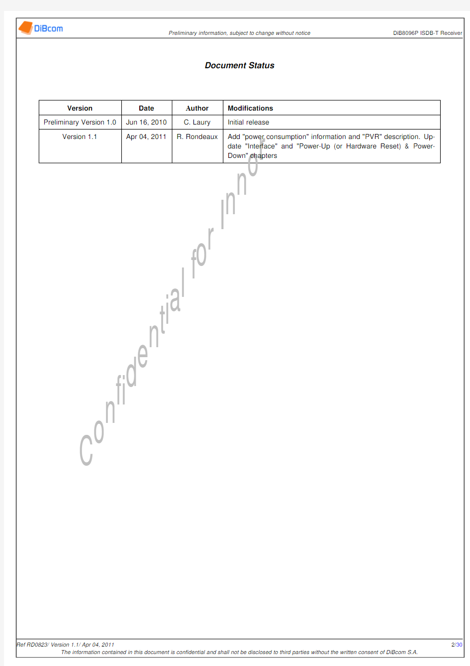
Document Status
Version
Date Author Modi?cations Preliminary Version 1.0
Jun 16,2010 https://www.doczj.com/doc/3615339772.html,ury Initial release
Version 1.1
Apr 04,2011
R.Rondeaux
Add "power consumption"information and "PVR"description.Up-date "Interface"and "Power-Up (or Hardware Reset)&Power-Down"chapters
C o
n ?d e
n t i a l
f o r I n
n o r
Table of contents
Table of contents 3List of Figures 5List of Tables 61Description 72Features 73Applications
74Package
84.1Package Marking ...............
.....................................104.1.11st line:DiBcom logo ..............................................104.1.22nd line:Part Designator ............................................104.1.33rd line:Product version identi?cation .....................................104.1.44th line:Wafer lot traceability ..........................................104.1.55th line:Traceability information .....
.........................
..........
105IOs Banks
116Operating conditions
126.1Power supplies characteristics .............................................126.2ESD characteristics ..................................................126.3Thermal information ..................................................126.4Power consumption .....
...
..........................................
13
7IOs Electrical Speci?cation 147.1DC Speci?cations of Multi-Voltage I/O Buffers Operating under 3.3V .........................147.2DC Speci?cations of Multi-Voltage I/O Buffers Operating under 2.5V .........................147.3DC Speci?cations of Multi-Voltage I/O Buffers Operating under 1.8V . (14)
8Pins Description
169Functional Description
189.1Architecture Overview .................................................189.2Digital and sampling clocks ..............
................................199.2.1Power-Up (or Hardware Reset)&Power-Down ................................199.2.2Implementation dependent constraints .....................................199.2.3PLL .......................................................209.2.4ADC clock generator block ...........................................209.3RF T uner ........................
................................219.3.1Block Diagram .................................................219.3.2RXRF ......................................................219.3.3Mixer ......................................................229.3.4Baseband ....................................................229.3.5LO ........................................................229.3.6Crystal Oscillator (22)
C o
n ?d e
n t i a l
f o r I n
n o r
9.3.8ADC .......................................................229.4Demodulator ...................
...................................239.4.1ADC .......................................................239.4.2Analog AGC ..................................................239.4.3IQ Impairment Compensation .........................................239.4.4Surrounding noise compensation ........................................239.4.5Base band frequency offset compensation ...................................239.4.6Interpolation and Filtering ............................................239.4.7Guard time removal ...............................................239.4.8FFT .......................................................239.4.9Diversity combiner ...............................................239.4.10De-interleaving .................................................249.4.11Viterbi Decoder .................................................249.4.12Auxiliary Channel ................................................249.4.13FEC .......................................................249.4.14TMCC ......................................................259.4.15Synchronization control .............................................2510Interfaces
2610.1Host Interface ......................................................2610.2Single MPEG2-TS Interface ...........
...................................2710.2.1T ransport stream parallel output ........................................2710.2.2T ransport stream serial output .........................................2710.3Dual MPEG2-TS Interface ............
...................................2710.3.1Parallel mode ..................................................2810.3.2Serial mode ...................................................2810.4Diversity &PVR interface .............
...................................2810.4.1Diversity .....................................................2810.4.2Personnal Video Recorder (PVR)interface ...................................2810.4.3interface Information ..............................................2910.4.4General purpose input/output interface ..
...
..........
......................
29
C o
n ?d e
n t i a l
f o r I n
n o r
List of Figures
4.1DiB8096P pinout ...................................................84.2Package information .................................................99.1Functional block diagram ...............................................189.2power up and down sequence ............................................199.3RF T uner Block Diagram ...............................................219.4Diversity connectivity .....
....
........................................2410.1Parallel MPEG2output with gated clock using 188bytes output mode .......................2710.2Parallel MPEG2output with gated clock using 204bytes output mode .......................2710.3MPEG2serial output mode ..............................................2710.4MPEG2Dual TS parallel output ...........................................2810.5MPEG2Dual TS serial output ............................................2810.6PVR connectivity Two MPEG2-TS ..........................................2910.7PVR connectivity Dual MPEG2-TS ..........................................2910.8
Diversity IC chain clock distribution ...................
.
.
.
.
.
.
.
.
.
.
.
.
.
.
.
.
.
.
.
.
.
.
.
29
C o
n ?d e
n t i a l
f o r I n
n o r
List of Tables
6.2Power Supplies Characteristics ............................................126.4ESD characteristics ..................................................126.6Thermal information .................................................126.8DiB8096P Power Consumption
............
..........
(13)
8.2Pins description ....................................................179.2Required Crystal Speci?cation ............................................199.4ADC clock range when derived directly from the external clock ...........................209.6ADC and digital clocks derived from reference ....................................209.8VHF Input Characteristics ..............................................219.10UHF Input Characteristics ..............................................2210.3HOST_BUS mapping .................................................2610.5Diversity outputs mapping ..............................................2910.7DiB8096P I 2C Addresses ...............................................2910.9
GPIOs functional mapping
......
.............
(30)
C o
n ?d e
n t i a l
f o r I n
n o r
The package mechanical data are presented in the following ?gures:
Figure 4.2:Package information
The re?ow process of the DiB8096P follows Pb-free process of the IPC/JEDEC J-STD-020D.1standard as presented below:
Pro?le Feature Pb-Free assembly T smin 150?C T smax 200?C t s 60-120s T L 217?C t L 60-150s T p 260?C t p
30s max Time 25?C to Peak 8min max Re?ow count per device
3max