MT9P401: 1/2.5-Inch 5Mp Digital Image Sensor
Features
Micron Confidential and Proprietary
Advance ?
PDF: 09005aef82acb06f/Source: 09005aef82acb9d0Micron Technology, Inc., reserves the right to change products or specifications without notice.
MT9P401_DS_1.fm -Rev. A 4/07 EN
?2007 Micron Technology, Inc. All rights reserved.
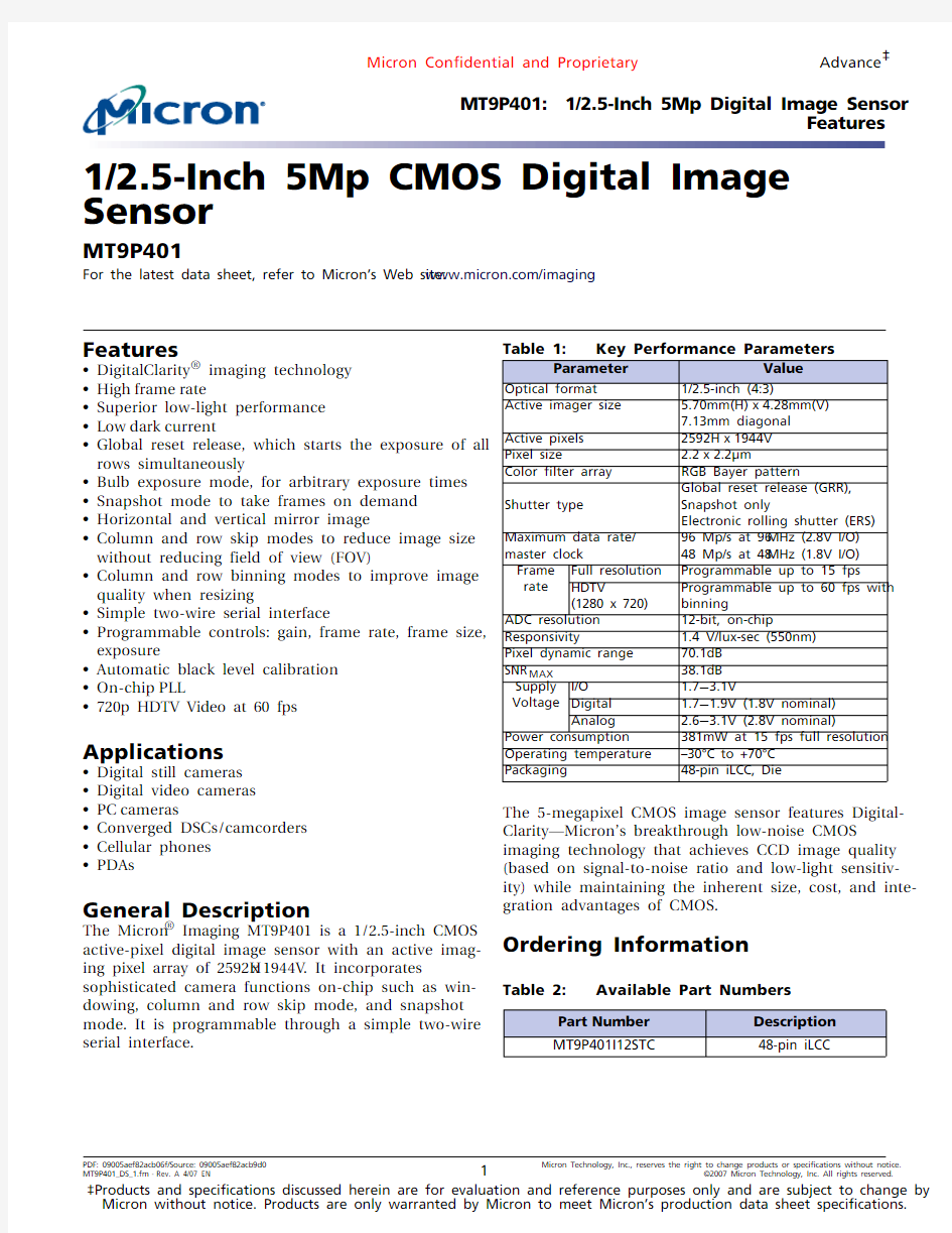
1/2.5-Inch 5Mp CMOS Digital Image Sensor
MT9P401
For the latest data sheet, refer to Micron’s Web site: https://www.doczj.com/doc/315677814.html,/imaging
Features
?DigitalClarity ? imaging technology
?High frame
rate
?Superior low-light performance ?Low dark current
?Global reset release, which starts the exposure of all rows simultaneously
?Bulb exposure mode, for arbitrary exposure times ?Snapshot mode to take frames on demand ?Horizontal and vertical mirror image
?Column and row skip modes to reduce image size
without reducing field of view (FOV)
?Column and row binning modes to improve image quality when resizing
?Simple two-wire serial interface
?Programmable controls: gain, frame rate, frame size, exposure
?Automatic black level calibration ?On-chip PLL
?
720p HDTV Video at 60 fps
Applications
?Digital still cameras ?Digital video cameras ?PC
cameras
?Converged DSCs/camcorders ?Cellular phones ?
PDAs
General Description
The Micron ? Imaging MT9P401 is a 1/2.5-inch CMOS active-pixel digital image sensor with an active imag-ing pixel array of 2592H x 1944V . It incorporates
sophisticated camera functions on-chip such as win-dowing, column and row skip mode, and snapshot mode. It is programmable through a simple two-wire serial interface.
Table 1: Key Performance Parameters
The 5-megapixel CMOS image sensor features Digital-Clarity—Micron’s breakthrough low-noise CMOS imaging technology that achieves CCD image quality (based on signal-to-noise ratio and low-light sensitiv-ity) while maintaining the inherent size, cost, and inte-gration advantages of CMOS.
Ordering Information
Parameter
Value
Optical format 1/2.5-inch (4:3)
Active imager size 5.70mm(H)x 4.28mm(V)7.13mm diagonal Active pixels 2592H x 1944V Pixel size
2.2x 2.2μm
Color filter array RGB Bayer pattern
Shutter type
Global reset release (GRR), Snapshot only
Electronic rolling shutter (ERS)Maximum data rate/master clock
96 Mp/s at 96MHz (2.8V I/O)48 Mp/s at 48MHz (1.8V I/O)Frame rate Full resolution Programmable up to 15 fps
HDTV
(1280 x 720)
Programmable up to 60 fps with binning
ADC resolution 12-bit, on-chip
Responsivity
1.4 V/lux-sec (550nm)Pixel dynamic range 70.1dB SNR MAX
38.1dB Supply Voltage I/O 1.7?3.1V
Digital
1.7?1.9V (1.8V nominal)Analog
2.6?
3.1V (2.8V nominal)
Power consumption 381mW at 15 fps full resolution Operating temperature –30°C to +70°C Packaging
48-pin iLCC, Die
Table 2:
Available Part Numbers
Part Number Description MT9P401I12STC
48-pin iLCC
Table of Contents
Features. . . . . . . . . . . . . . . . . . . . . . . . . . . . . . . . . . . . . . . . . . . . . . . . . . . . . . . . . . . . . . . . . . . . . . . . . . . . . . . . . . . . . . . . . . . . . .1 Applications . . . . . . . . . . . . . . . . . . . . . . . . . . . . . . . . . . . . . . . . . . . . . . . . . . . . . . . . . . . . . . . . . . . . . . . . . . . . . . . . . . . . . . . . . .1 General Description . . . . . . . . . . . . . . . . . . . . . . . . . . . . . . . . . . . . . . . . . . . . . . . . . . . . . . . . . . . . . . . . . . . . . . . . . . . . . . . . . . .1 Ordering Information. . . . . . . . . . . . . . . . . . . . . . . . . . . . . . . . . . . . . . . . . . . . . . . . . . . . . . . . . . . . . . . . . . . . . . . . . . . . . . . . . .1 General Description . . . . . . . . . . . . . . . . . . . . . . . . . . . . . . . . . . . . . . . . . . . . . . . . . . . . . . . . . . . . . . . . . . . . . . . . . . . . . . . . . . .6 Functional Overview. . . . . . . . . . . . . . . . . . . . . . . . . . . . . . . . . . . . . . . . . . . . . . . . . . . . . . . . . . . . . . . . . . . . . . . . . . . . . . . . . . .6 Pixel Data Format . . . . . . . . . . . . . . . . . . . . . . . . . . . . . . . . . . . . . . . . . . . . . . . . . . . . . . . . . . . . . . . . . . . . . . . . . . . . . . . . . . . .10 Pixel Array Structure . . . . . . . . . . . . . . . . . . . . . . . . . . . . . . . . . . . . . . . . . . . . . . . . . . . . . . . . . . . . . . . . . . . . . . . . . . . . . . .10 Default Readout Order . . . . . . . . . . . . . . . . . . . . . . . . . . . . . . . . . . . . . . . . . . . . . . . . . . . . . . . . . . . . . . . . . . . . . . . . . . . . .11 Output Data Format (Default Mode). . . . . . . . . . . . . . . . . . . . . . . . . . . . . . . . . . . . . . . . . . . . . . . . . . . . . . . . . . . . . . . . .12 Readout Sequence . . . . . . . . . . . . . . . . . . . . . . . . . . . . . . . . . . . . . . . . . . . . . . . . . . . . . . . . . . . . . . . . . . . . . . . . . . . . . . . . .12 Output Data Timing . . . . . . . . . . . . . . . . . . . . . . . . . . . . . . . . . . . . . . . . . . . . . . . . . . . . . . . . . . . . . . . . . . . . . . . . . . . . . . . . . .14 LINE_VALID and FRAME_VALID . . . . . . . . . . . . . . . . . . . . . . . . . . . . . . . . . . . . . . . . . . . . . . . . . . . . . . . . . . . . . . . . . . . .14 LINE_VALID Format Options. . . . . . . . . . . . . . . . . . . . . . . . . . . . . . . . . . . . . . . . . . . . . . . . . . . . . . . . . . . . . . . . . . . . .14 Frame Time . . . . . . . . . . . . . . . . . . . . . . . . . . . . . . . . . . . . . . . . . . . . . . . . . . . . . . . . . . . . . . . . . . . . . . . . . . . . . . . . . . . . . . .15 Frame Rates at Common Resolutions . . . . . . . . . . . . . . . . . . . . . . . . . . . . . . . . . . . . . . . . . . . . . . . . . . . . . . . . . . . . . . . .16 Serial Bus Description . . . . . . . . . . . . . . . . . . . . . . . . . . . . . . . . . . . . . . . . . . . . . . . . . . . . . . . . . . . . . . . . . . . . . . . . . . . . . . . .18 Protocol . . . . . . . . . . . . . . . . . . . . . . . . . . . . . . . . . . . . . . . . . . . . . . . . . . . . . . . . . . . . . . . . . . . . . . . . . . . . . . . . . . . . . . . . . .18 Sequence . . . . . . . . . . . . . . . . . . . . . . . . . . . . . . . . . . . . . . . . . . . . . . . . . . . . . . . . . . . . . . . . . . . . . . . . . . . . . . . . . . . . . . . . .18 Bus Idle State. . . . . . . . . . . . . . . . . . . . . . . . . . . . . . . . . . . . . . . . . . . . . . . . . . . . . . . . . . . . . . . . . . . . . . . . . . . . . . . . . . . . . .18 Start Bit. . . . . . . . . . . . . . . . . . . . . . . . . . . . . . . . . . . . . . . . . . . . . . . . . . . . . . . . . . . . . . . . . . . . . . . . . . . . . . . . . . . . . . . . . . .18 Stop Bit. . . . . . . . . . . . . . . . . . . . . . . . . . . . . . . . . . . . . . . . . . . . . . . . . . . . . . . . . . . . . . . . . . . . . . . . . . . . . . . . . . . . . . . . . . .19 Slave Address. . . . . . . . . . . . . . . . . . . . . . . . . . . . . . . . . . . . . . . . . . . . . . . . . . . . . . . . . . . . . . . . . . . . . . . . . . . . . . . . . . . . . .19 Data Bit Transfer. . . . . . . . . . . . . . . . . . . . . . . . . . . . . . . . . . . . . . . . . . . . . . . . . . . . . . . . . . . . . . . . . . . . . . . . . . . . . . . . . . .19 Acknowledge Bit. . . . . . . . . . . . . . . . . . . . . . . . . . . . . . . . . . . . . . . . . . . . . . . . . . . . . . . . . . . . . . . . . . . . . . . . . . . . . . . . . . .19 No-Acknowledge Bit . . . . . . . . . . . . . . . . . . . . . . . . . . . . . . . . . . . . . . . . . . . . . . . . . . . . . . . . . . . . . . . . . . . . . . . . . . . . . . .19 Two-Wire Serial Interface Sample Write and Read Sequences. . . . . . . . . . . . . . . . . . . . . . . . . . . . . . . . . . . . . . . . . . . . .20 16-Bit Write Sequence. . . . . . . . . . . . . . . . . . . . . . . . . . . . . . . . . . . . . . . . . . . . . . . . . . . . . . . . . . . . . . . . . . . . . . . . . . . . . .20 16-Bit Read Sequence . . . . . . . . . . . . . . . . . . . . . . . . . . . . . . . . . . . . . . . . . . . . . . . . . . . . . . . . . . . . . . . . . . . . . . . . . . . . . .20 Registers . . . . . . . . . . . . . . . . . . . . . . . . . . . . . . . . . . . . . . . . . . . . . . . . . . . . . . . . . . . . . . . . . . . . . . . . . . . . . . . . . . . . . . . . . . . .21 Register List . . . . . . . . . . . . . . . . . . . . . . . . . . . . . . . . . . . . . . . . . . . . . . . . . . . . . . . . . . . . . . . . . . . . . . . . . . . . . . . . . . . . . . .21 Register Description . . . . . . . . . . . . . . . . . . . . . . . . . . . . . . . . . . . . . . . . . . . . . . . . . . . . . . . . . . . . . . . . . . . . . . . . . . . . . . .26 Features. . . . . . . . . . . . . . . . . . . . . . . . . . . . . . . . . . . . . . . . . . . . . . . . . . . . . . . . . . . . . . . . . . . . . . . . . . . . . . . . . . . . . . . . . . . . .37 Reset . . . . . . . . . . . . . . . . . . . . . . . . . . . . . . . . . . . . . . . . . . . . . . . . . . . . . . . . . . . . . . . . . . . . . . . . . . . . . . . . . . . . . . . . . . . . .37 Hard Reset . . . . . . . . . . . . . . . . . . . . . . . . . . . . . . . . . . . . . . . . . . . . . . . . . . . . . . . . . . . . . . . . . . . . . . . . . . . . . . . . . . . . . . . .37 Soft Reset . . . . . . . . . . . . . . . . . . . . . . . . . . . . . . . . . . . . . . . . . . . . . . . . . . . . . . . . . . . . . . . . . . . . . . . . . . . . . . . . . . . . . . . . .37 Power Up and Power Down. . . . . . . . . . . . . . . . . . . . . . . . . . . . . . . . . . . . . . . . . . . . . . . . . . . . . . . . . . . . . . . . . . . . . . . . .37 Clocks . . . . . . . . . . . . . . . . . . . . . . . . . . . . . . . . . . . . . . . . . . . . . . . . . . . . . . . . . . . . . . . . . . . . . . . . . . . . . . . . . . . . . . . . . . . .37 PLL-Generated Master Clock. . . . . . . . . . . . . . . . . . . . . . . . . . . . . . . . . . . . . . . . . . . . . . . . . . . . . . . . . . . . . . . . . . . . . . . .38 PLL Setup. . . . . . . . . . . . . . . . . . . . . . . . . . . . . . . . . . . . . . . . . . . . . . . . . . . . . . . . . . . . . . . . . . . . . . . . . . . . . . . . . . . . . . . . .38 Standby and Chip Enable. . . . . . . . . . . . . . . . . . . . . . . . . . . . . . . . . . . . . . . . . . . . . . . . . . . . . . . . . . . . . . . . . . . . . . . . . . .39 Full-Array Readout. . . . . . . . . . . . . . . . . . . . . . . . . . . . . . . . . . . . . . . . . . . . . . . . . . . . . . . . . . . . . . . . . . . . . . . . . . . . . . . . .39 Window Control . . . . . . . . . . . . . . . . . . . . . . . . . . . . . . . . . . . . . . . . . . . . . . . . . . . . . . . . . . . . . . . . . . . . . . . . . . . . . . . . . . .40 Readout Modes. . . . . . . . . . . . . . . . . . . . . . . . . . . . . . . . . . . . . . . . . . . . . . . . . . . . . . . . . . . . . . . . . . . . . . . . . . . . . . . . . . . .40 Subsampling. . . . . . . . . . . . . . . . . . . . . . . . . . . . . . . . . . . . . . . . . . . . . . . . . . . . . . . . . . . . . . . . . . . . . . . . . . . . . . . . . . . .40 Skipping. . . . . . . . . . . . . . . . . . . . . . . . . . . . . . . . . . . . . . . . . . . . . . . . . . . . . . . . . . . . . . . . . . . . . . . . . . . . . . . . . . . . . . . .40 Binning . . . . . . . . . . . . . . . . . . . . . . . . . . . . . . . . . . . . . . . . . . . . . . . . . . . . . . . . . . . . . . . . . . . . . . . . . . . . . . . . . . . . . . . .42 Mirror . . . . . . . . . . . . . . . . . . . . . . . . . . . . . . . . . . . . . . . . . . . . . . . . . . . . . . . . . . . . . . . . . . . . . . . . . . . . . . . . . . . . . . . . . . . .44 Column Mirror Image. . . . . . . . . . . . . . . . . . . . . . . . . . . . . . . . . . . . . . . . . . . . . . . . . . . . . . . . . . . . . . . . . . . . . . . . . . . .44 Row Mirror Image . . . . . . . . . . . . . . . . . . . . . . . . . . . . . . . . . . . . . . . . . . . . . . . . . . . . . . . . . . . . . . . . . . . . . . . . . . . . . . .44 Maintaining a Constant Frame Rate . . . . . . . . . . . . . . . . . . . . . . . . . . . . . . . . . . . . . . . . . . . . . . . . . . . . . . . . . . . . . . . . .45
Synchronizing Register Writes to Frame Boundaries. . . . . . . . . . . . . . . . . . . . . . . . . . . . . . . . . . . . . . . . . . . . . . . . . . .45 Restart. . . . . . . . . . . . . . . . . . . . . . . . . . . . . . . . . . . . . . . . . . . . . . . . . . . . . . . . . . . . . . . . . . . . . . . . . . . . . . . . . . . . . . . . . . . .46 Image Acquisition Modes. . . . . . . . . . . . . . . . . . . . . . . . . . . . . . . . . . . . . . . . . . . . . . . . . . . . . . . . . . . . . . . . . . . . . . . . . . .46 Electronic Rolling Shutter . . . . . . . . . . . . . . . . . . . . . . . . . . . . . . . . . . . . . . . . . . . . . . . . . . . . . . . . . . . . . . . . . . . . . . . .46 Global Reset Release. . . . . . . . . . . . . . . . . . . . . . . . . . . . . . . . . . . . . . . . . . . . . . . . . . . . . . . . . . . . . . . . . . . . . . . . . . . . .47 Exposure. . . . . . . . . . . . . . . . . . . . . . . . . . . . . . . . . . . . . . . . . . . . . . . . . . . . . . . . . . . . . . . . . . . . . . . . . . . . . . . . . . . . . . . . . .47 Operating Modes . . . . . . . . . . . . . . . . . . . . . . . . . . . . . . . . . . . . . . . . . . . . . . . . . . . . . . . . . . . . . . . . . . . . . . . . . . . . . . . . . .48 Strobe Control . . . . . . . . . . . . . . . . . . . . . . . . . . . . . . . . . . . . . . . . . . . . . . . . . . . . . . . . . . . . . . . . . . . . . . . . . . . . . . . . . .50 Signal Chain and Datapath . . . . . . . . . . . . . . . . . . . . . . . . . . . . . . . . . . . . . . . . . . . . . . . . . . . . . . . . . . . . . . . . . . . . . . . . .51 Gain . . . . . . . . . . . . . . . . . . . . . . . . . . . . . . . . . . . . . . . . . . . . . . . . . . . . . . . . . . . . . . . . . . . . . . . . . . . . . . . . . . . . . . . . . . .51 Analog Gain . . . . . . . . . . . . . . . . . . . . . . . . . . . . . . . . . . . . . . . . . . . . . . . . . . . . . . . . . . . . . . . . . . . . . . . . . . . . . . . . . . . .52 Digital Gain. . . . . . . . . . . . . . . . . . . . . . . . . . . . . . . . . . . . . . . . . . . . . . . . . . . . . . . . . . . . . . . . . . . . . . . . . . . . . . . . . . . . .52 Offset . . . . . . . . . . . . . . . . . . . . . . . . . . . . . . . . . . . . . . . . . . . . . . . . . . . . . . . . . . . . . . . . . . . . . . . . . . . . . . . . . . . . . . . . . .52 Analog Black Level Calibration. . . . . . . . . . . . . . . . . . . . . . . . . . . . . . . . . . . . . . . . . . . . . . . . . . . . . . . . . . . . . . . . . . . .52 Digital Black Level Calibration. . . . . . . . . . . . . . . . . . . . . . . . . . . . . . . . . . . . . . . . . . . . . . . . . . . . . . . . . . . . . . . . . . . .53 Test Patterns . . . . . . . . . . . . . . . . . . . . . . . . . . . . . . . . . . . . . . . . . . . . . . . . . . . . . . . . . . . . . . . . . . . . . . . . . . . . . . . . . . . . . .53 Classic Test Pattern. . . . . . . . . . . . . . . . . . . . . . . . . . . . . . . . . . . . . . . . . . . . . . . . . . . . . . . . . . . . . . . . . . . . . . . . . . . . . .54 Color Field. . . . . . . . . . . . . . . . . . . . . . . . . . . . . . . . . . . . . . . . . . . . . . . . . . . . . . . . . . . . . . . . . . . . . . . . . . . . . . . . . . . . . .54 Vertical Color Bars. . . . . . . . . . . . . . . . . . . . . . . . . . . . . . . . . . . . . . . . . . . . . . . . . . . . . . . . . . . . . . . . . . . . . . . . . . . . . . .54 Horizontal Gradient . . . . . . . . . . . . . . . . . . . . . . . . . . . . . . . . . . . . . . . . . . . . . . . . . . . . . . . . . . . . . . . . . . . . . . . . . . . . .54 Vertical Gradient . . . . . . . . . . . . . . . . . . . . . . . . . . . . . . . . . . . . . . . . . . . . . . . . . . . . . . . . . . . . . . . . . . . . . . . . . . . . . . . .54 Diagonal Gradient. . . . . . . . . . . . . . . . . . . . . . . . . . . . . . . . . . . . . . . . . . . . . . . . . . . . . . . . . . . . . . . . . . . . . . . . . . . . . . .54 Marching 1's. . . . . . . . . . . . . . . . . . . . . . . . . . . . . . . . . . . . . . . . . . . . . . . . . . . . . . . . . . . . . . . . . . . . . . . . . . . . . . . . . . . .54 Monochrome Vertical Bars . . . . . . . . . . . . . . . . . . . . . . . . . . . . . . . . . . . . . . . . . . . . . . . . . . . . . . . . . . . . . . . . . . . . . . .54 Monochrome Horizontal Bars . . . . . . . . . . . . . . . . . . . . . . . . . . . . . . . . . . . . . . . . . . . . . . . . . . . . . . . . . . . . . . . . . . . .54 Spectral Characteristics. . . . . . . . . . . . . . . . . . . . . . . . . . . . . . . . . . . . . . . . . . . . . . . . . . . . . . . . . . . . . . . . . . . . . . . . . . . . . . .55 Electrical Specifications. . . . . . . . . . . . . . . . . . . . . . . . . . . . . . . . . . . . . . . . . . . . . . . . . . . . . . . . . . . . . . . . . . . . . . . . . . . . . . .56 Two-Wire Serial Register Interface. . . . . . . . . . . . . . . . . . . . . . . . . . . . . . . . . . . . . . . . . . . . . . . . . . . . . . . . . . . . . . . . . . .56 I/O Timing. . . . . . . . . . . . . . . . . . . . . . . . . . . . . . . . . . . . . . . . . . . . . . . . . . . . . . . . . . . . . . . . . . . . . . . . . . . . . . . . . . . . . . . .57 DC Electrical Characteristics. . . . . . . . . . . . . . . . . . . . . . . . . . . . . . . . . . . . . . . . . . . . . . . . . . . . . . . . . . . . . . . . . . . . . . . .59 Package Dimensions . . . . . . . . . . . . . . . . . . . . . . . . . . . . . . . . . . . . . . . . . . . . . . . . . . . . . . . . . . . . . . . . . . . . . . . . . . . . . . . . .61 Revision History. . . . . . . . . . . . . . . . . . . . . . . . . . . . . . . . . . . . . . . . . . . . . . . . . . . . . . . . . . . . . . . . . . . . . . . . . . . . . . . . . . . . . .62
List of Figures
Figure 1:Block Diagram. . . . . . . . . . . . . . . . . . . . . . . . . . . . . . . . . . . . . . . . . . . . . . . . . . . . . . . . . . . . . . . . . . . . . . . . . . . .6 Figure 2:Typical Configuration (Connection) . . . . . . . . . . . . . . . . . . . . . . . . . . . . . . . . . . . . . . . . . . . . . . . . . . . . . . . .7 Figure 3:48-Pin iLCC 10x10 Package Pinout Diagram (Top View). . . . . . . . . . . . . . . . . . . . . . . . . . . . . . . . . . . . . . .8 Figure 4:Pixel Array Description . . . . . . . . . . . . . . . . . . . . . . . . . . . . . . . . . . . . . . . . . . . . . . . . . . . . . . . . . . . . . . . . . . .11 Figure 5:Pixel Color Pattern Detail (Top Right Corner) . . . . . . . . . . . . . . . . . . . . . . . . . . . . . . . . . . . . . . . . . . . . . . .11 Figure 6:Imaging a Scene . . . . . . . . . . . . . . . . . . . . . . . . . . . . . . . . . . . . . . . . . . . . . . . . . . . . . . . . . . . . . . . . . . . . . . . . .12 Figure 7:Spatial Illustration of Image Readout. . . . . . . . . . . . . . . . . . . . . . . . . . . . . . . . . . . . . . . . . . . . . . . . . . . . . . .12 Figure 8:Default Pixel Output Timing . . . . . . . . . . . . . . . . . . . . . . . . . . . . . . . . . . . . . . . . . . . . . . . . . . . . . . . . . . . . . .14 Figure 9:LINE_VALID Format Options. . . . . . . . . . . . . . . . . . . . . . . . . . . . . . . . . . . . . . . . . . . . . . . . . . . . . . . . . . . . . .15 Figure 10:Frame Timing . . . . . . . . . . . . . . . . . . . . . . . . . . . . . . . . . . . . . . . . . . . . . . . . . . . . . . . . . . . . . . . . . . . . . . . . . . .15 Figure 11:Timing Diagram Showing a Write to R0x09 with the Value 0x0284. . . . . . . . . . . . . . . . . . . . . . . . . . . . .20 Figure 12:Timing Diagram Showing a Read from R0x09; Returned Value 0x0284 . . . . . . . . . . . . . . . . . . . . . . . . .20 Figure 13:PLL Generated Master Clock . . . . . . . . . . . . . . . . . . . . . . . . . . . . . . . . . . . . . . . . . . . . . . . . . . . . . . . . . . . . . .38 Figure 14:Eight Pixels in Normal and Column Skip 2X Readout Modes. . . . . . . . . . . . . . . . . . . . . . . . . . . . . . . . . .40 Figure 15:Pixel Readout (no skipping) . . . . . . . . . . . . . . . . . . . . . . . . . . . . . . . . . . . . . . . . . . . . . . . . . . . . . . . . . . . . . . .41 Figure 16:Pixel Readout (Column Skip 2X) . . . . . . . . . . . . . . . . . . . . . . . . . . . . . . . . . . . . . . . . . . . . . . . . . . . . . . . . . . .41 Figure 17:Pixel Readout (Row Skip 2X). . . . . . . . . . . . . . . . . . . . . . . . . . . . . . . . . . . . . . . . . . . . . . . . . . . . . . . . . . . . . . .42 Figure 18:Pixel Readout (Column Skip 2X, Row Skip 2X). . . . . . . . . . . . . . . . . . . . . . . . . . . . . . . . . . . . . . . . . . . . . . .42 Figure 19:Pixel Readout (Column Bin 2X). . . . . . . . . . . . . . . . . . . . . . . . . . . . . . . . . . . . . . . . . . . . . . . . . . . . . . . . . . . .43 Figure 20:Pixel Readout (Column Bin 2X, Row Bin 2X) . . . . . . . . . . . . . . . . . . . . . . . . . . . . . . . . . . . . . . . . . . . . . . . .44 Figure 21:Six Pixels in Normal and Column Mirror Readout Modes. . . . . . . . . . . . . . . . . . . . . . . . . . . . . . . . . . . . .44 Figure 22:Six Rows in Normal and Row Mirror Readout Modes . . . . . . . . . . . . . . . . . . . . . . . . . . . . . . . . . . . . . . . .44 Figure 23:ERS Snapshot Timing. . . . . . . . . . . . . . . . . . . . . . . . . . . . . . . . . . . . . . . . . . . . . . . . . . . . . . . . . . . . . . . . . . . . .49 Figure 24:GRR Snapshot Timing . . . . . . . . . . . . . . . . . . . . . . . . . . . . . . . . . . . . . . . . . . . . . . . . . . . . . . . . . . . . . . . . . . . .50 Figure 25:Signal Path . . . . . . . . . . . . . . . . . . . . . . . . . . . . . . . . . . . . . . . . . . . . . . . . . . . . . . . . . . . . . . . . . . . . . . . . . . . . . .51 Figure 26:Typical Spectral Characteristics . . . . . . . . . . . . . . . . . . . . . . . . . . . . . . . . . . . . . . . . . . . . . . . . . . . . . . . . . . .55 Figure 27:CRA versus Image Height . . . . . . . . . . . . . . . . . . . . . . . . . . . . . . . . . . . . . . . . . . . . . . . . . . . . . . . . . . . . . . . . .55 Figure 28:Two-Wire Serial Bus Timing Parameters. . . . . . . . . . . . . . . . . . . . . . . . . . . . . . . . . . . . . . . . . . . . . . . . . . . .56 Figure 29:I/O Timing Diagram. . . . . . . . . . . . . . . . . . . . . . . . . . . . . . . . . . . . . . . . . . . . . . . . . . . . . . . . . . . . . . . . . . . . . .58 Figure 30:48-Pin iLCC Package Outline Drawing. . . . . . . . . . . . . . . . . . . . . . . . . . . . . . . . . . . . . . . . . . . . . . . . . . . . . .61
List of Tables
Table 1:Key Performance Parameters. . . . . . . . . . . . . . . . . . . . . . . . . . . . . . . . . . . . . . . . . . . . . . . . . . . . . . . . . . . . . . .1 Table 2:Available Part Numbers. . . . . . . . . . . . . . . . . . . . . . . . . . . . . . . . . . . . . . . . . . . . . . . . . . . . . . . . . . . . . . . . . . . .1 Table 3:Pin Description . . . . . . . . . . . . . . . . . . . . . . . . . . . . . . . . . . . . . . . . . . . . . . . . . . . . . . . . . . . . . . . . . . . . . . . . . . .8 Table 4:Pixel Type by Column . . . . . . . . . . . . . . . . . . . . . . . . . . . . . . . . . . . . . . . . . . . . . . . . . . . . . . . . . . . . . . . . . . . .10 Table 5:Pixel Type by Row. . . . . . . . . . . . . . . . . . . . . . . . . . . . . . . . . . . . . . . . . . . . . . . . . . . . . . . . . . . . . . . . . . . . . . . .10 Table 6:Dark Rows Sampled as a Function of Row_Bin . . . . . . . . . . . . . . . . . . . . . . . . . . . . . . . . . . . . . . . . . . . . . .13 Table 7:Dark Columns Sampled as a Function of Column_Bin . . . . . . . . . . . . . . . . . . . . . . . . . . . . . . . . . . . . . . .13 Table 8:Frame Time . . . . . . . . . . . . . . . . . . . . . . . . . . . . . . . . . . . . . . . . . . . . . . . . . . . . . . . . . . . . . . . . . . . . . . . . . . . . .16 Table 9:HBmin Values for Row_bin vs. Column_bin Settings. . . . . . . . . . . . . . . . . . . . . . . . . . . . . . . . . . . . . . . . .16 Table 10:Standard Resolutions. . . . . . . . . . . . . . . . . . . . . . . . . . . . . . . . . . . . . . . . . . . . . . . . . . . . . . . . . . . . . . . . . . . . .16 Table 11:Wide Screen (16:9) Resolutions. . . . . . . . . . . . . . . . . . . . . . . . . . . . . . . . . . . . . . . . . . . . . . . . . . . . . . . . . . . .17 Table 12:Register List and Default Values . . . . . . . . . . . . . . . . . . . . . . . . . . . . . . . . . . . . . . . . . . . . . . . . . . . . . . . . . . .21 Table 13:Register Description. . . . . . . . . . . . . . . . . . . . . . . . . . . . . . . . . . . . . . . . . . . . . . . . . . . . . . . . . . . . . . . . . . . . . .26 Table 14:Legal Values for Column_Skip Based on Column_Bin. . . . . . . . . . . . . . . . . . . . . . . . . . . . . . . . . . . . . . . .43 Table 15:Operating Modes . . . . . . . . . . . . . . . . . . . . . . . . . . . . . . . . . . . . . . . . . . . . . . . . . . . . . . . . . . . . . . . . . . . . . . . .48 Table 16:STROBE Timepoints. . . . . . . . . . . . . . . . . . . . . . . . . . . . . . . . . . . . . . . . . . . . . . . . . . . . . . . . . . . . . . . . . . . . . .50 Table 17:Gain Increment Settings . . . . . . . . . . . . . . . . . . . . . . . . . . . . . . . . . . . . . . . . . . . . . . . . . . . . . . . . . . . . . . . . . .51 Table 18:Test Pattern Modes. . . . . . . . . . . . . . . . . . . . . . . . . . . . . . . . . . . . . . . . . . . . . . . . . . . . . . . . . . . . . . . . . . . . . . .53 Table 19:Two-Wire Serial Bus Characteristics (fsio_000 cell) . . . . . . . . . . . . . . . . . . . . . . . . . . . . . . . . . . . . . . . . . .57 Table 20:I/O Timing Characteristics. . . . . . . . . . . . . . . . . . . . . . . . . . . . . . . . . . . . . . . . . . . . . . . . . . . . . . . . . . . . . . . .58 Table 21:DC Electrical Characteristics . . . . . . . . . . . . . . . . . . . . . . . . . . . . . . . . . . . . . . . . . . . . . . . . . . . . . . . . . . . . . .59 Table 22:Power Consumption . . . . . . . . . . . . . . . . . . . . . . . . . . . . . . . . . . . . . . . . . . . . . . . . . . . . . . . . . . . . . . . . . . . . .60 Table 23:Absolute Maximum Ratings. . . . . . . . . . . . . . . . . . . . . . . . . . . . . . . . . . . . . . . . . . . . . . . . . . . . . . . . . . . . . . .60
General Description
The sensor can be operated in its default mode or programmed by the user for frame
size, exposure, gain setting, and other parameters. The default mode outputs a full reso-
lution image at 15 frames per second (fps).
An on-chip analog-to-digital converter (ADC) provides 12 bits per pixel. FRAME_VALID
and LINE_VALID signals are output on dedicated pins, along with a pixel clock that is
synchronous with valid data.
The MT9P401 produces extraordinarily clear, sharp digital pictures, and its ability to
capture both continuous HDTV video and single frames makes it the perfect choice for a
wide range of consumer and digital video cameras.
Functional Overview
The MT9P401 is a progressive-scan sensor that generates a stream of pixel data at a
constant frame rate. It uses an on-chip, phase-locked loop (PLL) to generate all internal
clocks from a single master input clock running between 6and 27MHz. The maximum
pixel rate is 96 Mp/s, corresponding to a clock rate of 96MHz. Figure1 illustrates a block
diagram of the sensor.
Figure 1: Block Diagram
User interaction with the sensor is through the two-wire serial bus, which communi-
cates with the array control, analog signal chain, and digital signal chain. The core of the
sensor is a 5Mp active-pixel array. The timing and control circuitry sequences through
the rows of the array, resetting and then reading each row in turn. In the time interval
between resetting a row and reading that row, the pixels in the row integrate incident
light. The exposure is controlled by varying the time interval between reset and readout.
Once a row has been read, the data from the columns is sequenced through an analog
signal chain (providing offset correction and gain), and then through an ADC. The
output from the ADC is a 12-bit value for each pixel in the array. The ADC output passes
through a digital processing signal chain (which provides further data path corrections
and applies digital gain). The pixel data are output at a rate of up to 96Mp/s, in addition
to frame and line synchronization signals.
Figure 2: Typical Configuration (Connection)
Notes: 1.Resistor value 1.5KΩ is recommended, but may be greater for slower two-wire speed.
2.All power supplies should be adequately decoupled.
3.All D GND pins must be tied together, as must all A GND pins, all V DD IO pins, and all V DD pins.
Figure 3: 48-Pin iLCC 10x10 Package Pinout Diagram (Top View)
Table 3: Pin Description
Name Type Description
RESET_BAR Input When LOW, the MT9P401 asynchronously resets. When driven HIGH, it resumes
normal operation with all configuration registers set to factory defaults.
EXTCLK Input External input clock.
SCLK Input Serial clock. Pull to V DD IO with a 1.5KΩresistor.
OE_BAR Input When HIGH, the PIXCLK, D OUT, FRAME_VALID, LINE_VALID, and STROBE outputs
enter a High-Z. When driven LOW, normal operation resumes.
STANDBY#Input Standby. When LOW, the chip enters a low-power standby mode. It resumes
normal operation when the pin is driven HIGH.
TRIGGER Input Snapshot trigger. Used to trigger one frame of output in snapshot modes, and to
indicate the end of exposure in bulb exposure modes.
S ADDR Input Serial address. When HIGH, the MT9P401 responds to device ID (BA)H. When LOW,
it responds to serial device ID (90)H.
S DATA I/O Serial data. Pull to V DD IO with a 1.5KΩresistor.
PIXCLK Output Pixel clock. The D OUT, FRAME_VALID, LINE_VALID, and STROBE outputs should be
captured on the falling edge of this signal.
D OUT[11:0]Output Pixel data. Pixel data is 12-bit. MSB (D OUT11) through LSB (D OUT0) of each pixel, to
be captured on the falling edge of PIXCLK.
FRAME_VALID Output Frame valid. Driven HIGH during active pixels and horizontal blanking of each
frame and LOW during vertical blanking.
LINE_VALID Output Line valid. Driven HIGH with active pixels of each line and LOW during blanking
periods.
Table 3: Pin Description (continued)
Name Type Description
STROBE Output Snapshot strobe. Driven HIGH when all pixels are exposing in snapshot modes.
V DD Supply Digital supply voltage. Nominally 1.8V.
V DD IO Supply IO supply voltage. Nominally 1.8 or 2.8V.
D GND Supply Digital ground.
V AA Supply Analog supply voltage. Nominally 2.8V.
VAAPIX Supply Pixel supply voltage. Nominally 2.8V, connected externally to V AA.
A GND Supply Analog ground.
V DD PLL Supply PLL supply voltage. Nominally 2.8V, connected externally to V AA.
TEST—Tie to A GND for normal device operation (factory use only).
RSVD—Tie to D GND for normal device operation (factory use only).
NC—No connect.
Pixel Data Format
Pixel Array Structure
The MT9P401 pixel array consists of a 2752-column by 2,004-row matrix of pixels
addressed by column and row. The address (column 0, row 0) represents the upper-right
corner of the entire array, looking at the sensor, as shown in Figure4.
The array consists of a 2592-column by 1944-row active region in the center representing
the default output image, surrounded by a boundary region (also active), surrounded by
a border of dark pixels (see Table4 and Table5). The boundary region can be used to
avoid edge effects when doing color processing to achieve a 2,592 x 1,944 result image,
while the optically black column and rows can be used to monitor the black level.
Pixels are output in a Bayer pattern format consisting of four “colors”—Green1, Green2,
Red, and Blue (G1, G2, R, B)—representing three filter colors. When no mirror modes are
enabled, the first row output alternates between G1 and R pixels, and the second row
output alternates between B and G2 pixels. The Green1 and Green2 pixels have the same
color filter, but they are treated as separate colors by the data path and analog signal
chain.
Table 4: Pixel Type by Column
Column Pixel Type
0–9Dark (10)
10–15Active boundary (6)
16–2,607Active image (2592)
2,608–2,617Active boundary (10)
2,618–2,751Dark (134)
Table 5: Pixel Type by Row
Row Pixel Type
0– 49Dark (50)
50–53Active boundary (4)
54–1997Active image (1944)
1,998–2,001Active boundary (3)
2,002–2003Dark (2)
Figure 4: Pixel Array Description
Figure 5: Pixel Color Pattern Detail (Top Right Corner)
Default Readout Order
By convention, the sensor core pixel array is shown with pixel (0,0) in the top right
corner (see Figure4). This reflects the actual layout of the array on the die. Also, the first
pixel data read out of the sensor in default condition is that of pixel (16,54).
When the sensor is imaging, the active surface of the sensor faces the scene as shown in
Figure6 on page12. When the image is read out of the sensor, it is read one row at a time,
with the rows and columns sequenced as shown in Figure5.
Figure 6: Imaging a Scene
Output Data Format (Default Mode)
The MT9P401 image data is read out in a progressive scan. Valid image data is
surrounded by horizontal blanking and vertical blanking, as shown in Figure7.
LINE_VALID is HIGH during the shaded region of the figure. FRAME_VALID timing is
described in “Output Data Timing” on page14.
Figure 7: Spatial Illustration of Image Readout
Readout Sequence
Typically, the readout window is set to a region including only active pixels. The user has
the option of reading out dark regions of the array, but if this is done, consideration must
be given to how the sensor reads the dark regions for its own purposes.
Rows are read from the array in the following order:
1.Dark rows:
If Show_Dark_Rows is set, or if Manual_BLC is clear, dark rows on the top of the array
is read out. The set of rows sampled are adjusted based on the Row_Bin setting such
that there are 8 rows after binning, as shown in the Table6.
The Row_Skip setting is ignored for the dark row region.
If Show_Dark_Rows is clear and Manual_BLC is set, no dark rows are read from the array
as part of this step, allowing all rows to be part of the active image. This does not change
the frame time, as H DR is included in the vertical blank period.
2.Active image:
The rows defined by the row start, row size, bin, skip, and row mirror settings are read
out. If this set of rows includes rows read out above, those rows are resampled, mean-
ing that the data is invalid.
Table 6: Dark Rows Sampled as a Function of Row_Bin
Row_Bin H DR (Dark Rows After Binning)
08
18
38
Columns are read out in the following order:
1.Dark columns:
If either Show_Dark_Columns or Row_BLC is set, dark columns on the left side of the
image is read out followed by those on the right side. The set of columns read is shown
in Table7.
The Column_Skip setting is ignored for the dark columns.
If neither Show_Dark_Columns nor Row_BLC is set, no dark columns are read, allowing
all columns to be part of the active image. This does not change the row time, as W DC is
included in the vertical blank period.
2.Active image:
The columns defined by column start, column size, bin, skip, and column mirror set-
tings are read out. If this set of columns includes the columns read out above, these
columns are resampled, meaning the data is invalid.
Table 7: Dark Columns Sampled as a Function of Column_Bin
Column_Bin W DC(Dark Columns After Binning)
080
140
320
Output Data Timing
The output images are divided into frames, which are further divided into lines. By default, the sensor produces 1944 rows of 2592 columns each. The FRAME_VALID and LINE_VALID signals indicate the boundaries between frames and lines, respectively. PIXCLK can be used as a clock to latch the data. For each PIXCLK cycle, one 12-bit pixel datum outputs on the D OUT pins. When both FRAME_VALID and LINE_VALID are
asserted, the pixel is valid. PIXCLK cycles that occur when FRAME_VALID is negated are called vertical blanking. PIXCLK cycles that occur when only LINE_VALID is negated are called horizontal blanking.
Figure 8:
Default Pixel Output Timing
LINE_VALID and FRAME_VALID
The timing of the FRAME_VALID and LINE_VALID outputs is closely related to the row time and the frame time.
The FRAME_VALID pin will be asserted for an integral number of row times, which will normally be equal to the height of the output image. If Show_Dark_Rows is set, the dark sample rows will be output before the active image, and FRAME_VALID will be extended to include them. In this case, FRAME_VALID 's leading edge happens at time 0.
The LINE_VALID pin will be asserted during the valid pixels of each row. The leading edge of LINE_VALID will be offset from the leading edge of FRAME_VALID by
609PIXCLKs. If Show_Dark_Columns is set, the dark columns will be output before the image pixels, and LINE_VALID will be extended back to include them; in this case, the first pixel of the active image still occurs at the same position relative to the leading edge of FRAME_VALID. Normally, LINE_VALID will only be asserted if FRAME_VALID is asserted; this is configurable as described below.
LINE_VALID Format Options
The default situation is for LINE_VALID to be negated when FRAME_VALID is negated. The other option available is shown in Figure 9 on page 15. If Continuous_LINE_VALID is set, LINE_VALID is asserted even when FRAME_VALID is not, with the same period and duty cycle. If XOR_Line_Valid is set, but not Continuous_Line_Valid, the resulting LV will be the XOR of FV and the continuous LV
.
Figure 9: LINE_VALID Format Options
The timing of an entire frame is shown in Figure10.
Figure 10: Frame Timing
Frame Time
The pixel clock (PIXCLK) represents the time needed to sample 1 pixel from the array,
and is typically equal to 1 EXTCLK period. The sensor outputs data at the maximum rate
of 1 pixel per PIXCLK. One row time (t ROW) is the period from the first pixel output in a
row to the first pixel output in the next row. The row time and frame time are defined by
equations in Table8 on page16.
The minimum horizontal blanking (HB MIN ) values for various Row_Bin and Column_Bin settings are shown in Table 9.
Frame Rates at Common Resolutions
Table 10 and Table 11 on page 17 show examples of register settings to achieve common resolutions and their frame rates. Frame rates are shown both with subsampling enabled and disabled.
Table 8:
Frame Time
Parameter Name
Equation
Default Timing at EXTCLK =96MHz
fps
Frame Rate 1/t FRAME
14t FRAME Frame Time (H + max(VB, VB MIN )) × t ROW
71.66ms t
ROW_Default
Row Time 2 × t PIXCLK x max(((W/2) + max(HB, HB MIN )), (41 + 346 x
(Row_Bin+1) + 99))
36.38μs t
ROW_HDTV
Row Time
2 × t PIXCLK x max(((W/2) + max(HB, HB MIN )), (41 + 186 x
(Row_Bin+1) + 99))
24.4μs W Output Image Width 2 × ceil((Column_Size + 1) / (2 × (Column_Skip + 1)))
2592 PIXCLK H Output Image Height 2 × ceil((Row_Size + 1) / (2 × (Row_Skip + 1)))
1944 rows SW Shutter Width max(1, (2*16 × Shutter_Width_Upper)
+ Shutter_Width_Lower)1943 rows HB Horizontal Blanking Horizontal_Blank + 1 1 PIXCLK VB Vertical Blanking
Vertical_Blank + 1
26 rows HB MIN Minimum Horizontal Blanking
346 × (Row_Bin + 1) + 64 + (W DC /2)
450 PIXCLK VB MIN
Minimum Vertical Blanking max(8, SW - H) + 1
9 rows t PIXCLK
Pixclk Period
1/f PIXCLK
10.42ns
Table 9:
HB MIN Values for Row_bin vs. Column_bin Settings
Column_bin (W DC )Row_bin
013
045043042017967767663
14881468
1458
Table 10:
Standard Resolutions
Resolution
Frame Rate
Sub-sampling Mode
Column_Size (R0x04)Row_Size (R0x03)Shutter_ Width_Lower (R0x09)Row_Bin (R0x22[5:4])Row_Skip (R0x22[2:0])Column_Bin (R0x23[5:4])Column_Skip (R0x23[2:0])
2592 x 1944(Full Resolution)
14N/A 25911943<194300002,048 x 1,536 QXGA 21N/A 20471535<153500001,600 x 1,200 UXGA 31
N/A
1599
1199
<1199
Notes:
1.It is assumed that the minimum horizontal blanking and the minimum vertical blanking conditions are met, and that all other registers are set to default values. Please refer to TN09111 for instructions on how to configure 720p HDTV.
1,280 x 1,024 SXGA 42N/A 12791023<10230
0001,024 x 768 XGA
63N/A 1023767<767
000063skipping 20471535010147binning 204715351111800 x 600 SVGA 90N/A 799599<599
000090skipping 15991199010165binning 159911********* x 480 VGA 123N/A 639479<479
0000123skipping 25591919030353
binning
2559
1919
3
3
3
3
Table 11: Wide Screen (16:9) Resolutions
Resolution Frame Rate Sub-sampling Mode Column_Size (R0x04)Row_Size (R0x03)Shutter_ Width_Lower (R0x09)Row_Bin (R0x22[5:4])Row_Skip (R0x22[2:0])Column_Bin (R0x23[5:4])Column_Skip (R0x23[2:0])
1,920 x 1,080 HDTV 31N/A 19191079<107900001,280 x 720 HDTV
60
binning
2559
1439
<719
1
1
1
1
Table 10:
Standard Resolutions (continued)
Resolution Frame Rate Sub-sampling Mode Column_Size (R0x04)Row_Size (R0x03)Shutter_ Width_Lower (R0x09)Row_Bin (R0x22[5:4])Row_Skip (R0x22[2:0])Column_Bin (R0x23[5:4])Column_Skip (R0x23[2:0])
Serial Bus Description
Registers are written to and read from the MT9P401 through the two-wire serial interface
bus. The MT9P401 is a serial interface slave and is controlled by the serial clock (SCLK),
which is driven by the serial interface master. Data is transferred into and out of the
MT9P401MT9P401 through the serial data (S DATA) line. The S DATA line is pulled up to
V DD IO off-chip by a 1.5KΩ resistor. Either the slave or master device can pull the S DATA
line LOW—the serial interface protocol determines which device is allowed to pull the
S DATA line down at any given time.
Protocol
The two-wire serial defines several different transmission codes, as follows:
?a start bit
?the slave device 8-bit address
?an acknowledge or a no-acknowledge bit
?an 8-bit message
?a stop bit
Sequence
A typical read or write sequence begins by the master sending a start bit. After the start
bit, the master sends the slave device's 8-bit address. The last bit of the address deter-
mines if the request is a read or a write, where a “0” indicates a write and a “1” indicates
a read. The slave device acknowledges its address by sending an acknowledge bit back to
the master.
If the request was a write, the master then transfers the 8-bit register address to which a
write should take place. The slave sends an acknowledge bit to indicate that the register
address has been received. The master then transfers the data 8 bits at a time, with the
slave sending an acknowledge bit after each 8 bits. The MT9P401 uses 16-bit data for its
internal registers, thus requiring two 8-bit transfers to write to one register. After 16 bits
are transferred, the register address is automatically incremented, so that the next 16 bits
are written to the next register address. The master stops writing by sending a start or
stop bit.
A typical read sequence is executed as follows. First the master sends the write-mode
slave address and 8-bit register address, just as in the write request. The master then
sends a start bit and the read-mode slave address. The master then clocks out the
register data 8 bits at a time. The master sends an acknowledge bit after each 8-bit
transfer. The register address is auto-incremented after every 16 bits is transferred. The
data transfer is stopped when the master sends a no-acknowledge bit.
Bus Idle State
The bus is idle when both the data and clock lines are HIGH. Control of the bus is initi-
ated with a start bit, and the bus is released with a stop bit. Only the master can generate
the start and stop bits.
Start Bit
The start bit is defined as a HIGH-to-LOW transition of the data line while the clock line
is HIGH.
Stop Bit
The stop bit is defined as a LOW-to-HIGH transition of the data line while the clock line
is HIGH.
Slave Address
The 8-bit address of a two-wire serial interface device consists of 7 bits of address and 1
bit of direction. A “0” in the LSB (least significant bit) of the address indicates write mode
(0xBA), and a “1” indicates read mode (0xBB).
Data Bit Transfer
One data bit is transferred during each clock pulse. The serial interface clock pulse is
provided by the master. The data must be stable during the HIGH period of the two-wire
serial interface clock—it can only change when the serial clock is LOW. Data is trans-
ferred 8 bits at a time, followed by an acknowledge bit.
Acknowledge Bit
The master generates the acknowledge clock pulse. The transmitter (which is the master
when writing, or the slave when reading) releases the data line, and the receiver indi-
cates an acknowledge bit by pulling the data line LOW during the acknowledge clock
pulse.
No-Acknowledge Bit
The no-acknowledge bit is generated when the data line is not pulled down by the
receiver during the acknowledge clock pulse. A no-acknowledge bit is used to terminate
a read sequence.
MT9P401: 1/2.5-Inch 5Mp Digital Image Sensor
Two-Wire Serial Interface Sample Write and Read Sequences Two-Wire Serial Interface Sample Write and Read Sequences
16-Bit Write Sequence
A typical write sequence for writing 16 bits to a register is shown in Figure11. A start bit
given by the master, followed by the write address, starts the sequence. The image sensor
then gives an acknowledge bit and expects the register address to come first, followed by
the 16-bit data. After each 8-bit transfer, the image sensor gives an acknowledge bit. All
16 bits must be written before the register is updated. After 16 bits are transferred, the
register address is automatically incremented so that the next 16 bits are written to the
next register. The master stops writing by sending a start or stop bit.
Figure 11: Timing Diagram Showing a Write to R0x09 with the Value 0x0284
16-Bit Read Sequence
A typical read sequence is shown in Figure12. First the master has to write the register
address, as in a write sequence. Then a start bit and the read address specify that a read
is about to happen from the register. The master then clocks out the register data 8 bits
at a time. The master sends an acknowledge bit after each 8-bit transfer. The register
address should be incremented after every 16 bits is transferred. The data transfer is
stopped when the master sends a no-acknowledge bit.
Figure 12: Timing Diagram Showing a Read from R0x09; Returned Value 0x0284