Design of form milling cutters with multiple inserts for screw rotors
Chi-Jung Chiang,Zhang-Hua Fong ?
Department of Mechanical Engineering,National Chung-Cheng University,No.168,University Rd.,Min-Hsiung,Chia-Yi 621,Taiwan,ROC
a r t i c l e i n f o a
b s t r a
c t
Article history:
Received 19October 2009
Received in revised form 11May 2010Accepted 22June 2010
Available online 24July 2010Form milling cutters with multiple inserted cutter blades are widely used in roughing screw rotors.This paper proposes a mathematical method for ?nding the distribution of cutter body inserts that will result in an equal wear rate for their cutting edges.First,commercially available standard inserts are selected and positioned in the form milling cutter axial section to satisfy pro ?le geometry tolerance.Next,the insert tool life in every position is estimated based on its cutting material volume and corresponding wear rates.To even the insert wear rate and increase tool life,multiple inserts can be used at the same insertion position.Once the numbers of insert positions and inserts at each position have been explicitly de ?ned,the inserts can be distributed on the cutter body periphery in a spiral form.Not only is the operational cost of such form milling cutters far less than that of cutters using special order blades,but the fact that all inserts are chosen from standard blades and can be replaced when the cutting edge becomes dull makes geometric precision easier to maintain.
?2010Elsevier Ltd.All rights reserved.
Keywords:
Form milling cutter design Inserted blades Even tool wear Screw rotor
1.Introduction
Form milling cutters with multiple inserts are widely used to cut the tooth pro ?les of threaded cylindrical workpieces like the rotors in twin-screw compressors.However,because the rotor pro ?le geometry depends on the application and every new rotor design requires new form milling cutters,the cutter blade geometry and positional arrangement of inserts on the form milling cutter body vary signi ?cantly.Moreover,because the form milling cutter usually requires special inserts,it is relatively expensive.Therefore,a mathematical method is needed to design a form milling cutter with multiple standard inserts.
Earlier research has proposed various models for calculating grinding wheel pro ?les,wear rates,and tool life.For example,Litvin [1,2]proposed a mathematical model to calculate grinding wheel pro ?les using the axes of meshing,while Xing [3]calculated them by deriving an equation of the contact line.You et al.[4]then proposed a model that pro ?les the CBN shape of a grinding wheel using the geometric properties of the contact points.Stosic [5],who used the envelope theory of gearing to calculate the relative motion between every point of the form tool and rotor during the cutting process,outlined a model that could produce a grinding wheel pro ?le with uniform wear rate for any given stock allowance.To determine the wear rate equation,Wang et al.[6]investigated the wear conditions of grinding stock curves and form grinding wheels in which special inserts form the blade pro ?les [7,8].Engin et al.[9]proposed a generalized mathematical model of inserted face milling cutters that orients rectangular and convex triangular inserts around the cutter bodies.Chu [10]then formulated an equation for the life of a turning tool insert by investigating the manufacturing parameters.Subsequently,many other researchers have calculated tool life using different insert materials [11–14].
This paper proposes a mathematical method for ?nding a distribution of inserts on the cutter body that results their cutting edges having an equal wear rate.First,the envelop theory of gearing is used to calculate the standard grinding wheel pro ?le for a given rotor tooth pro ?le.The grinding stock allowance curve that produces equal wear on the grinding wheel is then derived using the wear rate equation and superimposed on the rotor pro ?le to be used as a basis for calculating the form milling cutter body
Mechanism and Machine Theory 45(2010)1613–1627
?Corresponding author.Tel.:+88652720411x33303;fax:+88652720589.E-mail address:imezhf@https://www.doczj.com/doc/2a12483450.html,.tw (Z.-H.
Fong).0094-114X/$–see front matter ?2010Elsevier Ltd.All rights reserved.doi:
10.1016/j.mechmachtheory.2010.06.012
Contents lists available at ScienceDirect
Mechanism and Machine Theory
j o ur n a l h o m e p a ge :ww w.e l s ev i e r.c o m/l o c a t e /m e c h mt
pro ?le.Next,commercially available standard inserts are selected from a database and positioned in the axial section of the form milling cutter to satisfy the pro ?le geometry tolerance.The tool life of the insert in every position is estimated based on their cutting material volume and the corresponding wear rates.To even the wear rate of every insert and to increase the tool life,multiple inserts can be used in the same position.Once the number of insert positions and the number of inserts at each position have been explicitly de ?ned,the inserts can be distributed on the periphery of the cutter body in spiral form.The operational cost of such a form milling cutter is far lower than that of one using special order blades,and it is easier to maintain geometric precision because all inserts are chosen from mass-produced standard blades and can be replaced as their cutting edges become dull.2.Mathematical method for the design of a form milling cutter body
Rotor pro ?les are commonly produced using a three-step process:(a)roughing with a form milling cutter,(b)hardening the case with a heat treatment,and (c)?nishing the rotor pro ?le with a form grinding process.To increase the life of the grinding tool and the rotor pro ?le accuracy after ?nishing,the stock left on the rotor pro ?le after roughing should lead to uniform wear on the grinding wheel.Hence,in this section,the grinding wheel pro ?le is calculated for a given rotor tooth pro ?le using the envelope theory of gearing [1].To even the wear on the grinding wheel,the grinding stock curve is derived using the wear rate equation [6]and then superimposed on the rotor pro ?le as a basis for deriving the form milling cutter body pro ?le on axial plane.2.1.Derivation of a standard grinding wheel pro ?le
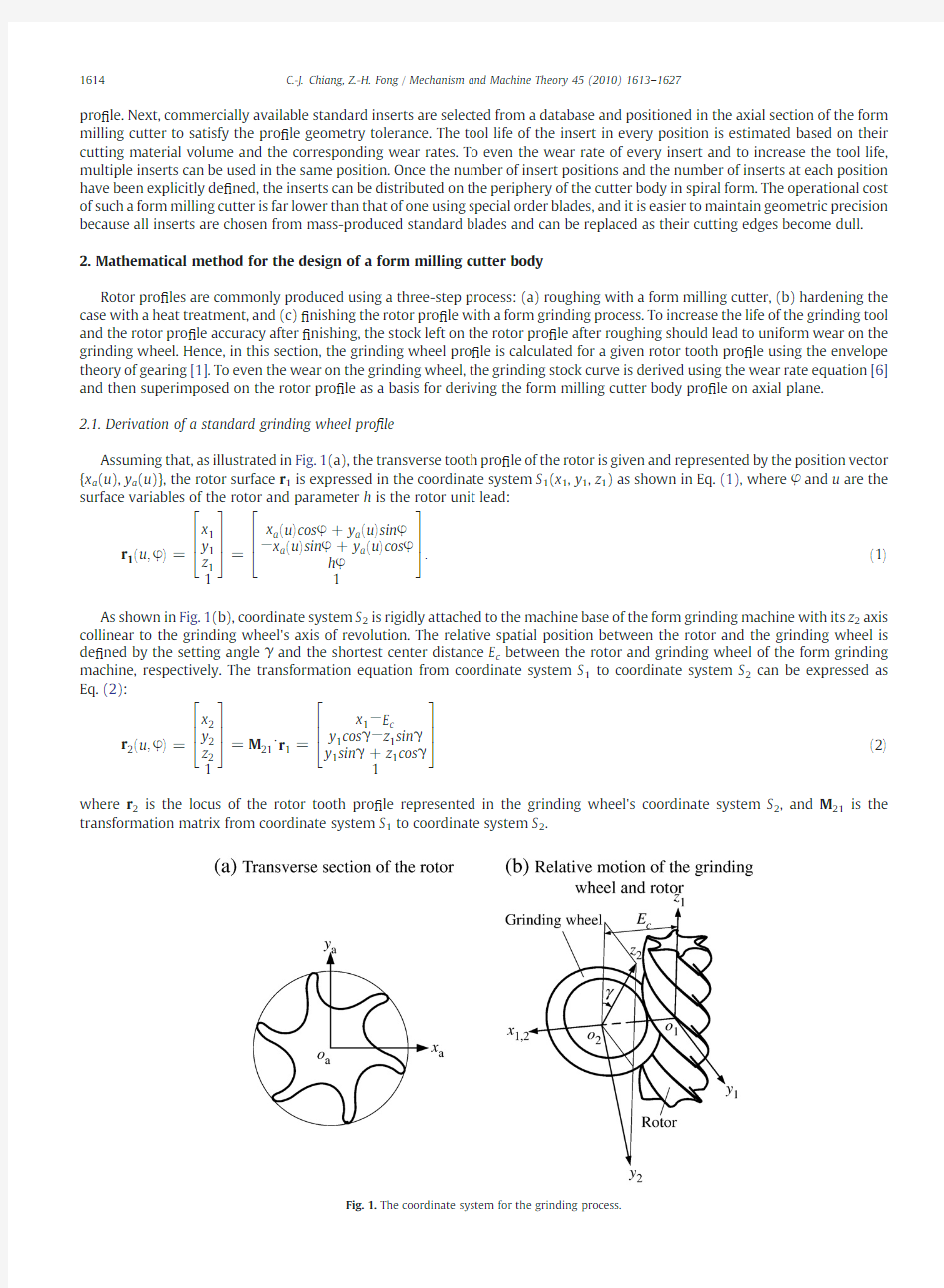
Assuming that,as illustrated in Fig.1(a),the transverse tooth pro ?le of the rotor is given and represented by the position vector {x a (u ),y a (u )},the rotor surface r 1is expressed in the coordinate system S 1(x 1,y 1,z 1)as shown in Eq.(1),where φand u are the surface variables of the rotor and parameter h is the rotor unit lead:
r 1eu ;φT=x 1y 1z 112
6643
7
75=x a eu Tcos φ+y a eu Tsin φ
?x a eu Tsin φ+y a eu Tcos φh φ
1
26643775:e1T
As shown in Fig.1(b),coordinate system S 2is rigidly attached to the machine base of the form grinding machine with its z 2axis
collinear to the grinding wheel's axis of revolution.The relative spatial position between the rotor and the grinding wheel is de ?ned by the setting angle γand the shortest center distance E c between the rotor and grinding wheel of the form grinding machine,respectively.The transformation equation from coordinate system S 1to coordinate system S 2can be expressed as Eq.(2):
r 2eu ;φT=x 2y 2z 2126643
7
75=M 21?r 1=x 1?E c
y 1cos γ?z 1sin γy 1sin γ+z 1cos γ126643775
e2Twhere r 2is the locus of the rotor tooth pro ?le represented in the grinding wheel's coordinate system S 2,and M 21is the
transformation matrix from coordinate system S 1to coordinate system S 2
.
Fig.1.The coordinate system for the grinding process.
1614 C.-J.Chiang,Z.-H.Fong /Mechanism and Machine Theory 45(2010)1613–1627
The unit normal of the grinding wheel surface can be expressed as in Eq.(3),after which the equation of meshing can be derived as Eq.(4)using the theory of gearing:
n 2eu ;φT=n x 2n y 2n z 21
2
6643775=?r 2=?u ×?r 2=?φj ?r 2=?u ×?r 2
=?φj
e3T
f u ;φeT=x 2n z 2?z 2n x 2?h +E c cot γeTn y 2?h cot γ?E c eTn z 2=0:
e4T
The grinding wheel pro ?le can then be obtained by substituting the surface variable φsolved from Eq.(4)into Eq.(2).
2.2.Mathematical method for obtaining the form cutter body pro ?le
The grinding wheel pro ?le can be represented by the position vector r 2(g )
(v 1)on the x 2z 2-plane,as shown in Eq.(5).
r eg T2ev 1T=x eg T
2ev 1Ty eg T2ev 1Tz eg T2ev 1T1
266666643
7
777775
=?????????????????x 22+y 2
2q 0z 2126666643
777775e5T
where v 1is the curve variable of the grinding wheel.
The grinding stock is the material that the grinding wheel removes from the workpiece.As shown in Fig.2,the grinding stock
on a rotor groove is a function of the grinding wheel pro ?le r 2(g )(v 1),the grinding stock curve r 2(s )
(v 1,a s ),and the workpiece length l wp .The volume dV s ,formed by the area of the grinding stock elements dA s and l wp ,is also a grinding stock element,where dv 1and the grinding stock depth of the workpiece a s are the area variables of dA s
.
Fig.2.Grinding stock for a rotor groove.
1615
C.-J.Chiang,Z.-H.Fong /Mechanism and Machine Theory 45(2010)1613–1627
The grinding stock curve r 2(s )
in coordinate system S 2can then be derived as Eq.(6)and,because the elemental areas on every rotor transverse plane are equal,the volume dV s of the grinding stock elements can be derived as Eq.(7):
r es T2ev 1;a s T=x es T
2
y es T2z es T21
2
666666437777775=x eg T
2?a s
y eg T2z eg T2
1
2
666666437777775
e6T
dV s =dA s l wp =a s dv 1l wp :
e7T
The wear on the grinding wheel occurs as it grinds the workpiece grinding stock during the manufacturing process.As shown
in Fig.3,the elemental wear volume is calculated from the grinding wheel pro ?le r 2(g )and the wear curve r 2(w )
.Additionally,
because the volume dV w is an element of wear,the wear area for dA w is the axial intersection of dV w ,where dv and the wear depth a w for the grinding wheel are the area variables of dA w .
The elemental wear volume dV w is derived as follows:
dV w =2πx eg T
2dA w =2πx eg T
2a w dv 1:
e8T
However,the wear rate κ,expressed below as Eq.(9)and de ?ned as the ratio of the grinding wheel wear volume to the material volume removed from the workpiece,greatly in ?uences grinding wheel wear and the surface quality of the rotors:
κ?V w V s
e9T
where V w is the grinding wheel wear volume and V s the material volume removed from the workpiece.To ensure equal wear for each grinding wheel element,the corresponding dV s and dV w must be calculated.Assuming that the grinding wheel has n segments,the condition that produces equal wear can be expressed as Eq.(10)and simpli ?ed as Eq.(11):
dV w ;1s ;1=dV w ;2s ;2=?=dV w ;n
s ;n e10T
a w ;1x eg T
2j v 1=v 1;1
s ;1
=
a w ;2x eg T
2j v 1=v 1;2
s ;2
=?=
a w ;n x eg T
2j v 1=v 1;n
s ;n
:e11T
When the grinding wheel has worn down,the grinding wheel diameter becomes smaller;therefore,to produce the correct
workpiece surface,the new grinding wheel pro ?le r 2
(g )′
must correspond to the new grinding wheel diameter (see Fig.4).In addition,the grinding wheel wear depth must equal the variation in the grinding wheel pro ?le given different manufacturing parameters and grinding wheel and workpiece materials.The elemental wear depth a w ,1can be obtained by experiment and the
new grinding wheel pro ?le r 2
(g )′
calculated by subtracting a w ,1from E c and applying Eqs.(1)to (5).The other elemental wear depths a w ,2~a w ,n can then be obtained using the variation in the grinding wheel pro ?le.
Once the grinding wheel wear depth and elemental grinding stock depth a s ,1have been calculated,the grinding stock curve r 2
(s )
can be obtained using Eq.(11).The grinding wheel pro ?le,grinding stock curve,and form milling cutter body pro ?le r 2(b )
are
given
Fig.3.Wear volume of the grinding wheel.
1616 C.-J.Chiang,Z.-H.Fong /Mechanism and Machine Theory 45(2010)1613–1627
in Fig.5,where a b is the depth between the grinding wheel pro ?le and form milling cutter body pro ?le.This same concept can be
used to derive the form milling cutter body pro ?le as expressed in Eq.(12).The area between r 2(s )and r 2(b )
can then be used to arrange the standard inserts.
r eb T
2
=x eb T
2
y eb T2z eb T21
2
66666643777
7775=x eg T
2?a b
y eg T2z eg T2
1
26666664
37777775
e12T
3.Mathematical method for distributing inserts on the form milling cutter body
This section outlines the de ?nition of the insert's cutting edge in the local coordinate system and its projection onto the form milling cutter body pro ?le on the axial plane.The geometric relations among the grinding stock,form milling cutter body pro ?le,and the insert can then be used to distribute the inserts on the form milling cutter
body.
Fig.4.Variation in the grinding wheel wear
depth.
Fig.5.Grinding wheel pro ?le,grinding stock curve,and form milling cutter body pro ?le.
1617
C.-J.Chiang,Z.-H.Fong /Mechanism and Machine Theory 45(2010)1613–1627
3.1.Mathematical method of inserts
As shown in Fig.6,the spatial relation between the insert and the form milling cutter body is de?ned by the following: inclinationσ,which rotates around the x5-axis;rotational angleζ,which rotates around the y4-axis;radial offset R bc;axial offset Z bc;and index angle?,which rotates around the z2-axis.Assuming that the insert's cutting edge is given and expressed in coordinate system S d(x d,y d,z d)as shown in Eq.(13),whereτis the curve variable,the matrix transformation from coordinate system S d to coordinate system S2can be expressed as Eq.(14):
r deτT=
x d
y d
z d
1
2
66
4
3
77
5;z d=0e13T
redT2=
xedT
2
yedT
2
zedT
2
1
2
66
66
66
66
4
3
77
77
77
77
5
=M23?M34?M45?M5d?r d
=
eR bc+x d cosζ+y d sinσsinζTcos??y d cosσsin?
y d cosσcos?+eR bc+x d cosζ+y d sinσsinζTsin?
Z bc?x d sinζ+y d sinσcosζ
1
2
66
64
3
77
75
e14T
where
M5d=
1000 0cosσ?sinσ0 0sinσcosσ0 0001 2
66
4
3
77
5
M45=
cosζ0sinζ0
0100
?sinζ0cosζ0
0001
2
66
4
3
77
5
Fig.6.Insert in the form milling cutter system.
1618 C.-J.Chiang,Z.-H.Fong/Mechanism and Machine Theory45(2010)1613–1627
M 34
=100R bc 0100001Z bc 00012
6643
7
75
M 23
=cos ??sin ?00sin ?cos ?0000
100001
2
6643
775:Based on Eq.(14)and the above parameters,the inserts can then be distributed on the form milling cutter body.3.2.Mathematical method for arranging inserts on the form milling cutter body pro ?le
This section explains the arrangement of inserts on the form milling cutter body pro ?le using the geometric relations among the grinding stock,the form milling cutter body pro ?le,and the insert's cutting edge.Based on Eq.(14),the cutting edges of the
inserts on the x 2z 2-plane can be derived as in Eq.(15)and drawn as in Fig.7.Here,j b is the number of the insert positions,P 2(s )
is a point of the grinding stock curve that is tangent to the insert's cutting edge,n 2(s )is the normal of the grinding stock curve,t 2(d )is the
tangent of the insert's cutting edge,and Q 2(b )
is a point on the form milling cutter body pro ?le that intersects with the insert's cutting edge:
r e?d
T2
=x e?d T2y e?d T2z e?d T21
2
6
6666666643
7777777775=M 2?3?M 34?M 45?M 5d ?r d
=?R bc ?x d cos ζ?y d sin σsin ζ
0Z bc ?x d sin ζ+y d
sin σcos ζ1
26
6
66437
7775
e15T
where
M 2?
3=?100000000
01000
01
2
6643775
:Fig.7.Arrangement of inserts on the form milling cutter body.
1619
C.-J.Chiang,Z.-H.Fong /Mechanism and Machine Theory 45(2010)1613–1627
This geometric arrangement method can be divided into the following basic steps: 1.Determining the inclinationσaccording to the cutting condition;
2.Selecting the end point of the grinding stock as P
2,j
b =1
(s);
3.Calculating the cutting edge r
2,j
b =1
(d)of the?rst insert using Eqs.(16)–(18);
4.Calculating point Q
2,j
b =1
(b),at which the form milling cutter body pro?le intersects with the insert's cutting edge;
5.Calculating the insert's cutting edge r
2,j
b =2
(d)based on the grinding stock curve,point Q
2,j
b =1
(b),and Eqs.(17)–(19);
6.Calculating point P
2,j
b =2
(s)at which the grinding stock curve intersects with the insert's cutting edge;and
7.Calculating the other inserts'cutting edges using the same process.
re?dT
2
?PesT2=0e16T
te?dT
2
?nesT2=0e17T
ζ=tan?1nesT
y2=nesT
x2
e18T
re?dT
2
?QebT2=0:e19T
The geometric arrangement method also allows calculation of the total number of insert cutting edges,which,once the index angles are provided,can then be distributed on the form milling cutter body using Eq.(14).
4.Variation in the tool life of every insert
Because the volume of material removed by each insert is different,each has a different tool life.Nonetheless,if the variation in tool life is known,it is easier to gauge when the cutting edge will become dull and the insert need replacing.Eq.(20)represents the insert tool life T of the turning tool described by Chu[10],which consists of the cutting speed v c,the feed rate f z,and the cutting depth a q,to which the cutting parameter C t is not relative.Eq.(21)expresses the equation of the cutting speed:
T=
C t
v1=m
c
f1=n
z
a1=Q
q
e20T
v c=R bcωce21Twhere1/m,1/n,and1/Q are the relative exponents of v c,f z,and a q,andωc is the angular velocity.The proportion of every insert's tool life can then be simpli?ed as Eq.(22),where symbolλis the times that an insert can be repeated based on its geometric shape:
T1:T2:???:T j=
λ1
R1=m
bc;1
a1=Q
q;1
:
λ2
R1=m
bc;2
a1=Q
q;2
:???:
λj
R1=m
bc;j
a1=Q
q;j
:e22T
The variation in the actual tool life of the form milling cutter inserts can be approximated using the insert numberξand the volume of material removed from the workpiece by insert V r.The proportion of every insert's tool life can then be derived as in Eq.(23).
T′1:T′2:???:T′j=
λ1ξ1
V r;1R1=m
bc;1
a1=Q
q;1
:
λ2ξ2
V r;2R1=m
bc;2
a1=Q
q;2
:???:
λjξj
V r;j R1=m
bc;j
a1=Q
q;j
e23T
To test the proposed mathematical method,a form milling cutter(see Fig.8)is designed in which intersection area A r,where the material removed from the workpiece intersects with the x2z2-plane,is formed by curve r2(ê)and the insert cutting edges.Here, D(g)represents the workpiece's outer diameter.The equation of the workpiece's outer circle surface is derived by Eq.(24),where symbol t andθare the surface variables.The transformation equation from coordinate system S1to coordinate system S2can then be expressed as Eq.(25),which can in turn be used with the equation of the x2z2-plane(Eq.(26))to derive the surface variable t of 1620 C.-J.Chiang,Z.-H.Fong/Mechanism and Machine Theory45(2010)1613–1627
curve r2(ê)(Eq.(27)).Subsequently,the workpiece's outer circle surface curve r2(ê)can be obtained using Eq.(28).
reeT1=
xeeT
1
yeeT
1
zeeT
1
1
2
66
66
66
4
3
77
77
77
5
=
eDegT=2Tcosθ
eDegT=2Tsinθ
t
1
2
66
4
3
77
5e24T
reeT2=
xeeT
2
yeeT
2
zeeT
2
1
2
66
66
66
4
3
77
77
77
5
=M21?reeT1=
xeeT
1
?E c
yeeT
1
cosγ?zeeT
1
sinγ
yeeT
1
sinγ+zeeT
1
cosγ
1
2
66
66
66
4
3
77
77
77
5
e25T
yeeT2=yeeT
1
cosγ?zeeT
1
sinγ=0e26
T
Fig.9.Transverse pro?le of the
rotors.
Fig.8.Material removed from the workpiece by the inserts.
1621
C.-J.Chiang,Z.-H.Fong/Mechanism and Machine Theory45(2010)1613–1627
t =
D eg T
=2 sin θcot γe27T
r e?e
T2
=x e?e
T2
y e?e T2z e?e T21
266666643
77777
75=eD eg T=2Tcos θ?E c
0eD eg T=2Tsin θesin γ+cot γcos γT1
26643775:e28T
The equations for V r and A r are derived as Eqs.(29)and (30),where τmin and τmax represent the range of the insert's cutting
edge and θmin and θmax designate the range of the surface curve of the workpiece's outer circle.The continued proportion of every insert's tool life can then be derived as Eq.(31).
V r =A r l wp e29T
A r =∫
z e?
d T2eτmax Tz e?d T2eτmin Tx e?d T2eτTdz e?d T2?∫z e?e
T2eθmax Tz e?e T2eθmin Tx e?e T2eθTz e?e T2=∫
τmin
τmax x e?d T2eτTdz e?d T2
d τ
d τ?∫
θmin θmax x e?e T
2
eθTdz e?e T2
d θ
d θ
e30T
Table 1
Basic data for the rotor and machine setups in the example.Parameters
Female Male Shortest center distance E c (mm)162.25181.95Setting angle γ(deg)4444Unit lead h (mm/rad)
68.47
57.06
Fig.10.Grinding wheel,grinding stock,and form milling cutter body pro ?les;relative curves of the workpiece's grinding stock depth;and length between the grinding wheel and form milling cutter body pro ?les.
1622 C.-J.Chiang,Z.-H.Fong /Mechanism and Machine Theory 45(2010)1613–1627
T ′1:T ′2:???:T ′k =
λ1ξ1A r ;1R 1=m bc ;1a 1=Q
q ;1
:
λ2ξ2A r ;2R 1=m bc ;2a 1=Q
q ;2
:???:
λj ξj
A r ;j R 1=m bc ;j a 1=Q
q ;j
:e31T
Once the manufacturing parameters are obtained,Eq.(31)can be used to calculate the insert replacement time (i.e.,the time it
will take for an insert's cutting edge to become dull).5.Numerical example and discussion
Because of its worldwide use,the SANDVIK standard insert [8]was selected for arrangement on the form milling cutter axial section.The transverse pro ?les of the rotors for an air compressor are shown in Fig.9,and the basic rotor parameter and machine setups are given in Table 1.The pro ?les of the grinding wheel,grinding stock,and form milling cutter body calculated using Eqs.(1)–(12)are given in Fig.10(a)and (b),while the relative curves of the workpiece's grinding stock depth and the length between the grinding wheel and form milling cutter body pro ?les are shown in Fig.10(c)and (d).
For this example,round and rhombic inserts were selected from the SANDVIK brochure (see Fig.11),and their explicit cutting edge equations derived as in Table 2.The corresponding segment parameters for the insert cutting edges are as listed in Table 3.The form milling cutters could then be designed using the proposed geometrical arrangement method (see Fig.12)and the inserts
Table
2
Explicit equations for the segments of the round and rhombic insert cutting edges.Round insert Segment Explicit equation
Range All
x d eτT=iCcos τy d eτT=iCsin τ
0≤τ≤2π
Rhombic insert Point Position vector
c 1{c 1x
d ,c 1y d }={l cos(δ/2)?r ε/sin(δ/2),0}A d {A x d ,A y d }={c 1x d +r εsin(δ/2),?r εsin(δ/2)}B d {B x d ,B y d }={c 1x d +r εsin(δ/2),r εsin(δ/2)}C d {C x d ,C y d }={0,l sin(δ/2)}
D d {D x d ,D y d }={?c 1x d ?r εsin(δ/2),r εsin(δ/2)}
E d {E x d ,E y d }={?c 1x d ?r εsin(δ/2),r εsin(δ/2)}
F d
{F x d ,F y d }={0,?l sin(δ/2)}
Segment Explicit equations Range A d –B d x d eτT=c 1x d +r εcos τy d eτT=c 1x d +r εsin τ
?
π2+δ2≤τ≤π2?δ2
B d –
C d x d eτT=lcos eδ=2T?lcos eδ=2Tτy d
eτT=lsin eδ=2Tτ
lcos eδ=2T?B x d
lcos eδ=2T≤τ≤1
C d –
D d x d eτT=?lcos eδ=2T+lcos eδ=2Tτy d
eτT=lsin eδ=2Tτ lcos eδ=2T?B x d
lcos eδ=2T≤τ≤1
D d –
E d x d eτT=?c 1x d ?r εcos τy d eτT=c 1x d +r εsin τ ?π2+δ2≤τ≤π2?δ2E d –
F d x d eτT=?lcos eδ=2T+lcos eδ=2Tτy d eτT=?lsin eδ=2Tτ
lcos eδ=2T?B x d
lcos eδ=2T≤τ≤1
F d –A d
x d eτT=lcos eδ=2T?lcos eδ=2Tτy d eτT=?lsin eδ=2Tτ
lcos eδ=2T?B x d
lcos eδ=2T
≤τ≤1
Fig.11.Cutting edges of the round and rhombic inserts.
1623
C.-J.Chiang,Z.-H.Fong /Mechanism and Machine Theory 45(2010)1613–1627
arranged according to the distribution parameters given in Table 4.The workpiece and form milling cutter materials selected to obtain the relative exponents were steel 3Cr12Ni8Mn8MoV and alloy YT15[6].The tool life variations for all the inserts were derived as shown in Fig.13based on the data listed in Table 5.6.Conclusion
The results of the numerical example suggest the following conclusions:
1.The grinding stock allowance curve that produces equal wear on the grinding wheel can be derived using the wear rate equation.
https://www.doczj.com/doc/2a12483450.html,mercially available standard inserts can be positioned in the axial section of the form milling cutter to satisfy pro ?le geometry
tolerance.
Fig.12.Arrangement of inserts on the form milling cutter axial section.
Table 3
Segment parameters of the round and rhombic insert cutting edges.Round insert
Circle diameter iC (mm)12mm
Rhombic insert
Include angle δ(deg)
55Cutting edge length l (mm)11Nose radius r ?(mm)
1.2
1624 C.-J.Chiang,Z.-H.Fong /Mechanism and Machine Theory 45(2010)1613–1627
3.The tool life of the insert in every insert position can be estimated based on its cutting material volume and the corresponding wear rates.
4.Such a form milling cutter has a far lower operational cost than those that use special order blades,and its use of easily replaceable mass-produced standard blades makes it easier to maintain geometric precision.
5.The proposed mathematical method can also be used to design a form milling cutter with other types of standard inserts.In sum,because the proposed mathematical method can be used to design form milling cutters with multiple standard inserts for rotor manufacture,it is not only a good compromise in terms of grinding wear and manufacturing cost but suitable for manufacturing other cylindrical
gears.
Fig.13.Variations in tool life for all inserts.
Table 4
Distribution parameters for the inserts on the form milling cutters.Insert
σ(deg)
ζ(deg)R bc (mm)Z bc (mm)?(deg)Inserts on the form milling cutter:female rotor 1623.0292.8633.76?14.27268.4496.9332.9?56.95369.00103.7531.90?98.454720.27109.4525.00?140.845729.24112.7523.49?184.456745.54116.1021.01?228.127788.90118.0817.16?272.3787117.66116.6912.14?4.3597134.76113.778.22?51.07107145.42110.30 5.36?98.22116154.84106.04?3.07?146.06126151.5097.37?7.22?197.57136141.13
90.94
?11.24
?248.16
Inserts on the form milling cutter:male rotor 1671.26
90.9119.76?208.992656.5593.5714.43?168.063646.0197.629.45?126.734638.73102.69 4.86?85.215634.02108.580.56?43.62675110.92?5.62?3.04775114.98?8.22?322.07878115.77?9.13?281.899714115.59?9.40?241.9310710114.17?10.03?202.26116156.79111.88?15.12?162.80126151.95106.31?17.80?124.22136147.60100.51?21.18?85.85146143.6894.67?25.19?47.69156
122.6791.35?28.35?8.83
1625
C.-J.Chiang,Z.-H.Fong /Mechanism and Machine Theory 45(2010)1613–1627
1626 C.-J.Chiang,Z.-H.Fong/Mechanism and Machine Theory45(2010)1613–1627
Table5
Data for calculating the tool life variations for all inserts.
Relative exponents
1/m5
1/Q0.75 InsertξλA r(mm2)a q(mm)
Form milling cutter:female rotor
12120.94 1.10 225 5.420.94 32229.35 2.00 42931.96 1.54 52767.15 2.67 625152.68 5.09 744278.858.38 826200.06 6.24 925125.59 4.39 102474.12 3.02 112690.06 5.12 122332.65 4.08 1322 6.17 3.49
Form milling cutter:male rotor
126 4.25 5.30 22518.63 5.09 32537.12 4.73 42557.13 4.39 52480.38 4.23 62279.64 4.77 742112.67 5.77 82258.88 1.76 94256.03 2.73 102241.13 2.29 112648.74 2.25 122548.14 3.00 132536.92 3.66 142516.42 3.80 15211 1.58 2.79
Nomenclature
u surface variable of the rotor
φsurface variable of the rotor
h unit lead of the rotor
γsetting angle
E c shortest center distance between the workpiece and the grinding wheel
l wp workpiece length
dV s elemental volume of the grinding stock
dA s elemental area of the grinding stock
a s grinding stock depth of the workpiece
dV w elemental volume of wear
dA w elemental area of wear
a w area variable of dA w
κratio of the grinding wheel wear volume to the volume of material removed from the workpiece
V w wear volume of the grinding wheel
V s volume of material removed from the workpiece
v1curve variable of the grinding wheel pro?le
a b depth between the grinding wheel pro?le and the form milling cutter body pro?le
σinclination of the insert
ζrotational angle of the insert
R bc radial offset of the insert
Z bc axial offset of the insert
?index angle of the insert
τcurve variable of the insert cutting edge
τmin,τmax range of the insert cutting edge's curve variable
j b insert position number
T insert tool life v c cutting speed f z feed rate a q cutting depth C t cutting parameter not relative to v c ,f z ,and a q 1/m relative exponent of v c 1/n relative exponent of f z 1/Q relative exponent of a q ωc angular velocity λtimes that an insert can be repeated based on its geometric shape ξinsert number V r volume of material the insert removes from the workpiece A r intersection area of the material removed from the workpiece and the x 2z 2-plane D (g )outer diameter of the workpiece t surface variable of the workpiece's outer circle surface θsurface variable of the workpiece's outer circle surface θmin ,θmax range of the surface variable θ
Subscripts 1rotor 2grinding wheel s stock w wear
References
[1] F.L.Litvin,Theory of Gearing,1212,NASA Reference Publication,Washington,DC,1989.
[2] F.L.Litvin,A.Fuentes,Gear Geometry and Applied Theory,2nd.ed.Cambridge University Press,New York,2004.[3]Z.W.Xing,Screw Compressor:Theory Design and Application,China Machine Press,2000.
[4]H.Y.You,P.Q.Ye,J.S.Wang,X.Y.Deng,Design and application of CBN shape grinding wheel for gears,International Journal of Machine Tools and Manufacture 44(2003)1269–1277.
[5]N.Stosic,A geometric approach to calculating tool wear in screw rotor machining,International Journal of Machine Tools and Manufacture 46(2006)1961–1965.
[6] D.Q.Wang,Y.Chen,Properties of Grinding Wheels and the Grinding Manufacture,Standards Press,China,2001.[7]FETTE,Hobs,Gear Cutter [brochure],Germany.
[8]SANDVIK Coromant,Turning Tools [brochure],Sweden,2006.
[9]S.Engin,Y.Altintas,Mechanics and dynamics of general milling cutters.II.Inserted cutters,International Journal of Machine Tools and Manufacture 41(2001)2213–2231.
[10]H.Chu,Practical Cutter Technology of Metal Cutting,China Machine Press,2002.
[11] A.Richetti,A.R.Machado,M.B.Da Silva,E.O.Ezugwu,J.Bonney,In ?uence of the number of inserts for tool life evaluation in face milling of steels,International Journal of Machine Tools &Manufacture 44(7–8)(2004)695–700.
[12] A.M.de Souza Jr.,W.F.Sales,S.C.Santos,A.R.Machado,Performance of single Si 3N 4and mixed Si 3N 4+PCBN wiper cutting tools applied to high speed face milling of cast iron,International Journal of Machine Tools &Manufacture 45(3)(2005)335–344.
[13]P.K.Baro,S.S.Joshi,S.G.Kapoor,Modeling of cutting forces in a face-milling operation with self-propelled round insert milling cutter,International Journal of Machine Tools and Manufacture 45(7–8)(2005)831–839.
[14]
J.Gu,G.Barber,S.Tung,R.J.Gu,Tool life and wear mechanism of uncoated and coated milling inserts,Wear 225(1)(1999)273–284.
1627
C.-J.Chiang,Z.-H.Fong /Mechanism and Machine Theory 45(2010)1613–1627