JUPITER 2501 AOI
程
序
制
作
及
调
试
参
考
JUPITER 2501 AOI程序制作及调试参考
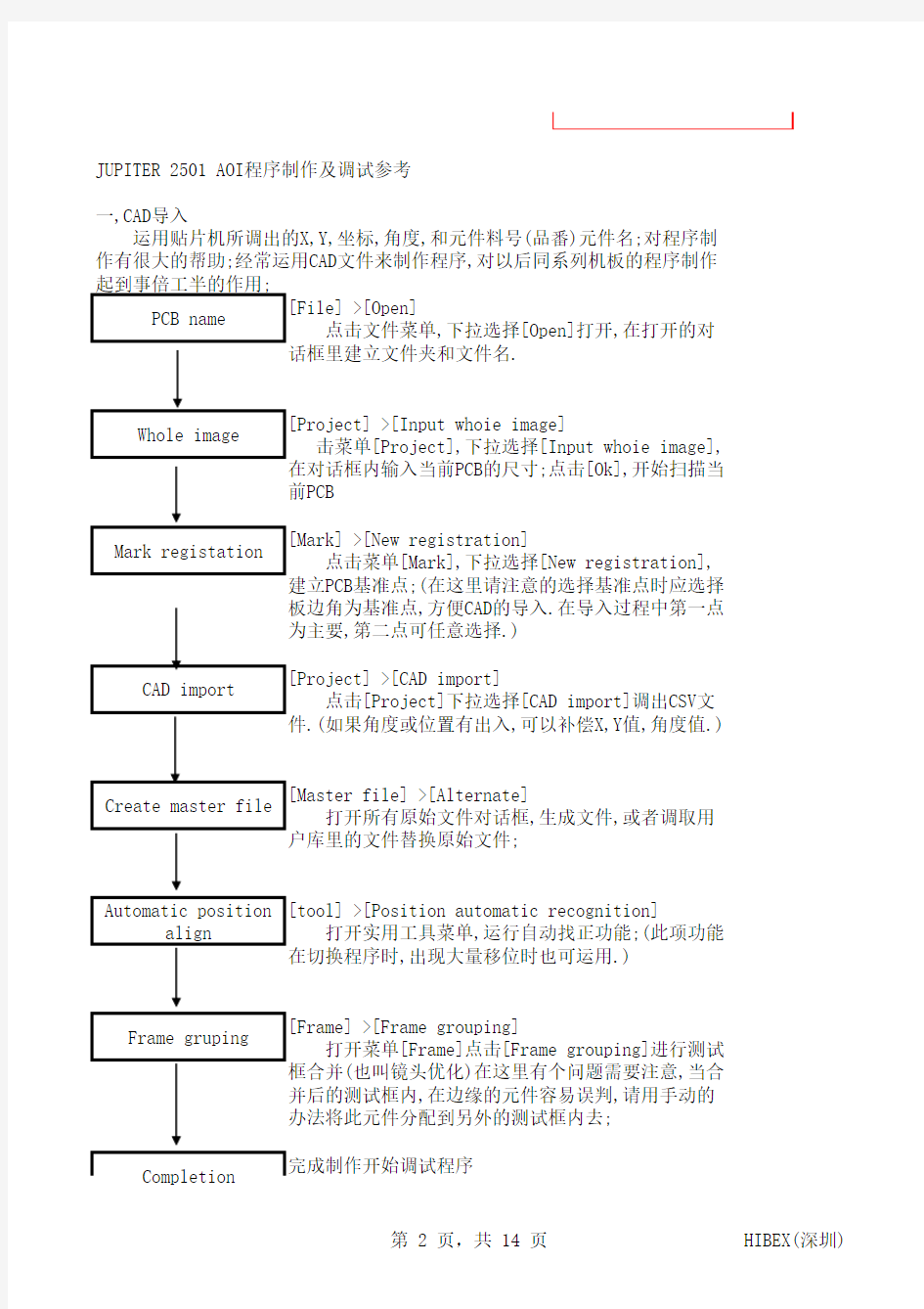
一,CAD导入[File] >[Open][Project] >[Input whoie image] [Mark] >[New registration][Project] >[CAD import][Master file] >[Alternate][tool] >[Position automatic recognition]
[Frame] >[Frame grouping]
完成制作开始调试程序
Frame gruping Completion 点击文件菜单,下拉选择[Open]打开,在打开的对
话框里建立文件夹和文件名.
击菜单[Project],下拉选择[Input whoie image],
在对话框内输入当前PCB的尺寸;点击[Ok],开始扫描当
前PCB
点击菜单[Mark],下拉选择[New registration],
建立PCB基准点;(在这里请注意的选择基准点时应选择
板边角为基准点,方便CAD的导入.在导入过程中第一点
为主要,第二点可任意选择.)
点击[Project]下拉选择[CAD import]调出CSV文
件.(如果角度或位置有出入,可以补偿X,Y值,角度值.)
运用贴片机所调出的X,Y,坐标,角度,和元件料号(品番)元件名;对程序制作有很大的帮助;经常运用CAD文件来制作程序,对以后同系列机板的程序制作起到事倍工半的作用;
打开所有原始文件对话框,生成文件,或者调取用
户库里的文件替换原始文件;
打开实用工具菜单,运行自动找正功能;(此项功能
在切换程序时,出现大量移位时也可运用.)
打开菜单[Frame]点击[Frame grouping]进行测试
框合并(也叫镜头优化)在这里有个问题需要注意,当合
并后的测试框内,在边缘的元件容易误判,请用手动的
办法将此元件分配到另外的测试框内去;
PCB name Whole image Mark registation CAD import Create master file Automatic position align
二,手工制作程序[File] >[Open][Project] >[Input whoie image] [Mark] >[New registration][Project] >[Patrts extraction][Master file] >[Alternate][tool] >[Position automatic recognition][Frame] >[Frame grouping]完成制作开始调试程序
打开所有原始文件对话框,生成文件,或者调取用
户库里的文件替换原始文件;在测试窗口制作程序时可
以变制作边调试,在编辑窗口内就不可做调试;
Create master file Automatic position align 打开实用工具菜单,运行自动找正功能;(此项功能
在切换程序时,出现大量移位时也可运用.)
Frame gruping 打开菜单[Frame]点击[Frame grouping]进行测试
框合并(也叫镜头优化)在这里有个问题需要注意,当合
并后的测试框内,在边缘的元件容易误判,请用手动的
办法将此元件分配到另外的测试框内去;
Completion
在这里先说明一下,当所制作机板相对比较简单(元件种类比较少,或者是多联板)时,可以运用手工制作程序.
PCB name 点击文件菜单,下拉选择[Open]打开,在打开的对
话框里建立文件夹和文件名.
Whole image 点击菜单[Project],下拉选择[Input whoie
image],在对话框内输入当前PCB的尺寸;点击[Ok],开
始扫描当前PCB
Part extraction 可以根据所做机板情况,选择在测试对话框内生成
原始文件,或者选择在编辑[Edit]窗口内生成原始文件
Mark registation 点击菜单[Mark],下拉选择[New registration],建
立PCB基准点;(在这里请注意选择基准点时应选择 PCB
上原有的基准点,并且是对角的,变化比较小的点;)
Completion
Troubleshooting for false reject
误判的调整和修改
A)Fillet error焊点错误
一,)If Pattren Matching is used 如果模型匹配有误差
1>Add Fillet Pattren (do not add NG image)
增加该有误差的模型,这里请注意不要增加错误的模型,请确保你所增加的
模型不要歪斜;因为有些误判是模型歪斜导致的!
2>Increase RGB Level value
Make sure insufficient Solder & Nosolder can be detected when
you use this value增加RGB的数值,在区分焊锡不足和没焊锡时对此数值也
3>Increase Pixel Judge value 增加像素判定值
4>Increase Fillet Search Area 增加搜寻范围
B) Position error 位置错误
1>Add Image Pattren (do not add NG image) 增加模型图片
2>Increase Position Determination value if component has various patterns 增加位置判定值,增加搜索范围
3>Increase RGB Level value if component has various patterms 在元
件有不同批次时增加RGB数值
C) Match error 元件模型错误
1>Add Image Pattern (do not add NG image) 增加模型图片
2>Adjust Mask Size 减少测试范围
3>Increase RGB Level value if component has various patterms 在元
件有不同批次时增加RGB数值
4>Increase Pixel Judge value 增加像素判定值
5>Increase Search Area if characters locate in various places,e.g.E-cap
(make sure component shifted can be detected when you use this value)
如果元件印刷有偏差,或者装贴位置偏移可以增加测试搜寻范围(但必需确认
真正的NG能测试得到)
D) Bridge error短路错误
1>Set Vertical White Light to 0 for Horizontal IC Leads IC 脚方
向为水平时请选择垂直方向的白光源
2>Set Horizontal White Light to 0 for Vertical IC Leade IC 脚方
向为垂直时请选择水平方向的白光源
3>Increase Determination Width value 增加短路测定值
4>Increase Binary value 增加二进制测定值
(make sure IC Bridge can be detected when you use this value) 要确
保IC 短路可以测试
5>Decrease Hue Level value
(make sure IC Bridge can be detected when you use this value)要确保
IC 短路可以测试
6>Use Lower LED,then adjust Binary value 用红色光源,适当调整二进制数值
7)Adjust Bridge Inspection Window Size 调整IC脚宽度
Jupiter 2501 AOI Machine Training Notes
1,Machine Hardware 机器硬件
1>PC 电脑硬件配置
> 1GB RAM 1GB 以上内存
> OS Wingdows 2000 Professional 操作系统Wingdows 2000专业版
> CD-RW CD刻录光驱
> Floppy Disk Deive 软驱
> Harddisk 160GB++ 160GB以上硬盘
> X,Y Control PCB(Stepping Motor Control Card) X-Y电机驱动卡
> IEEE 1394 PCB (Vision Control Card)1394 接口卡
> Hard Key (Software Protection) 键盘
2>Monitor 显示器
> 1280 X 1024 pixels 1280X1024 像素
3>Machine Main Body 机器主要硬件
> Front Cover 前置安全挡板
> PCB Loading Table 机板放置装置
> Emergency Button 紧急按钮
> Run Button 运行按钮
> Eject Button 机板取出按钮
> Power Switch 电源开关
> Cooling Fan 散热风扇
> Motor Control Cable 电机驱动数据线
> Vision Control Cable 图象数据线
> Power cable 电源线
> Full Digital XGA camera 照相机
> Red LED Lighting 红色LED光源
> White LED Lighting 白色LED光源
2,Software 软件
> Jupiter 2501 Machine Software
> Sonic Record Now (CDR Software)
3,Dimension of Board 测试机板尺寸
> Max Size:405mm X 265mm 最大尺寸405mm X 265mm
2501L: 500mm X 390mm
> Thickness: 0.5mm-2.0mm 机板厚度:0.5mm-2.0mm
> Part Height:Less than 40mm 机板高度:40mm(拆除红色LED光源可达45mm) > Height Clearance Under PCB: Less than 70mm 机板下端高度少于70mm
> Side Clearance: 3.0mm 元件伸出机板侧面最大可测3.0mm
4,Inspection Parts Chip 0402- 检测元件0402以上
5,Inspection ltems
> Missing part,wrong part ,polarity,upside
down,manhattan,bridge(lead pitch=0.3mm),missing solder,part
6,Inspection Method 检测方法
> Judgement:Pattern Matching 图象对比
> Position search:pin point search 位置检测
> OCR 文字抽出检测
> Hue 颜色检测
7,Resolution 分辨率
> Frame size:20mm X 15mm (28mm X 21mm) 测试镜头尺寸
> 40um/pixel(512 X 384 pixels) & 20um/pixel(1024 X 768 pixels)
8,Lighting System 照明系统
> Upper light-White(around 80 degree) 上段白光源(接近80度)
Combination by a number of white LED 由许多排列的白色LED组成
Divided to horizontal & vertical zone 划分成垂直和水平的两个光源区 Illumination of lighting can be set to 0%(off) 50% & 100%(fully) separately(useful for minimize bad influence from flux)光源可以设置为0%(关闭)50%(开启一半)100%(全部开启)(其设置根据助焊济溶解影响而定) > Lower light-Red(aroun45degree) 下段光源(接近45度)
Ring type 光圈样式
Combination by a number of red LED 由许多排列红色LED组成
Lighting can be set to on or off 可以设置为开启或关闭
(special for solder fillet check) 特别为检查焊接情况设定
9,Inspection Method 检测方法
Pattern Matching 模型检查
Check marking(i.e.IC polarity),printing
(i.e.numerial,alphabet),patten(i.e.connector shape)
极性检测(例如 IC.电容,二极管等极性元件)文字丝印( IC,电阻型号等)形状(元件破损等)
Bridge Check 短路检查
Solder bridging between leads of IC,connector,resistor
array,transistor and etc… 短路,连锡不良主要存在于IC,连接器,排阻,排容等脚上
Solder Fillet check 焊接情况检查
Can't stand alone;It mast together with pattern matching (default type) or bridge check 焊接状况检测必须和元件本体,或短路(IC脚)一起
OCR 文字抽出
一般运用于IC等元件的字体检查上
Hue 颜色检测
运用于大焊盘上的焊锡检测
10, Auto masking function
Auto-mask the IC leads,chip capacitor & resistor,it can be manually edited or modified also 贴片电容,电阻,IC等的本体模型也
可以通过手工编辑来修改或修正;
11, Library 图库
At initial stage,library is empty,data will be collected, fill
& accumulate during programming. 初次的图库里是空的,图库里的数据是
同过不断的从新程序里采集得到,在不断的更新和管理中得到数据
The data can be added, deleted,edited time to time
数据可以增加,删除,编辑
> CAD Library CAD 图库
It works when using CAD data(SMT mount data) input
制作新程序工厂应当使用CAD数据(SMT数据)
Size of library is depending on PC's memory limitation
CAD库的存储量根据电脑硬盘配置来决定
Data registration including image,component part name,mounting angle,component size & individual parameter setting
数据记录包括了元件图象,名称,料号(品番),角度,元件尺寸,以及各测试参数 The data will be scanned,recognized & copied out automatically when CAD data imported for programming.(Auto-extraction)
制作新程序输入数据时将会被扫描和识别,自动调出相同料号的数据
The CAD must in CSV file format & must include Location(less
than 10 characters),name(less than 10 characters),Part name(less
than 25 characters),A side(P)/B side(S), X coordinate(-375.00~
+375.00)mm,Y coordinate(-265.00~+265.00)mm,Angle(0,90,180,270 degree) 6 items in proper sequence
CAD 数据必须转换成CSV文件格式,一定要包含元件名,元件料号(品番)A
面要(P)表示,B面要(S)表示.X轴坐标(-375.00~+375.00)mm,Y轴坐标(-
265.00~+265.00)mm,角度(0,90,180,270 度)依次排列的6个项目
CAD 数据必须转换成CSV文件格式,一定要包含元件名,元件料号(品番)A
面要(P)表示,B面要(S)表示.X轴坐标(-375.00~+375.00)mm,Y轴坐标(-
265.00~+265.00)mm,角度(0,90,180,270 度)依次排列的6个项目
> User Library 用户图库
It works when manual or auto teaching programming
当手工制作时是元件本体已经调整好参数的参考图库
Size of library is limited to 1152 master file
图库里可以储存多达1152个元件文件
Each master file save up to 50 patterns,fillet images are not included 每个元件都有50个标准模型,焊点不包括在内
Data registration include image,component size & individual parameter setting only
数据记录包含元件图象,尺寸大小,和一定的参数设定
The data can extract out any time for different model programming
此数据参数可以生成其他的新模型
12,AOI Program Method AOI 程序制作方法
They are two main Method 主要是两种方法
Auto Teaching Programming -Create AOI program without customer
SMT Mounter CAD Data
手工制作法
CAD Import Programming - Create AOI program with customer SMT Mounter CAD Data
CAD 导入法--
Ic lead(Using Pattern matching for solder fillet inspection) IC 焊接情况检查
IC Lead (Using Form Inspection for solder fillet inspection)
Al Lead Pins
1608 Chip