附录
How Manual Transmissions Work
If you drive a stick-shift car, then you may have several questions floating in your head.
How does the funny "H" pattern that I am moving this shift knob through have any relation to the gears inside the transmission? What is moving inside the transmission when I move the shifter?
When I mess up and hear that horrible grinding sound, what is actually grinding? What would happen if I were to accidentally shift into reverse while I am speeding down the freeway? Would the entire transmission explode?
In this article, we'll answer all of these questions and more as we explore the interior of a manual transmission.
Cars need transmissions because of the physics of the gasoline engine. First, any engine has a redline --a maximum rpm value above which the engine cannot go without exploding. Second, if you have read How Horsepower Works, then you know that engines have narrow rpm ranges where horsepower and torque are at their maximum. For example, an engine might produce its maximum horsepower at 5,500 rpm. The transmission allows the gear ratio between the engine and the drive wheels to change as the car speeds up and slows down. You shift gears so the engine can stay below the redline and near the rpm band of its best performance.
Ideally, the transmission would be so flexible in its ratios that the engine could always run at its single, best-performance rpm value. That is the idea behind the continuously variable transmission (CVT).
A CVT has a nearly infinite range of gear ratios. In the past, CVTs could not compete with four-speed and five-speed transmissions in terms of cost, size and reliability, so you didn't see them in production automobiles. These days, improvements in design have made CVTs more common. The Toyota Prius is a hybrid car that uses a CVT.
The transmission is connected to the engine through the clutch. The input shaft of the transmission therefore turns at the same rpm as the engine.
A five-speed transmission applies one of five different gear ratios to the input shaft to
produce a different rpm value at the output shaft.
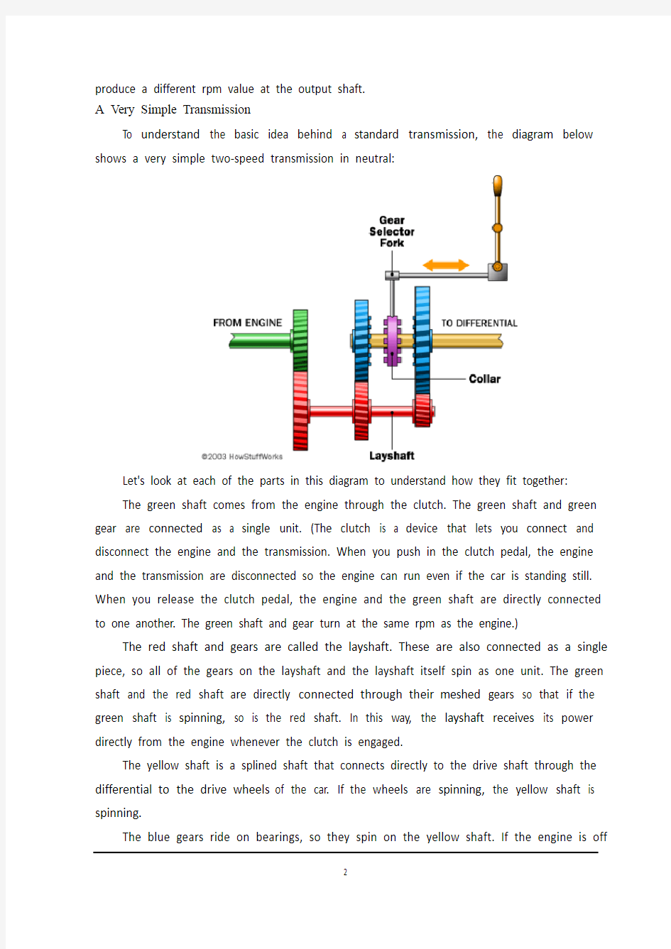
A Very Simple Transmission
To understand the basic idea behind a standard transmission, the diagram below shows a very simple two-speed transmission in neutral:
Let's look at each of the parts in this diagram to understand how they fit together:
The green shaft comes from the engine through the clutch. The green shaft and green gear are connected as a single unit. (The clutch is a device that lets you connect and disconnect the engine and the transmission. When you push in the clutch pedal, the engine and the transmission are disconnected so the engine can run even if the car is standing still. When you release the clutch pedal, the engine and the green shaft are directly connected to one another. The green shaft and gear turn at the same rpm as the engine.) The red shaft and gears are called the layshaft. These are also connected as a single piece, so all of the gears on the layshaft and the layshaft itself spin as one unit. The green shaft and the red shaft are directly connected through their meshed gears so that if the green shaft is spinning, so is the red shaft. In this way, the layshaft receives its power directly from the engine whenever the clutch is engaged.
The yellow shaft is a splined shaft that connects directly to the drive shaft through the differential to the drive wheels of the car. If the wheels are spinning, the yellow shaft is spinning.
The blue gears ride on bearings, so they spin on the yellow shaft. If the engine is off
but the car is coasting, the yellow shaft can turn inside the blue gears while the blue gears and the layshaft are motionless.
Now, let's see what happens when you shift into first gear.
First Gear
In this picture, the green shaft from the engine turns the layshaft, which turns the blue gear on the right. This gear transmits its energy through the collar to drive the yellow drive shaft. Meanwhile, the blue gear on the left is turning, but it is freewheeling on its bearing so it has no effect on the yellow shaft.
When the collar is between the two gears (as shown in the first figure), the transmission is in neutral. Both of the blue gears freewheel on the yellow shaft at the different rates controlled by their ratios to the layshaft.
From this discussion, you can answer several questions:
When you make a mistake while shifting and hear a horrible grinding sound, you are not hearing the sound of gear teeth mis-meshing. As you can see in these diagrams, all gear teeth are all fully meshed at all times. The grinding is the sound of the dog teeth trying unsuccessfully to engage the holes in the side of a blue gear.
The transmission shown here does not have "synchros" (discussed later in the article), so if you were using this transmission you would have to double-clutch it. Double-clutching was common in older cars and is still common in some modern race cars. In double-clutching, you first push the clutch pedal in once to disengage the engine from the transmission. This takes the pressure off the dog teeth so you can move the collar into neutral. Then you release the clutch pedal and rev the engine to the "right speed." The right speed is the rpm value at which the engine should be running in the next gear. The idea is to get the blue gear of the next gear and the collar rotating at the same speed so that the dog teeth can engage. Then you push the clutch pedal in again and lock the collar into the new gear. At every gear change you have to press and release the clutch twice, hence the name "double-clutching."
You can also see how a small linear motion in the gear shift knob allows you to change gears. The gear shift knob moves a rod connected to the fork. The fork slides the collar on the yellow shaft to engage one of two gears.
In the next section, we'll take a look at a real transmission.
A Real Transmission
There are three forks controlled by three rods that are engaged by the shift lever. Looking at the shift rods from the top, they look like this in reverse, first and second gear: Keep in mind that the shift lever has a rotation point in the middle. When you push the knob forward to engage first gear, you are actually pulling the rod and fork for first gear back.
You can see that as you move the shifter left and right you are engaging different forks (and therefore different collars). Moving the knob forward and backward moves the collar to engage one of the gears。
Reverse gear is handled by a small idler gear (purple). At all times, the blue reverse gear in this diagram is turning in a direction opposite to all of the other blue gears. Therefore, it would be impossible to throw the transmission into reverse while the car is moving forward -- the dog teeth would never engage. However, they will make a lot of noise!
手动变速器如何工作
如果你驾驶一台手动小轿车,那么你可能会有几个问题漂浮在脑海中。
当移动换挡操纵杆时,是怎样通过变速器中齿轮的联系实现有趣的“H”模式?当我移动操纵杆时,变速器里面是如何工作的呢?
当我换错挡并听到可怕的摩擦声时,实际是什么在磨削呢?如果我在高速公路上急行时,突然换倒档会发生什么情况呢?变速器会爆炸吗?
在本篇文章中,我们将回答所有这些问题,更要探索手动变速器内部。
由于物理学的汽油发动机,故汽车需要传输动力。首先,任何发动机都有一条红界限——转速超过最大值时,发动机不会运行也不会爆炸。第二,如果你知道马力是如何工作的,那么你一定知道当马力和扭矩达到最大值时,发动机的转速范围缩小。例如,发动机可能产生的最大马力为5500转。变速器使发动机和驱动车轮之间的传动比变小,以使汽车加速行驶。你变速行驶时,发动机能停留在红界限或界限附近以达到最佳行驶状态。
最理想的是,变速器以非常灵活的比率使发动机可以始终运行在单一的、最高性能的转速。这种想法基于连续的变速传动(无级变速器)。
无级变速器有近无穷的传动比范围。在过去,无级变速器在成本、大小和可靠性上不能与四档和五档变速器相比,所以没有大量运用于汽车生产中。近年来,无级变速器的改进设计更为常见。丰田普锐斯是一辆使用无级变速器的混合动力型汽车。
变速器通过离合器与发动机相连。因此,变速器输入轴与发动机以同样的转速转动。
五档变速器适用于五个不同的传动比的汽车,它把输入轴产生的不同转速值传给输出轴。
一个非常简单的变速器
为了理解一台标准变速器的原理,下面的图表显示了一个非常简单的中间轴式双速传动变速器:
让我们看一看图表中的每一部分,理解他们是怎样结合在一起的:发动机的动力通过离合器传给输入轴。输入轴和输入齿轮以一个单个单元连接。(离合器是一种装置,它可以连接和断开发动机和变速器。当你踏下离合器踏板时,发动机和离合器不连接,所以即使汽车停着不动,发动机也能运行。当你释放离合器踏板时,发动机与输入轴直接相连。输入轴与输出轴的转速与发动机相同。)
红色轴和齿轮被称为中间轴。这也是作为一个单一的连接件,所以所有的中间轴齿轮和其本身自旋为一个单元。输入轴和中间轴通过啮合齿轮直接相连,因此如果输入轴旋转,中间轴也旋转。这样,当离合器工作时,中间轴收到的动力直接来自发动机。
黄色轴是花键轴,它通过汽车上不同传动齿轮与中间轴相连接。如果齿轮旋转,输出轴也跟着旋转。
蓝色齿轮套在轴承上,所以可以在输出轴上旋转。如果发动机停转而汽车滑行时,当输出轴齿轮与中间轴静止不动时,输出轴能在其齿轮中旋转。
现在,让我们看一看一挡工作过程。
一挡
图中,输入轴把来自发动机的动力传给中间轴,通过向右推动蓝色齿轮完成一挡传动。齿轮通过啮合套传递动力给输出轴,与此同时,输出轴左侧蓝齿轮也旋转,但是他是在轴承上空转所以对输出轴没有影响。
当啮合套在中间时,变速器处于空挡。两个齿轮在输出轴上被中间轴控制以不同的传动速比。
从这次讨论中,你可以回答几个问题:
当你犯了一个错误挂错挡并听到可怕的磨削声时,你听到的只是齿轮错误啮合的声音。正如你看到的图表一样,所有的齿轮一直是啮合的。磨削声是齿轮在蓝色齿轮内部没有正确使用造成的。
这里显示的变速器没有同步器,因此,如果你使用这样的传输机构,那么你应该使用双向离合器。双向离合器在过去的轿车中常见,并且现代的赛车中也很常见。离合器双向控制中,你首先踩下离合器踏板来分离变速器与发动机之间的动力。这样脱离了齿轮上的压力,便可以把啮合套移动到中间位置。然而,当你释放离合器踏板,使发动机转速为“合适的速度”。合适的速度是在发动机运行于齿轮下每分钟适宜的转速值。这样是使蓝色齿轮和啮合齿轮以同一转速旋转,因此,啮合齿可以工作。然后,再次踩下离合器踏板,并锁止在新齿轮上。每一次齿轮传动变化时,你将踩下并释放离合器两次,因此得名“双向离合器”。
你还可以看到一个小型的直线运动的齿轮换挡操纵杆,可以让你变更齿轮。操纵杆移动一支杆来连接拨叉,拨叉滑动啮合套来控制输出轴上的两个齿轮。
在下一节,我们将看一下真正的变速器。
实时传输
三个拨叉轴控制换挡拨叉使操纵杆工作。看一下顶端的拨叉轴,它们像这样旋转,
控制第一齿轮和第二齿轮:
记住换挡操纵杆的旋转点在中间。当你向前推动拨块换入一挡,实际上是拉动操纵杆拨叉使一挡齿轮旋转。
你可以认为这是你向左和向右移动操纵杆来控制不同的拨叉(因此啮合套不同)。向前和向后移动拨块使其中一对齿轮工作。
倒档齿轮是一个小惰性轮。在任何时候,图中蓝色倒档齿轮是在一个方向转向对面的所有其他蓝色齿轮。因此,当汽车向前行驶时就不可能把传输逆转。然而,它们将会制造很大的噪音!
中英文对照外文翻译 汽车变速器设计 我们知道,汽车发动机在一定的转速下能够达到最好的状态,此时发出的功率比较大,燃油经济性也比较好。因此,我们希望发动机总是在最好的状态下工作。但是,汽车在使用的时候需要有不同的速度,这样就产生了矛盾。这个矛盾要通过变速器来解决。 汽车变速器的作用用一句话概括,就叫做变速变扭,即增速减扭或减速增扭。为什么减速可以增扭,而增速又要减扭呢?设发动机输出的功率不变,功率可以表示为 N = w T,其中w是转动的角速度,T 是扭距。当N固定的时候,w与T是成反比的。所以增速必减扭,减速必增扭。汽车变速器齿轮传动就根据变速变扭的原理,分成各个档位对应不同的传动比,以适应不同的运行状况。 一般的手动变速器内设置输入轴、中间轴和输出轴,又称三轴式,另外还有倒档轴。三轴式是变速器的主体结构,输入轴的转速也就是发动机的转速,输出轴转速则是中间轴与输出轴之间不同齿轮啮合所产生的转速。不同的齿轮啮合就有不同的传动比,也就有了不同的转速。例如郑州日产ZN6481W2G型SUV车手动变速器,它的传动比分别是:1档3.704:1;2档2.202:1;3档1.414:1;4档1:1;5档(超速档)0.802:1。 当汽车启动司机选择1档时,拨叉将1/2档同步器向后接合1档
齿轮并将它锁定输出轴上,动力经输入轴、中间轴和输出轴上的1档齿轮,1档齿轮带动输出轴,输出轴将动力传递到传动轴上(红色箭头)。典型1档变速齿轮传动比是3:1,也就是说输入轴转3圈,输出轴转1圈。 当汽车增速司机选择2档时,拨叉将1/2档同步器与1档分离后接合2档齿轮并锁定输出轴上,动力传递路线相似,所不同的是输出轴上的1档齿轮换成2档齿轮带动输出轴。典型2档变速齿轮传动比是2.2:1,输入轴转2.2圈,输出轴转1圈,比1档转速增加,扭矩降低。 当汽车加油增速司机选择3档时,拨叉使1/2档同步器回到空档位置,又使3/4档同步器移动直至将3档齿轮锁定在输出轴上,使动力可以从轴入轴—中间轴—输出轴上的3档变速齿轮,通过3档变速齿轮带动输出轴。典型3档传动比是1.7:1,输入轴转1.7圈,输出轴转1圈,是进一步的增速。 当汽车加油增速司机选择4档时,拨叉将3/4档同步器脱离3档齿轮直接与输入轴主动齿轮接合,动力直接从输入轴传递到输出轴,此时传动比1:1,即输出轴与输入轴转速一样。由于动力不经中间轴,又称直接档,该档传动比的传动效率最高。汽车多数运行时间都用直接档以达到最好的燃油经济性。 换档时要先进入空档,变速器处于空档时变速齿轮没有锁定在输出轴上,它们不能带动输出轴转动,没有动力输出。 一般汽车手动变速器传动比主要分上述1-4档,通常设计者首先确定最低(1档)与最高(4档)传动比后,中间各档传动比一
附录 科技译文: Numerical Control Numerical Control(NC) is a method of controlling the movements of machineComponents by directly inserting coded instructions in the form of numerical data(numbers and data ) into the system.The system automatically interprets these data and converts to output signals. These signals ,in turn control various machine components ,such as turning spindles on and off ,changing tools,moving the work piece or the tools along specific paths,and turning cutting fluits on and off. In order to appreciate the importer of numerical control of machines ,let’s briefly review how a process such as machining has been carried out traditionally .After studying the working drawing of a part, the operator sets up the appropriate process parameters(such as cutting speed ,feed,depth of cut,cutting fluid ,and so on),determines the sequence of operations to be performed,clamps the work piece in a workholding device such as chuck or collet ,and proceeds to make the part .Depending on part shape and the dimensional accuracy specified ,this approach usually requires skilled
附录一英文科技文献翻译 英文原文: Experimental investigation of laser surface textured parallel thrust bearings Performance enhancements by laser surface texturing (LST) of parallel-thrust bearings is experimentally investigated. Test results are compared with a theoretical model and good correlation is found over the relevant operating conditions. A compari- son of the performance of unidirectional and bi-directional partial-LST bearings with that of a baseline, untextured bearing is presented showing the bene?ts of LST in terms of increased clearance and reduced friction. KEY WORDS: ?uid ?lm bearings, slider bearings, surface texturing 1. Introduction The classical theory of hydrodynamic lubrication yields linear (Couette) velocity distribution with zero pressure gradients between smooth parallel surfaces under steady-state sliding. This results in an unstable hydrodynamic ?lm that would collapse under any external force acting normal to the surfaces. However, experience shows that stable lubricating ?lms can develop between parallel sliding surfaces, generally because of some mechanism that relaxes one or more of the assumptions of the classical theory. A stable ?uid ?lm with su?cient load-carrying capacity in parallel sliding surfaces can be obtained, for example, with macro or micro surface structure of di?erent types. These include waviness [1] and protruding microasperities [2–4]. A good literature review on the subject can be found in Ref. [5]. More recently, laser surface texturing (LST) [6–8], as well as inlet roughening by longitudinal or transverse grooves [9] were suggested to provide load capacity in parallel sliding. The inlet roughness concept of Tonder [9] is based on ??e?ective clearance‘‘ reduction in the sliding direction and in this respect it is identical to the par- tial-LST concept described in ref. [10] for generating hydrostatic e?ect in high-pressure mechanical seals. Very recently Wang et al. [11] demonstrated experimentally a doubling of the load-carrying capacity for the surface- texture design by reactive ion etching of SiC
附录 附录A. Manual Transmission It’s no secret that cars with manual transmissions are usually more fun to drive than the automatic-equipped counterparts. If you have even a passing interest in the act of driving, then chances are you also appreciate a fine-shifting manual gearbox. But how does a manual transmission actually work? A history hows that manual transmissions preceded automatics by several decades. In fact,up until General Motors offered an automatic in 1938, all cars were of the shift-it-yourself variety. While it’s logical for many types of today’s vehicles to be equipped with an automatic――such as a full-size sedan, SUV or pickup――the fact remains that nothing is more of a thrill to drive than a tautly suspended sport sedan, snort coupe or two-sealer equipped with a precise-shifting five-or six-speed gearbox. We know whicn types or cars have manual trannies. Now let’s take a look at how they work. From the most basic four-speed manual in a car from the’60s to the most high-tech six-speed one in a car of today, the principles of a manual gearbox are the same. The driver must shift from gear to gear. Normally, a manual transmission bolts to a clutch housing (or bell housing), in turn, bolts to the back of the engine. If the vehicle has front-wheel drive,
The development of automobile As the world energy crisis and the war and the energy consumption of oil -- and are full of energy in one day someday it will disappear without a trace. Oil is not inresources. So in oil consumption must be clean before finding a replacement. With the development of science and technology the progress of the society people invented the electric car. Electric cars will become the most ideal of transportation. In the development of world each aspect is fruitful especially with the automobile electronic technology and computer and rapid development of the information age. The electronic control technology in the car on a wide range of applications the application of the electronic device cars and electronic technology not only to improve and enhance the quality and the traditional automobile electrical performance but also improve the automobile fuel economy performance reliability and emission spurification. Widely used in automobile electronic products not only reduces the cost and reduce the complexity of the maintenance. From the fuel injection engine ignition devices air control and emission control and fault diagnosis to the body auxiliary devices are generally used in electronic control technology auto development mainly electromechanical integration. Widely used in automotive electronic control ignition system mainly electronic control fuel injection system electronic control ignition system electronic control automatic transmission electronic control ABS/ASR control system electronic control suspension system electronic control power steering system vehicle dynamic control system the airbag systems active belt system electronic control system and the automatic air-conditioning and GPS navigation system etc. With the system response the use function of quick car high reliability guarantees of engine power and reduce fuel consumption and emission regulations meet standards. The car is essential to modern traffic tools. And electric cars bring us infinite joy will give us the physical and mental relaxation. Take for example automatic transmission in road can not on the clutch can achieve automatic shift and engine flameout not so effective improve the driving convenience lighten the fatigue strength. Automatic transmission consists mainly of hydraulic torque converter gear transmission pump hydraulic control system electronic control system and oil cooling system etc. The electronic control of suspension is mainly used to cushion the impact of the body and the road to reduce vibration that car getting smooth-going and stability. When the vehicle in the car when the road uneven road can according to automatically adjust the height. When the car ratio of height low set to gas or oil cylinder filling or oil. If is opposite gas or diarrhea. To ensure and improve the level of driving cars driving stability. Variable force power steering system can significantly change the driver for the work efficiency and the state so widely used in electric cars. VDC to vehicle performance has important function it can according to the need of active braking to change the wheels of the car car motions of state and optimum control performance and increased automobile adhesion controlling and stability. Besides these appear beyond 4WS 4WD electric cars can greatly improve the performance of the value and ascending simultaneously. ABS braking distance is reduced and can keep turning skills effectively improve the stability of the directions simultaneously reduce tyre wear. The airbag appear in large programs protected the driver and passengers safety and greatly reduce automobile in collision of drivers and passengers in the buffer to protect the safety of life. Intelligent electronic technology in the bus to promote safe driving and that the other functions. The realization of automatic driving through various sensors. Except some smart cars equipped with multiple outside sensors can fully perception of information and traffic facilities
附录 INTEGRATION OF MACHINERY (From ELECTRICAL AND MACHINERY INDUSTRY)ABSTRACT Machinery was the modern science and technology development inevitable result, this article has summarized the integration of machinery technology basic outline and the development background .Summarized the domestic and foreign integration of machinery technology present situation, has analyzed the integration of machinery technology trend of development. Key word:integration of machinery ,technology,present situation ,product t,echnique of manufacture ,trend of development 0. Introduction modern science and technology unceasing development, impelled different discipline intersecting enormously with the seepage, has caused the project domain technological revolution and the transformation .In mechanical engineering domain, because the microelectronic technology and the computer technology rapid development and forms to the mechanical industry seepage the integration of machinery, caused the mechanical industry the technical structure, the product organization, the function and the constitution, the production method and the management system has had the huge change, caused the industrial production to enter into “the integration of machinery” by “the machinery electrification” for the characteristic development phase. 1. Integration of machinery outline integration of machinery is refers in the organization new owner function, the power function, in the information processing function and the control function introduces the electronic technology, unifies the system the mechanism and the computerization design and the software which constitutes always to call. The integration of machinery development also has become one to have until now own system new discipline, not only develops along with the science and technology, but also entrusts with the new content .But its basic characteristic may summarize is: The integration of machinery is embarks from the system viewpoint, synthesis community technologies and so on utilization mechanical technology, microelectronic technology, automatic control technology,
本科毕业论文(设计) 外文翻译 学院:机电工程学院 专业:机械工程及自动化 姓名:高峰 指导教师:李延胜 2011年05 月10日 教育部办公厅 Failure Analysis,Dimensional Determination And
Analysis,Applications Of Cams INTRODUCTION It is absolutely essential that a design engineer know how and why parts fail so that reliable machines that require minimum maintenance can be designed.Sometimes a failure can be serious,such as when a tire blows out on an automobile traveling at high speed.On the other hand,a failure may be no more than a nuisance.An example is the loosening of the radiator hose in an automobile cooling system.The consequence of this latter failure is usually the loss of some radiator coolant,a condition that is readily detected and corrected.The type of load a part absorbs is just as significant as the magnitude.Generally speaking,dynamic loads with direction reversals cause greater difficulty than static loads,and therefore,fatigue strength must be considered.Another concern is whether the material is ductile or brittle.For example,brittle materials are considered to be unacceptable where fatigue is involved. Many people mistakingly interpret the word failure to mean the actual breakage of a part.However,a design engineer must consider a broader understanding of what appreciable deformation occurs.A ductile material,however will deform a large amount prior to rupture.Excessive deformation,without fracture,may cause a machine to fail because the deformed part interferes with a moving second part.Therefore,a part fails(even if it has not physically broken)whenever it no longer fulfills its required function.Sometimes failure may be due to abnormal friction or vibration between two mating parts.Failure also may be due to a phenomenon called creep,which is the plastic flow of a material under load at elevated temperatures.In addition,the actual shape of a part may be responsible for failure.For example,stress concentrations due to sudden changes in contour must be taken into account.Evaluation of stress considerations is especially important when there are dynamic loads with direction reversals and the material is not very ductile. In general,the design engineer must consider all possible modes of failure,which include the following. ——Stress ——Deformation ——Wear ——Corrosion ——Vibration ——Environmental damage ——Loosening of fastening devices
外文翻译 文章出处《Tribology International》, 2009, 42(5):714-723 译文: 有限元热分析的陶瓷离合器 1 引言 磨料空转车辆离合器是力封闭联轴器。扭矩和高速传输被压紧表面之间产生的摩擦力所保证。应用陶瓷是因为它作为摩擦介质具有好耐热和耐磨损性能,提供了机会以驱动更高的压力,以及一个低的密度。因此,一个提功率密度启用了一个平行的最小化建筑空间。 测量使用陶瓷饰面离合器盘的第一个原型在卡尔斯鲁厄大学的一个实验室专门从事客车驱动系统进行了测试执行。在分析过程中的有限元(FE)模型是将与测量数据和测量条件的知识所构成。计算的目的是要确定在离合器盘上温度的分布以及环境中的在每一时刻的及时测量目。至关重要的是熟悉的温度范围,为了检验该系统的耐磨特性。因此,重要信息从测量数据中得出。在临界负载的情况下,预计最高温度必须在时间和空间上进行预测,为保护接近发热体的位置测量工具的。 本研究的目的是分析和修改该离合器系统通过改进,以提供更好的工作条件热传导和系统或增加转化成摩擦热的能量的对流。此外,人们希望找到更有效的更好的离合器系统设计方案。 计算是由宇宙星空的设计的软件进行的。在模型开发阶段,非常谨慎,必须采取几何元素,选择适当的简化尺寸,并且由于正确调整的时间步长大量的硬件要求瞬态计算。热物性参数的改变,如表面热对流化系数和热负荷,必须考虑到到在一个持续的基础上在时间和地点方面。离合器系统的分析测试这两方面,只能通过加热隔板连接的两个独立的模型来管理,根据该假说认为,接触温度必须是在两个相同的双方,同时他们要有适当接触,其价值需通过迭代来进行调整。计算显示,该热分区按周期变化,它沿不同的内,外接触环。在不同的冷却特性下,在陶瓷和钢之间的结果是不同的,热流从陶瓷侧面向钢侧流动。此热流也通过迭代确定;它的价值也改变了周期和不同沿着所述内和外接触环。 2 采用工程陶瓷作为摩擦材料的第一个原型机 这款检查过的离合器盘是根据“特定的陶瓷”产品而开发的,此材料的研发过程在流程在卡尔斯鲁厄大学的Institute for Product Development (IPEK)杂志上发表过。此开发过程已经具有的可能性,用于连接到一个真实的传动轴;甚至,它为面板有一个好的初始行为起到一个很好的缓冲作用。磨料配件必须符合以下基本要求:
沈阳工业大学工程学院 毕业设计(论文)外文翻译 毕业设计(论文)题目:工具盒盖注塑模具设计 外文题目:Friction , Lubrication of Bearing 译文题目:轴承的摩擦与润滑 系(部):机械系 专业班级:机械设计制造及其自动化0801 学生姓名:王宝帅 指导教师:魏晓波 2010年10 月15 日
外文文献原文: Friction , Lubrication of Bearing In many of the problem thus far , the student has been asked to disregard or neglect friction . Actually , friction is present to some degree whenever two parts are in contact and move on each other. The term friction refers to the resistance of two or more parts to movement. Friction is harmful or valuable depending upon where it occurs. friction is necessary for fastening devices such as screws and rivets which depend upon friction to hold the fastener and the parts together. Belt drivers, brakes, and tires are additional applications where friction is necessary. The friction of moving parts in a machine is harmful because it reduces the mechanical advantage of the device. The heat produced by friction is lost energy because no work takes place. Also , greater power is required to overcome the increased friction. Heat is destructive in that it causes expansion. Expansion may cause a bearing or sliding surface to fit tighter. If a great enough pressure builds up because made from low temperature materials may melt. There are three types of friction which must be overcome in moving parts: (1)starting, (2)sliding, and(3)rolling. Starting friction is the friction between two solids that tend to resist movement. When two parts are at a state of rest, the surface irregularities of both parts tend to interlock and form a wedging action. To produce motion in these parts, the wedge-shaped peaks and valleys of the stationary surfaces must be made to slide out and over each other. The rougher the two surfaces, the greater is starting friction resulting from their movement . Since there is usually no fixed pattern between the peaks and valleys of two mating parts, the irregularities do not interlock once the parts are in motion but slide over each other. The friction of the two surfaces is known as sliding friction. As shown in figure ,starting friction is always greater than sliding friction . Rolling friction occurs when roller devces are subjected to tremendous stress which cause the parts to change shape or deform. Under these conditions, the material in front of a roller tends to pile up and forces the object to roll slightly uphill. This changing of shape , known as deformation, causes a movement of molecules. As a result ,heat is produced from the added energy required to keep the parts turning and overcome friction. The friction caused by the wedging action of surface irregularities can be overcome
外文翻译 Auto Transmission First, an overview of automotive transmission and the development trend Automobile available more than a century, especially from the mass production of motor vehicles and the automotive industry since the development of large, Car has been the economic development of the world for mankind to enter the modern life and have had a tremendous impact on the immeasurable, The progress of human society has made indelible contributions to the great, epoch-making set off arevolution. From From the vehicle as a power plant using internal combustion engine to start, auto transmission has become an important component. Is Generation is widely used in automotive reciprocating piston internal combustion engine with a small size, light weight, reliable operation and the use of The advantages of convenience, but its torque and speed range of smaller changes, and complex condition requires the use of motor vehicles Traction and the speed can be considerable changes in the scope. Therefore, its performance and vehicle dynamics and economy of There are large inter-contradictions, which contradictions of modern automotive internal combustion engine by itself is insoluble. Because Here, in the automotive power train set up the transmission and main reducer in order to achieve the purpose of deceleration by moment. Speed The main function of performance: ⑴ change gear ratio of motor vehicles, and expand the wheel drive torque and rotational speed of the Fan Wai, in order to adapt to constantly changing driving cycle, while the engine in the most favorable conditions within the scope of work; ⑵no change in the direction of engine rotation, under the premise of the realization of cars driving back; ⑶the realization of the free, temporary Interruption of power transmission, in order to be able to start the engine, idling, etc.. V ariable-speed drive transmission by the manipulation of institutions and agencies. Change the transmission ratio by way of transmission is divided into There are class-type, non-stage and multi-purpose three. Have class most widely used transmission. It uses gear drive, with a number of transmission ratio setting. Stepless transmission Continuously V ariable Transmission (CVT) transmission ratio of a certain The framework of multi-level changes may be unlimited, there is a common type of power and torque (dynamic fluid-type) and so on. Continuously V ariable Transmission Transmission development is the ultimate goal, because only it can make the most economical engine in working condition Can provide the best vehicle fuel economy and optimal power in order to provide the most comfortable By the feeling. Today's CVT is a typical representative of the CVT