Review
Increasing carbon utilization in Fischer –Tropsch synthesis using H 2-de ?cient or CO 2-rich syngas feeds
Olusola O.James a ,?,Adediran M.Mesubi a ,Tiena C.Ako b ,Sudip Maity c
a Chemistry Department,Covenant University,Canaan Land,Ota,Nigeria
b Petroleum Engineering Department,Covenant University,Canaan Land,Ota,Nigeria c
Central Institute of Mining and Fuel Research,Dhanbad,India
a b s t r a c t
a r t i c l e i n f o Article history:
Received 23June 2009
Received in revised form 24September 2009Accepted 28September 2009Keywords:
Fischer –Tropsch synthesis Biomass syngas Carbon utilization Selectivity Zeolites
Hybrid catalyst systems
Fischer –Tropsch technology has become a topical issue in the energy industry in recent times.The synthesis of linear hydrocarbon that has high cetane number diesel fuel through the Fischer –Tropsch reaction requires syngas with high H 2/CO ratio.Nevertheless,the production of syngas from biomass and coal,which have low H 2/CO ratios or are CO 2rich may be desirable for environmental and socio-political reasons.Ef ?cient carbon utilization in such H 2-de ?cient and CO 2-rich syngas feeds has not been given the required attention.It is desirable to improve carbon utilization using such syngas feeds in the Fischer –Tropsch synthesis not only for process economy but also for sustainable development.Previous catalyst and process development efforts were directed toward maximising C 5+selectivity;they are not for achieving high carbon utilization with H 2-de ?cient and CO 2-rich syngas feeds.However,current trends in FTS catalyst design hold the potential of achieving high carbon utilization with wide option of selectivities.Highlights of the current trends in FTS catalyst design are presented and their prospect for achieving high carbon utilization in FTS using H 2-de ?cient and CO 2-rich syngas feeds is discussed.
?2009Elsevier B.V.All rights reserved.
Contents
1.Introduction ..............................................................136
2.Fischer –Tropsch synthesis feed gas ...................................................137
3.CO 2hydrogenation ...........................................................138
4.
Fischer –Tropsch catalysts ........................................................1394.1.Fused iron-based FT catalysts...................................................1394.2.Precipitated iron-based FT catalysts ................................................1394.3.Supported cobalt-based FT catalysts................................................1404.4.Supported iron-based FT catalysts.................................................1404.5.FT catalyst supports as diluents..................................................1414.6.Hybrid catalyst systems .....................................................1415.Dehydrogenation catalyst systems ....................................................1426.Conclusion ...............................................................143Acknowledgement..............................................................143References .. (143)
1.Introduction
In the energy industry there has been a renaissance of discussions on Fischer –Tropsch technology.The renewed interest in the technol-ogy can be attributed to the search for alternatives to petroleum in the
light of diminishing world crude oil reserves.Another reason for the renewed interest in Fischer –Tropsch technology is the quest to diversify energy sources.For socio-political and economic reasons,nations desire to attain some measure of independence in energy supply [1].In addition,concerns about air pollution,global warming and the resulting climate change have led to more stringent legislation on emission or ?aring of associated natural gas from oil ?elds.Fischer –Tropsch technology provides viable options for their
Fuel Processing Technology 91(2010)136–144
?Corresponding author.Tel.:+2348068949138.
E-mail address:jamesoladele2003@https://www.doczj.com/doc/2c10605891.html, (O.O.
James).
0378-3820/$–see front matter ?2009Elsevier B.V.All rights reserved.doi:
10.1016/j.fuproc.2009.09.017
Contents lists available at ScienceDirect
Fuel Processing Technology
j o u r n a l h o me p a g e :w w w.e l s ev i e r.c om /l o c a t e /f u p ro c
conversion into useful products.Fischer–Tropsch technology also makes possible the conversion of remote natural gas to liquid fuels, waxes and specialty chemicals.Coal and heavy petroleum residue can also be converted to clean fuels and basic organic chemicals through Fischer–Tropsch reactions[2,3].
In this report,we highlight the process operations in hydrocarbon synthesis by Fischer–Tropsch reactions with focus on the FTS section. We brie?y describe the in?uence of the H2/CO ratio of the feed syngas on its conversion and carbon utilization.We stress the need for process improvement to achieve higher conversions of H2-de?cient and CO2-rich syngas feeds,approaching this from the catalyst design perspective.We attempt to identify current trends in catalyst design for FTS and suggest a new catalyst system and reactor arrangement to achieve this purpose.
A typical commercial Fischer–Tropsch process involves three main
sections:synthesis gas(syngas)production and puri?cation;Fischer–Tropsch synthesis(FTS)and product up-grade.The syngas production usually accounts for60–70%of the total on-site capital cost of the process.Feedstocks for this purpose include:fossil fuels(natural gas and coal),biomass,heavy petroleum residue and other carbonaceous wastes.The FTS section consists of the reactors,recycles,compression of unconverted syngas,CO2removal,recovery of hydrogen and hydro-carbon,reforming of the methane produced and separation of the products.The most important aspects of the development of commercial FTS reactors are the management of the high reaction heat and large number of products with varying vapour pressures.The FTS section normally accounts for about22%of the total cost of the process.The product up-grade usually starts with the removal of the light hydro-carbons and dissolved gases to make the hydrocarbon suitable for atmospheric pressure storage.Ole?ns may be removed from the straight run liquid products for use as chemical feedstocks.This is often achieved by means of fractionation and extractive distillation.The conventional petroleum re?nery processes can be used for the up-grading of liquid products and waxes.The product up-grade/re?ning section of the Fischer–Tropsch process accounts for about12%of the total cost[4–6].
From the above process cost information,it is evident that the process economy depends largely on the syngas production and FTS sections.The syngas production depends on the choice of the carbon feedstock and the gasi?cation technology employed;these in turn determine the composition of the syngas feed for the FTS section.In addition to the syngas composition,the other key variables in FTS sections are the operating mode,type of catalyst used and the reactor design.These process variables determine the syngas conversion ef?ciency as well as the product distribution of the feed for the product up-grade section.
2.Fischer–Tropsch synthesis feed gas
Here we examine the effect of the feed gas composition on the conversion and carbon utilization.The major reactions in the FTS reactors are shown Table1.It shows the stoichiometry of the various reactions taking place in the reactor during the operation of a FTS process.
Presently there are two modes of operations in commercial FTS processes:[8]
1.High-temperature mode(HTFT):Here the reactor temperature is
between300and350°C,with Fe-based catalysts gasoline and linear low molecular-mass ole?ns are selectively produced.
Signi?cant amounts of oxygenates are also produced.Diesel may be produced by oligomerisation of the ole?ns.
2.Low-temperature mode(LTFT):The reactor temperature is usually
between200and240°C with either Fe or Co-based catalysts.This mode gives products with a high selectivity for paraf?ns and high molecular-mass linear waxes.Besides the primary diesel cut,hy-drocracking of the waxes yields excellent diesel fuels.The primary
gasoline cut here needs further treatment to obtain a high octane rating fuel.
The stoichiometric requirement of the syngas feed for a FT process depends on the operation mode and catalyst properties.When the reactants are in stoichiometric balance,the relation H2/(2CO+3CO2), known as Ribblett ratio,is unity.The water gas shift(WGS)reaction may have a profound effect on the reaction stoichiometry.At one extreme,with Co-based catalysts,the usage ratio is determined primarily by reaction2(Table1),with a signi?cant in?uence from reactions1and3.The usage is typically between2.06and2.16, depending on the extent of reactions1,3and4.At the other extreme with Fe-based catalysts,when the WGS reaction is in equilibrium,the combined usage ratio of H2and CO for reactions1–5is a moving target that depends on the composition of the syngas feed.Hence,the ?exibility of the usage ratio makes it possible to feed the FT reactor with syngas of H2/CO ratio less than2.1.Such hydrogen-de?cient syngas feeds are obtained from gasi?ed coal or biomass.However,in the case of LTFT,which is used when high wax selectivity is desired,the WGS reaction is slow and does not often reach equilibrium.Hence,no commercial FT process exists today that can handle directly with such a low H2/CO ratio as1.0.An external WGS unit must be used in order to correct the H2/CO ratio in the syngas before it enters the FT reactor[9]. The composition of the components of raw syngas from the various feedstocks is shown in Table2.
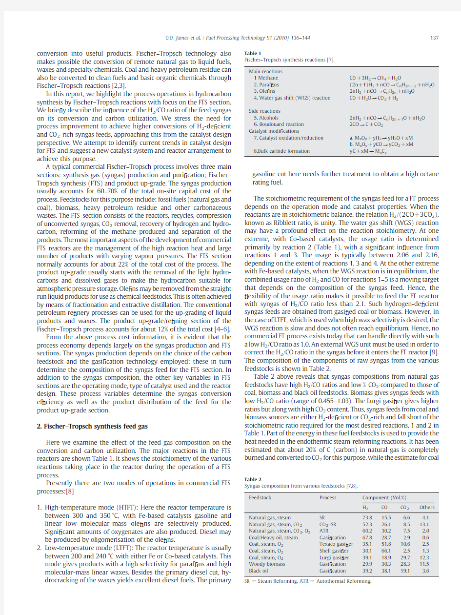
Table2above reveals that syngas compositions from natural gas feedstocks have high H2/CO ratios and low%CO2compared to those of coal,biomass and black oil feedstocks.Biomass gives syngas feeds with low H2/CO ratio(range of0.455–1.03).The Lurgi gasi?er gives higher ratios but along with high CO2content.Thus,syngas feeds from coal and biomass sources are either H2-de?cient or CO2-rich and fall short of the stoichiometric ratio required for the most desired reactions,1and2in Table1.Part of the energy in these fuel feedstocks is used to provide the heat needed in the endothermic steam-reforming reactions.It has been estimated that about20%of C(carbon)in natural gas is completely burned and converted to CO2for this purpose,while the estimate for coal Table1
Fischer–Tropsch synthesis reactions[7].
Main reactions
1Methane CO+3H2→CH4+H2O
2.Paraf?ns(2n+1)H2+nCO→C n H2n+2+nH2O
3.Ole?ns2nH2+nCO→C n H2n+nH2O
4.Water gas shift(WGS)reaction CO+H2O→CO2+H2
Side reactions
5.Alcohols2nH2+nCO→C n H2n+1O+nH2O
6.Boudouard reaction2CO→C+CO2
Catalyst modi?cations
7.Catalyst oxidation/reduction a.M x O y+yH2→yH2O+xM
b.M x O y+yCO→yCO2+xM
8.Bulk carbide formation yC+xM→M x C y
Table2
Syngas composition from various feedstocks[7,8].
Feedstock Process Component(Vol.%)
H2CO CO2Others Natural gas,steam SR73.815.5 6.6 4.1 Natural gas,steam,CO2CO2–SR52.326.18.513.1 Natural gas,steam,CO2,O2ATR60.230.27.5 2.0 Coal/Heavy oil,steam Gasi?cation67.828.7 2.90.6 Coal,steam,O2Texaco gasi?er35.151.810.6 2.5 Coal,steam,O2Shell gasi?er30.166.1 2.5 1.3 Coal,steam,O2Lurgi gasi?er39.118.929.712.3 Woody biomass Gasi?cation29.930.328.311.5 Black oil Gasi?cation39.238.119.1 3.6
SR=Steam Reforming,ATR=Autothermal Reforming.
137
O.O.James et al./Fuel Processing Technology91(2010)136–144
is about 50%due to the much lower hydrogen content.The hydrogen content can be enhanced when the feed gas is reconditioned by mixing with feed gas from steam reforming of methane;but when used directly it implies much of the excess carbon in the feed gas must released as CO 2via WGS.Although,CO 2has low Q -value (hazard quotient)in terms of environmental impact,it is an important greenhouse gas;it also adversely affects the atom economy of the reaction and the process economy at large [10].As a result of these drawbacks,syngas from natural gas feedstocks are often preferred to those from coal and biomass feedstocks.However,fossil reserves are localized in some regions of the world and some countries may have comparative advantage of one kind of fossil reserve over the other.Also,for energy security and other socio-economic/political reasons,a country may adopt FT plant on the basis of its fossil deposits.For example,coal-based FT plants have been in operation in South Africa since 1955,and several other FT plants based on coal are underway (Fig.1).The CO 2emissions and the atom economy of hydrocarbon production via conventional FTS reactions from these plants can thus be imagined.
In the light of the growing concern about global warming and the resulting climate change due to the accumulative emissions of the greenhouse gases from fossil fuels,these emissions can be reduced when biomass is the feedstock for the syngas production.Neverthe-less,the biomass and coal syngas feeds still have the drawback of lower conversion ef ?ciencies because they are either H 2-de ?cient or CO 2-rich.Thus,improving the conversion ef ?ciency of Fischer –Tropsch synthesis with H 2-de ?cient or CO 2-rich syngas is desirable not only to boost the process economy but also for sustainable development [11,12].When it comes to building hydrocarbon chains and achieving high carbon utilization using such syngas feeds without prior reconditioning or a supplementary external source of H 2,it naturally implies forming hydrocarbon with low H/C ratios (<2)i.e.unsaturated and aromatic hydrocarbon that could be suitable as high octane gasoline fuel.Catalysis as an important tool for sustainable industrial chemical processes can be engaged to achieve this https://www.doczj.com/doc/2c10605891.html,rmation from the literature reveals little or no research effort targeted in this direction.In this paper,we appraise studies dealing with catalyst systems and process development in the FT process.We suggest new hybrid catalyst systems to achieve higher conversion ef ?ciencies with H 2-de ?cient and CO 2-rich syngas feeds in Fischer –Tropsch synthesis.We also describe the resultant implication on the product selectivity.
3.CO 2hydrogenation
Here,we look at the possibility of building hydrocarbon from CO 2,the fate and in ?uence of CO 2on FTS using CO 2-rich syngas.Fischer –Tropsch reactions involving CO 2as reactant or as product have a substantial in ?uence in the processes [13,14].The WGS reaction can adjust the molar ratio of H 2/CO to the optimum for hydrocarbon synthesis [15].With catalysts that are WGS reaction active,the product distribution is virtually unaffected.However,catalysts with low WGS reaction activity tend to give product distribution that show more selectivity to methane.Iglesia et al.[16]highlighted the role of the WGS reaction in the pathway for oxygen removal in the FTS using Fe-based catalyst.It was explained that CO 2addition resulted in a reduction in CO 2formation during FTS and oxygen is preferentially removed as H 2O via WGS reaction.This lowers the H 2/CO ratio in the reactor which in turn results in higher C 5+selectivity and ole ?ns content in the product.The authors argued that recycling of CO 2formed during FTS can be used as a tool to improve carbon utilization ef ?ciency when Fe-based catalysts are used.This is an added advantage for iron-based catalysts besides being cheaper and more ?exible than Co-based catalysts [16].
Results from isotopic tracer studies by Iglesia et al.[16]reveals that CO 2is much less reactive than CO and does not compete with CO during FT chain initiation and growth reactions.However,in the WGS reaction,CO and CO 2become kinetically indistinguishable from each other at equilibrium.According to Riedel et al.[17,18],variations in the partial pressures of H 2,CO,CO 2and H 2O have almost no in ?uence on the product distribution when using Fe-based catalysts.The situation is different with a Co-based catalyst (low WGS activity),as they give products that is rich in methane.This suggests that WGS activity is essential in the management of H 2-de ?cient as well as CO 2-rich syngas feeds for FT hydrocarbon synthesis.In another work,Riedel et al.[19]state that the conversion of CO 2-carbon into value-added organic compounds is possible and can be described according to the following reaction:CO 2tH 2?CO tH 2O CO t2H 2→–CH 2?tH 2O
Results obtained by Davis and co-workers from FTS carried out at varying partial pressures of water,with a Fe catalyst and
isotopic
Fig.1.Sasol's current global Fischer –Tropsch activities.
Source:Brian Tait,Sasol ’s Activities on Synthetic Fuels,2nd International BtL Congress,2006.
138O.O.James et al./Fuel Processing Technology 91(2010)136–144
tracer studies pointed in the direction of the same active sites for the FTS and WGS reactions.They postulated that the chain initiation and structure of the active sites for CO2hydrogenation resembles,or is the intermediate for the WGS reaction.They added that the chain growth occurs only from CO and the proposed mechanism is as follows:[20] H2egT?H2eadT
CO2egT?CO2eadT
CO2eadTtH2eadT?COeadTtH2O
CO2eadTtH2eadT?COegTtH2O
COeadTt2H2eadT?–CH2?tH2O
COeadT?COegT
Provided the equilibrium and kinetic barriers can be removed, direct hydrocarbon formation from CO2can occur in principle.For Co-based catalysts,CO2behaves as an inert diluent in syngas feed at temperatures below220°C.In some cases,a negative effect of CO2on CO FT hydrogenation rates can be observed.At a temperature of 220°C,water gas shift activity may also appear with Co as catalyst, besides the increase in methanation rates.
It can therefore be inferred that CO2-rich syngas feeds can be used directly in the FT process,provided the requisite catalytic activities (FTS and WGS)are present in the catalyst.Fe-based catalysts would be self suf?cient in this respect but Co-based catalysts would require promotion with WGS active metals.The use of CO2for building hydrocarbons requires an additional mole of H2per mole of CO2to form the–CH2?.Thus,achieving high carbon utilization using directly syngas feeds from biomass,black oil and coal(Lurgi gasi?er) sources will give rise to the formation of hydrocarbon products with very low H/C ratios i.e.products with predominantly aromatic com-ponents,which could be useful as high octane gasoline or aromatic chemicals.
4.Fischer–Tropsch catalysts
We brie?y highlight the development of catalysts in FTS;we point out the trends in catalyst design and show how the current trend can lead the way to improve the catalyst system to achieve high syngas conversion in FTS with CO2-rich and H2-de?cient syngas feeds.Central to Fischer–Tropsch synthesis technology are the catalysts.A com-mercial catalyst needs to meet strict criteria for activity,selectivity to C5+hydrocarbons,availability and cost.Selectivity considerations are extremely important in the design of the FT section in FT plants. Conventional FT catalysts are usually designed to exhibit high catalytic selectivity to C5+hydrocarbons and low selectivity to C1–C4hydrocarbon products and CO2.Other considerations are catalyst activity,stability and reaction heat management[21,22].
The active FTS metals and their properties as FTS catalysts are presented in Table3.The choice of active metal has important implications on the selectivity and the cost of the FTS catalyst.From the information in Table3,it is clear that cobalt-and iron-based catalyst are commonly used commercially.
The common/conventional FT catalysts are divided into three major classes:fused iron catalysts,precipitated iron catalysts and supported cobalt catalysts.
4.1.Fused iron-based FT catalysts
Here the catalyst is prepared by fusion of the ores of iron(hematite or magnetite)with alkali salt(K or Na).The resulting solid mass is then pulverised to small particle sizes and reduced in a CO or CO2/H2 stream at400–600°C.Fused Fe-base FT catalysts are used in HTFT operations.The preparation procedure is essentially the same over the years with little improvement due to lack of research attention in this area[24].
4.2.Precipitated iron-based FT catalysts
Precipitated iron-based FT catalysts have enjoyed more research attention than the fused-type.Several approaches have been em-ployed in the design of ef?cient precipitation iron FT catalysts.The conventional method is precipitation of the iron from its solution as hydroxide/oxide and subsequent reduction to activate the catalyst [25].The in?uence of activation gas type(CO,H2and syngas)and condition on FTS catalytic activity and selectivity of potassium promoted iron catalyst is summarised in Table4.Activation with CO is the best,based on the parameters considered in Table5.
The introduction of the complimentary basicity effect in the formulation of iron-based FT catalysts has been found to reduce methane selectivities and increase selectivity in favour of the ole?n components.The comparative in?uence of basicity effect of alkali and alkaline earth metals like Ba,Be,Ca,Mg and K on reaction promoted iron catalysts on the reaction parameter is shown in Table5.
The table reveals that the K promoted catalyst gives better desirable reaction parameters on the whole compared to the Group IIA metals promoted catalysts.This justi?es the preferential use of potassium in Fe-FT catalyst formulation or design[27].Similarly the extent of branching
Table3
Properties of the FTS active metals[7–23].
FTS active metal Price ratio Properties
Fe1—Considered suitable for FTS with syngas with
low H2/CO ratio
—Good water gas shift(WGS)reaction activity
Co230—Considered suitable for FTS with syngas with high
H2/CO ratio
—Little water gas shift(WGS)reaction activity(give
H2O as the main bye product with little CO2)
—Give mainly straight chain paraf?ns
Ni250—Considered suitable primarily for methanation
—Form Ni–carbonyl under FTS conditions
Ru31,000—Too expensive
Rh570,000—Too expensive Table4
Effect of activation gas type on the properties of iron-based FT catalysts[26]. Parameter Increasing effectiveness of the reductant gas
CO conversion H2 FTS activity H2 Methane selectivity H2>syngas>CO Alkene selectivity H2 The parameters show little dependency on temperature. Table5 In?uence of promoter(metal)basicity on the properties of iron-based FTS catalyst[27]. Reaction parameter Order FTS activity K>(Ba,Be,Ca,Mg)>un-promoted Carbon utilization K>Ba>Be>Ca≈un-promoted CO2utilization(Ba,Be,Ca,Mg)≈un-promoted>K Methane selectivity Un-promoted>(Ba,Be,Ca,Mg)>K C5+selectivity(Ba,Be,Ca,Mg)>K>un-promoted C1–C4selectivity Un-promoted>(Ba,Be,Ca,Mg)>K C2–C4ole?ns ratio(Ba,Be,Ca,Mg)>K>un-promoted 139 O.O.James et al./Fuel Processing Technology91(2010)136–144 in the FTS product with iron has also been linked to catalyst formulation. High acidity and low hydrogenation strength catalysts will favour branching.Other important components of precipitation iron FT catalysts are structural promoters.They include SiO2,Mn etc.These components are often included in Fe-FT catalyst formulations to improve the mechanical properties and stability of the active sites of the catalyst.Table6shows examples of precipitation iron catalysts and the in?uence of promoters on the product selectivity. 4.3.Supported cobalt-based FT catalysts Due to the price implication of cobalt and in order to maximise the metal effect,cobalt catalysts are usually dispersed on high surface area solid supports such as SiO2,Al2O3,TiO2,and ZrO2.Supported cobalt catalysts are well known for their high FTS activity and selectivity to paraf?n as wax for the LTFT(180–250°C)process.The catalysts are often promoted with small amounts of platinum group metals in order to decrease their reduction temperature and enhance activity and C5+selectivity.Table7is a summary of some effects of promoters on the properties of some Co-based FTS catalysts.The active sites on the catalysts are the dispersed Co-particles.The function of the promoter metals is maintained the Co-particles dispersed during the FT reaction. Table7shows that promoter metals lower the reduction tempera-tures of Co(the FTS active metals)and in?uence the product distribution.The basic metals(La and Mo)increase selectivity in favour of ole?ns.The Pt-group metals promote linear paraf?ns selectivity, while Au and Mn increase selectivities in favour of higher alcohols and methane,respectively.Although the support materials in Co-based catalysts are often considered to have no signi?cant effect on the product distribution,it has been pointed out that the acidity of the support materials can signi?cantly in?uence the product selectivity of the synthesis.According to Bessell,[59]the acidity of the support material can also in?uence the product distribution.Lower acidity support materials,such as SiO2,Al2O3etc.,will give linear hydrocarbon products,while more acidic support materials will exhibit a higher selectivity towards branched and aromatic products.The author argues that acid-promoted isomerisation and aromatization of the FT ole?n will be favoured at high temperature.Thus,a combination of the FT reaction and a process for the conversion of ole?ns to high octane gasoline process can be imagined. 4.4.Supported iron-based FT catalysts Supported Fe-based FTS catalysts are less popular in commercial FT processes.This may be due to the low cost and availability of iron ore and salts,which favour their development as bulk FTS catalysts. Catalyst stability was initially the primary criterion for the choice of support materials in catalyst design for FT processes.Table8 illustrates the suitability of different support materials of Fe-based FT catalysts with respect to the catalyst stability.From the information in the table,Al2O3is adjudged the best for the catalyst based on FTS activity and stability. However,the effect of support materials on the products selectivities of iron-based FTS catalysts reveals a trend in FTS catalyst design,as earlier suggested by Bessell[60]for Co-based FTS catalysts. In the same vein Snell[61–63]highlighted factors affecting the extent of branching in FTS product with iron-based catalysts and commented that branching is a function of catalyst formulation.High acidity and Table6 In?uence of promoters on the product selectivity of precipitated iron catalyst. Catalyst Product selectivity Ref Fe/Cu/K Facilitates reduction of Fe2O3to Fe;increases FT and WGS activities;decreases methane selectivity;and no effect on 1-alkene-2-alkene isomerisation. [28] 100Fe/3Cu/4K/ 16SiO279%syngas conversion,83%C5+selectivity and3%CH4 selectivity.Suitable for slurry reactor. [29] Fe–Zn–Cu–K Lower CH4selectivity than Co-base catalyst;low CO2 selectivity and reduced reduction temperature;high C5+ selectivity,and selectivity weakly affected by temperature and syngas composition. [30] Fe–Mn High activity and light alkenes selectivity.Mn keeps the active sites from sintering. [31] Fe–Mn/K C5+selectivity increases with K loading.[32] Fe–Mn/K Potassium suppresses hydrogenation function,selectivity to ole?ns and methane formation restrained with increasing potassium loading. [33] Fe–Mn/SiO2Incorporation of SiO2increases surface area but weakens surface basicity.Selectivity to C1–C4ole?ns and oxygenates decrease with increasing SiO2content. [34] Fe–Mn/Cu Cu has no effect on catalyst activity but enhances ole?n/ paraf?n ratio and selectivity in favour of heavy hydrocarbon. [35] Fe–Mn/Ca Enhances surface basicity but has no effect on textual properties of the catalyst,reduce FTS and WGS activity, suppress CH4formation but enhance ole?n and C5+ selectivity. [36,37] Fe–Mn/Mg Excess Mg or Ca leads to rapid loss of activity. Fe/SiO2Weakens surface basicity;severely suppresses carburization and CO adsorption to increase C1–C4with C5+selectivity. [38] Fe–Mn–K/SiO2Increases surface basicity and enhances carburization; suppresses methane formation and C12+selectivity,and excess Mn reduces carburization in CO.[39] Table7 Effect of promoters on activity,product selectivity and reduction temperature of Co of supported Co-based FTS catalysts. Promoter Support Activity Product selectivity Effect on reduction temperature Ref Pt Al2O3High Selective to ceresin (wax) Reduced[40] Mn SiO2Increased Higher CH4selectivity Reduced[41,42] Mo SiO2Increased C5+selectivity of85– 90%,increase ole?ns selectivity and reduced CH4selectivity. Reduced[43] La SiO2Increased Decreased CH4and lowered alkanes selectivity Reduced[44–48] Au TiO2Increased Increased methane selectivity Reduced[49] Re TiO2, SiO2, Al2O3 Increased Increased C5+selectivity and ole?n/paraf?n ratio for C2–C4with lower H2/CO ratios. Reduced[50–53] Ru SBA-15, SiO2, γ-Al2O3 Increased Showed higher selectivity to C5–C12hydrocarbons. Reduced[54–56] Zr Al2O3Increased Enhanced C5+selectivity and ole?n/paraf?n ratio. Reduced[48, 57–58] Table8 Effect of different support materials on the properties of supported iron-based FT catalyst[23]. Support Catalyst properties ZrO2—Does form iron zirconate —Low surface area and small pore size SiO2—High surface area and large pore size —Poor attrition resistance —Forms bulk iron(II)silicate Al2O3—High surface area and large pore size —Good attrition resistance —Form bulk iron(II)aluminate. 140O.O.James et al./Fuel Processing Technology91(2010)136–144 low hydrogenation strength of the catalyst will favour branching.He further added that the extent of branching decreased with time on stream and depends on the product carbon number.For catalysts with low hydrogenation strengths,branching will occur preferentially in the lighter products and vice-versa.This fact can be illustrated when we compare product selectivities reported by Adesina and Chen[43] and a recent report by Steen et al.[64],in Fischer–Tropsch synthesis using silica supported molybdenum promoted cobalt catalyst and molybdenum-modi?ed Co/γ–Al2O3catalysts respectively.Adesina and Chen obtained linear hydrocarbon with high alkene selectivity whereas Steen et al.obtained product that is rich in branched com-pounds.It was explained that the increase acidity of the catalyst support strongly in?uenced the Fischer–Tropsch synthesis.The acid sites on Al2O3are stronger than those on SiO2,thus,molybdenum-modi?ed Co/γ–Al2O3has in addition to the FTS active sites,acid sites that are of suf?cient strength to signi?cantly in?uence the product distribution.The presence of the acid sites within the catalyst enhanced the extent of double bond isomerisation,this result in an increase in the amount of branched compounds and a decrease in the chain growth probability.The Table9depicts the effects of support materials on the product selectivities of some Fe-based FTS catalysts. From the above,a new trend in FTS catalyst design can be inferred. This combines the FTS activity with one or more catalytic activities of the product up-grade section.This merging of the operations of the two sections has advantages that include: ?Reduction of the number of process units or unit operations to obtain the desired end product of the FT processes. ?It opens up new ways to improve carbon utilization or conversion of H2-rich or CO2-rich syngas feeds. 4.5.FT catalyst supports as diluents One of the challenges in FTS sections of FT plants is the removal of the heat liberated by the highly exothermic reaction from the reactor, especially?xed-bed reactors.A high reactor temperature in FTS is associated with loss of activity and selectivity due to catalyst sintering, fouling and coking.It has been shown that the use of support materials as catalyst diluents can provide a means of managing the heat liberated in the reactor during the FTS reaction.This idea was demonstrated by Claudia et al.[69].They used SiO2,α-Al2O3and SiC as diluents in an FTS reaction involving Fe/SiO2and Co/SiO2in a?xed-bed reactor.The result obtained showed that the use of diluents increases CO conversion due to improved heat removal from the catalyst bed.It was also observed that the properties of the diluents may have in?uence on the product selectivity.Table10illustrates the observation of Claudia and co-workers[69]. The information in Table10clearly shows that catalyst support materials could play a signi?cant role in FTS reactions.They can improve the feed gas conversion as inert diluents and also affect the product selectivity when they have intrinsic activities.The observed product properties in Table8support this argument.An ASF product distribution is therefore expected from catalyst with inert supports, while a non-ASF product distribution is expected from catalysts with supports that have intrinsic catalytic activities due to simultaneous effects of these activities and the FTS activity of Fe or Co.The inert support(carbon nanotube)gives products with similar distributions as the unsupported ones,while catalysts with support materials with intrinsic catalytic activities give products with distributions different from their unsupported counterparts. 4.6.Hybrid catalyst systems It has been shown from the literature that catalyst supports of FT active metals not only improve the catalytic activity and stability,they also aid heat management in FTS reactions in?xed-bed reactors and also signi?cantly affect the product distribution of the reaction.These facts need to be taken into consideration in FTS catalyst design.This has resulted in the development of hybrid catalyst systems in FTS reactions.The catalyst systems have multifunction activities and are prepared such that: ?The FTS active metal is dispersed on support materials with the desired intrinsic catalytic properties. ?In addition to the FTS active metal,one or more catalytic activities are incorporated on an inert support. ?A physical mixture of the common FTS catalysts and the support with the desired intrinsic properties. ?A physical mixture of the common FTS catalysts and another supported catalyst with the desired catalytic activities. This emerging trend in FTS catalyst design has potentials for making liquid fuels and chemicals through FT technology more economically competitive with those from petroleum.Hence more fundamental studies are required in this area.A few studies in this area show how unprecedentedly high product selectivity can be achieved with hybrid FTS catalysts.The examples in Table11illustrate this point. Therefore,more options are now available to contrive FTS synthesis to selected product ranges in a one-step reaction or reduced unit operations and processes.These options of incorporation of speci?c catalytic activities with FTS activity,and the advantage of the better reaction heat management with diluents,can be exploited to achieve higher syngas conversion of H2-de?cient and CO2-rich syngas feeds.It has been suggested that during FTS,CO2hydrogenation,along with CO, to liquid hydrocarbons can act as a CO2sink.This is one way of disposing of CO2as part of efforts to reduce global warming and also make the process more viable economically[79].Improved carbon utilization in FTS with H2-de?cient and CO2-rich syngas feeds will not only improve the process economy but it is also desired for sustainable development. The major constraint of hydrocarbon build-up in such FTS processes is limited H2gas in the syngas feed.Conventional H2gas production processes are associated with CO2emission and those without Table9 Effects of the support materials on the selectivities of some iron FTS catalysts. Catalyst Product properties Ref Fe/MnO—High WGS activity resulting in high CO2 and reduced methane formation. [65] —High ole?n selectivity and alcohol formation Fe–zeolite–Y—Works well with H2-de?cient syngas feeds[66] —High iso/normal alkane ratio —Ole?n selectivity found to depend on the acidity of the support Fe–K–zeolite(LTL)—Has higher activity and ole?ns selectivity than Fe/SiO2,Fe/Al2O3and Fe/C [67] Fe–Cu–K/C(carbon nanotube)—FTS activity and product distribution similar to those of unsupported [68] —Fe catalysts Table10 Effect of diluent properties on product selectivity in the FTS process[69]. Catalyst Diluent Conversion Selectivity(%) 1/1CO(%)CO2CH4C2–C7>C8 Pure SiO2–00000 Co/SiO2–37.88.98.913.368.9 SiO266.47.2 4.817.770.3 α-Al2O336.712.214.533.340.0 SiC49.28.68.6 2.580.3 Fe/SiO29.360.28.334.1 1.9 9.360.2 3.834.1 SiO213.449.6 4.044.6 α-Al2O318.724.714.055.1 SiC11.145.4 2.127.724.8 141 O.O.James et al./Fuel Processing Technology91(2010)136–144 considerable emissions(using hydroelectricity,solar or nuclear power) have some aspect of cost and risk disadvantages.[80]Another option that has not been considered in this effort is in situ release of H2from already formed hydrocarbon via dehydrogenation or aromatization. This approach can be achieved by taking a clue from the current trend in FTS catalyst design.A hybrid catalyst system with dehydrogenation activity sites incorporated on the catalyst support,together with the FTS active sites or a physical mixture of FTS catalyst and dehydrogenation catalyst,can be employed. In the next section,we explore studies on dehydrogenation catalysts and the reactor catalytic bed arrangements that will be suitable for this application. 5.Dehydrogenation catalyst systems The selective conversion of alkanes to alkenes,alkadiene and aro-matics via non-oxidative routes has bring about the expansion of the range of feedstocks for petrochemicals and fuels.Non-oxidation dehydrogenations of light alkanes(C1–C4)are endothermic reactions. They are thermodynamically unfavourable at moderate temperatures and often lead to the concurrent formation of high molecular weight alkanes and carbon residues,both of which decrease alkene yields.When the equilibrium is favourable for dehydrogenation below the pyrolytic temperature,the use of appropriate catalysts is greatly bene?cial[21]. Many recent studies have explored the oxidative dehydrogenation (ODH)of light alkanes,which offers an attractive route to alkenes,since the reaction is exothermic and avoids the thermodynamic constraints to non-oxidative route by forming water as a by-product.In addition,ODH also has the advantage of eliminating carbon deposition during the reaction,leading to stable catalytic activity.However,with most catalysts tested,the yield of alkenes obtained by ODH is limited by alkenes combustion to C ox(CO and CO2)[81–83]. The conventional catalysts for non-oxidative dehydrogenation and aromatization of alkanes are reduced metals(Ni,Pt,and Pd)on acidic supports(Al2O3,SiO2,Al2O3–SiO2,and C)and metal oxides(Cr2O3, Mo2O3,and V2O5).Temperatures above500°C are usually employed to achieve commercially practical conversions.The required temperature decreases with increasing chain length of the alkanes.The oxides undergo rapid deactivation during the reaction,but oxides deposited on alumina by impregnation are more resistant to rapid deactivation. Alkanes→AlkenestH2 In the1970s,the use of metal-exchanged zeolite(H-ZSM-5)in catalyse dehydrocyclodimerization of alkane was introduced.Since then,there has been sustained interest in this class of zeolite catalysts. It was observed that the zeolite catalysts catalyse the conversion of the light alkanes to aromatics with low selectivity.This was attributed to fast side reactions.But H-ZSM-5catalysts that are uniquely resistant to deactivation at high temperatures and low hydrogen concentrations are required for favourable dehydrocyclodimerisation thermodynam-ics.The exchange of the hydrogen ion in the zeolite with metal ion(Ga, Zn,Pt etc.)was found to increase the rate and selectivity to aroma-tization reactions and to inhibit cracking side reactions which lead to loss of carbon to undesirable products[84–86]. HàZSMà5tmX nt→X mxn=He1?mxnTàZSMà5tHtmxn where X=Ga,Zn,Pt etc. However,the cations also decrease the stability of the zeolite and lead to signi?cantly faster rates of deactivation of the catalyst.The effects of metal ions in H-ZSM-5on the aromatization of light alkanes have been intensely investigated.Some authors argue that the reaction proceeds via a bifunctional pathway requiring a Bronsted acid site and a metal ion site.A combine action of both sites was considered a requirement.It was proposed that the Bronsted site is required to stabilize alkane adsorption and C–H bond cleavage,while the metal ion site disposes the resulting hydrogen atom.The metal ion increases the rate of alkane aromatizations by increasing the rate of recombinative desorption of H-atoms formed in the C–H activation steps.It was initially concluded that the exchanged metal species in the zeolite(X/H-ZSM-5)cannot catalyse the initial alkane dehydrogenation without the simultaneous presence of Bronsted sites of suf?cient strength to activate the C–H bonds of light alkanes[87].In contrast,further investigations revealed that C–H activation is possible in the absence of Bronsted acid sites.Higher turnover rates(dehydrogenation performance)were later reported on Zn/Na-ZSM-5and Co/Na-ZSM-5catalysts.This was attributed to an increased rate of H-atom desorption and lower aromatic selectivities of the catalysts[88].A lowering of the strength of the Bronsted acid sites was achieved by replacing Al3+with Fe3+in the zeolite(ZSM-5)framework,while still retaining the exchange site required for anchoring the exchange metal species.This resulted in a catalyst with an unprecedented performance(active and stable)and selectivity to alkenes.The weaker acidity of{Fe–OH–Si}compared to {Al–OH–Si}was linked with the enhanced selectivity and stability of the catalyst.These weaker acid sites give lower rates for the acid catalysed alkene oligimerization and cyclizations reaction;and consequently, lower yield of aromatics and other organic residues[89]. In a recent report,Iglesia et al.[91]showed that the synthesis of n-alkenes from higher n-alkenes requires rigorous titration of all residual Bronsted acid sites in the zeolite catalyst(Pt/Na-[Fe]ZSM-5) with Cs.The acid sites tend to catalyse alkene isomerisation via a monomolecular pathway.It was added that this new fact has the potential of opening up additional practical routes for the selective syntheses of molecules with applications as precursor to fuel additives and chemical intermediates.This was demonstrated by the formation of isopentenes(three isomers)via dehydrogenation of n-pentane using Pt/Na-[Fe]ZSM-5as catalyst[92].Dehydrogenation reaction occurs on the Pt cluster,followed by skeletal rearrangement of n-pentene on the few weak acid sites present on the[Fe]ZSM-5.An alkene selectivity of above95%,with excellent stability at a low temperature,was obtained in the absence of H2gas co-feeding. From the above reports,large numbers of dehydrogenation zeolite catalysts,with the general formula W/X-[Y]ZSM-5, where W dehydrogenation metal or metal oxide(Pt,Pd,Zn,Co,Fe,Mo etc.) X monovalent metal ion/species(Na+,K+,Li+,Cu+,Ag+etc.) Y trivalent metal ion as a substitute for Al3+(Fe3+,Ga3+,Co3+, Cr3+,Mo3+,Sc3+,Y3+,La3+,W3+etc.) are possible.The Si in the zeolite framework can also be replaced with Ge,Ti,Zr,Ce etc. Table11 Some examples of hybrid FTS catalyst systems and their product selectivity. Catalyst Product properties Ref Co–Ni–ZrO2+ sulphated ZrO2Very high selectivity to C4and isobutene selectivity(10%of the total hydrocarbon product) [70] Cobalt/HZSM-5zeolite Increased selectivity to aromatic and lower hydrocarbons [71] Co–FTS+HZSM-5Improved both the selectivity and the quality of the gasoline product fraction. [72] Co/SiO2+H-ZSM-5Improved selectivity to middle isoparaf?ns[73] Fe–FTS catalyst+ H-ZSM-5zeolite High isoparaf?ns selectivities[74] Fe–H-ZSM-5Selective for high octane gasoline fractions[75] Fe–FTS catalyst+X-ZSM-5 zeolite(X=Ga.Pd) Selective for high octane gasoline fractions[76,77] K/Fe–Cu/AlO x+H-ZSM-5High C2–C4hydrocarbons selectivity(51%) and rich in ole?ns(77%)[78] 142O.O.James et al./Fuel Processing Technology91(2010)136–144 Thus,a large number of dehydrogenation catalysts,with varying Bronsted acid strengths and densities,exhibiting varying selectivities towards alkenes,iso-alkenes and aromatics,can be prepared and investigated for their properties and industrial applications. Process economics requires that a catalyst must increase the rate of a desired reaction while minimizing side reactions.An ef ?cient dehydrogenation catalyst must be highly selective towards the desired reaction.The conventional dehydrogenation catalysts and their improved forms still suffer one or more side reactions and/or stability limitations.In oxidative dehydrogenation,the alkene yields are not thermodynamically limited,because the reaction is exother-mic and the hydrogen atom removed from C –H activation step are directly removed as water.However,alkene yields are limited by sequential and parallel oxidations of C to yield CO and CO 2. In non-oxidative dehydrogenation,high hydrogen gas concentra-tions limit the alkene product yield by increasing the rates of the reverse reactions.Hydrogen selective membranes have been employed by several researchers to drive the equilibrium in favour of alkene formation.Hydrogen removal by selective reaction with co-reactants (such as oxygen)was investigated by Iglesia et al.[90].They reported that alkene yields higher than the equilibrium amount by a factor of about 1.6were achieved.However,co-feeding alkane and oxygen leads to rapid combustion of the alkane.This results in the depletion of oxygen before hydrogen is formed and the dehydroge-nation reaction approaches equilibrium.The authors also reported that high oxygen concentration led to rapid depletion of hydrogen and formation of carbon monoxide.The report concluded that precise control of oxygen introduction,location and rate are vital in order to achieve high selectivity. However,hydrogen removal can also be achieved if an equilibrium reaction involving hydrogen as a reactant is coupled with the dehydrogenation reaction,i.e.,the two reactions take place simulta-neously in the same system under the same conditions.This approach will eliminate the need for co-feeding reactants and drive the dehydrogenation equilibrium in the forward direction.The high iso-butene,iso-paraf ?n,aromatics and high octane gasoline fuel product selectivities reported in Table 11can be attributed to concurrent FTS,dehydrogenation,isomerisation and aromatisation reactions taking place in the catalyst bed.This will be more bene ?cial to the FTS process using H 2-de ?cient or CO 2-rich syngas feed,as the released H 2from the dehydrocyclodimerization or aromatization will couple with the reverse WGS reaction,hydrogenate CO and CO 2to build more hydrocarbons. Alkanes ;Alkenes →dehydrogenation =aromatization Alkenes ;Aromatics tnH 2 nH 2t2n =25CO ;3n =25CO 2→–eCH 2Tn =5?t3n =10H 2O A broad range of combinations of hybrid catalyst systems may therefore be conceived and explored from the large number of variety of conventional dehydrogenation and aromatisation catalysts as well as from the wide option of the dehydrogenation zeolite catalysts described above for the FTS reaction,using H 2-de ?cient or CO 2-rich syngas feeds to achieve high carbon utilization and desired product selectivities in one-step reaction or in reduced unit processes or operations. The maximal carbon utilization envisages with the hybrid catalysts system can be achieved in a reactor catalytic bed such that the primary FTS hydrocarbon products are secondarily dehydrogenated and or aromatized.In order to promote the formation of longer hydrocarbons;a multi-step reaction arrangement will be an advantage toward this effort,that is,a two or three step sequential reactions arrangement through a multiple catalytic bed reactor system.For a two-step reaction,the ?rst catalyst bed should be FT active only followed by the combined FT active and dehydrogenation/aromatization active beds.Here,the ?rst bed will produce the primary products which when passed through the second bed,hydrogen can be squeezed out from the primary products to hydrogenate part of the excess CO/CO 2to build hydrocarbons depend-ing on the syngas feed composition.A three-step reaction system may have the ?rst step catalyst bed to be FT active only followed by dehydrogenation/aromatization active beds and the third step will combine FT active+dehydrogenation/aromatization active beds.Un-like the two-step reaction,here,the primary product formation and hydrogen release reactions are meant to take separately in the ?rst and second catalytic beds and the third bed as combined reaction unit for maximum hydrocarbon formation.6.Conclusion Fischer –Tropsch technology is currently a topical issue in the energy industry.It involves three main sections:syngas production and puri ?cation,Fischer –Tropsch synthesis and product up-grade.The feedstocks for the syngas production are fuels (natural gas and coal),biomass,heavy petroleum residue and other carbonaceous wastes.Coal and biomass feedstocks suffer the drawback of low hydrogen content.Hence syngas feed production from them is associated with poor conversion ef ?ciency and low H 2/CO ratios in the syngas feed produced.The H 2/CO ratios fall short of the stoichiometric requirement for the synthesis of linear hydrocarbons and the excess CO is disposed of as CO 2via the water gas shift reaction.This further reduces the carbon utilization and,consequently,the process economy.Fischer –Tropsch processes using syngas feed from biomass and coal may be desirable from green house gas emission perspective and for social political reasons.A sustainable technology for maximising carbon utilization with such syngas feeds demands H 2production from sources with little or no CO 2emission.Production of H 2through hydel,solar or nuclear power options suffers from either a cost or risk disadvantage.Although previous catalyst and process development efforts were directed toward maximising C 5+selectivity,they are not adequate to achieve high carbon utilization with H 2-de ?cient and CO 2-rich syngas feeds.Current trend in FTS catalyst design hold the potential of achieving high carbon utilization with a high option of selectivities.Acknowledgement Olusola O.James is grateful to TWAS and CSIR (India)for TWAS-CSIR Postgraduate Fellowship Award.James is thankful to Prof.K.O.Okonjo for his assistance and encouragements.He also appreciates the trust placed in him and in this study by T.A.Adeoye (Miss).References [1]A.P.Steynberg,in:A.Steynberg,M.Dry (Eds.),Studies in Surface Science and Catalysis 152:Fischer –Tropsch Technology,Elsevier,Amsterdam,2004,pp.1–10,ch 1. [2]C.Barker,edn 4,Kirk –Othmer Encyclopedia of Chemical Technology,Vol.18,John Wiley &Sons,1996,p.344. [3]I.Kroschwitz,M.Howe-Grant,Kirk –Othmer Encyclopedia of Chemical Technol-ogy,Fourth Edn.Wiley &Sons,New York,1996. [4]G.N.Choi,S.J.Kramer,S.T.Tam,J.M.Fox,N.L.Carr,G.R.Wilson,Coal Liquefaction and Solid Fuels,Pittsburgh,1997. [5]J.H.Gregor,Catalysis Letters 7(1990)317–332. [6]G.N.Choi,S.J.Kramer,S.T.Tam,J.M.Fox,Spring National Meeting,American Institute of Chemical Engineers,Houston,1996. [7]G.P.Vander Laan,Ph.D Thesis,University of Groningen,1999. [8]S.L?gdberg,Ph.D Thesis,KTH School of Chemical Science and Engineering,2007.[9]M.E.Dry,in:A.Steynberg,M.Dry (Eds.),Studies in Surface Science and Catalysis 152:Fischer –Tropsch Technology,Elsevier,Amsterdam,2004,pp.196–205.[10]R.A.Sheldon,Chemtech 24(1994)38. [11]J.D.O'Rear,F.Goede,in:B.H.Davis,M.L.Occelli (Eds.),Fischer –Tropsch Synthesis, Catalysts and Catalysis,Elsevier B.V,Amsterdam,2007,pp.401–409.[12]C.Song,Catalysis Today 115(1–4)(2006)2–32. [13]B.H.Davis,L.Xu,S.Bao,Studies in Surface Science and Catalysis 107(1997) 175–180. [14]B.H.Davis,L.Xu,S.Bao,D.J.Houpt,https://www.doczj.com/doc/2c10605891.html,mbert,Catalysis Today 36(3)(1997) 347–355. [15]D.S.Newsome,Catalysis Reviews.Science and Engineering 21(1980)275–318.[16]E.Iglesia,S.Krishnamoorthy,A.Li,Catalysts 80(1)(2002)77–86. 143 O.O.James et al./Fuel Processing Technology 91(2010)136–144 [17]T.Riedel,H.Schulz,G.Schaub,M.Claeys,S.Walter,Studies in Surface Science and Catalysis114(1998)159–164. [18]T.Riedel,S.Walter,M.Claeys,H.Schulz,G.Schaub,Studies in Surface Science and Catalysis114(1998)443–446. [19]T.Riedel,M.Claeys,H.Schulz,G.Schaub,N.Sang-Sung,J.Ki-Won,C.Myoung-Jae, G.Kisham,L.Kyu-Wan,Applied Catalysis.A,General186(1–2)(1999)201–213. [20]M.Luo,S.Bao,T.Das,B.H.Davis,Fischer–Tropsch synthesis:is a single site responsible for FTS and WGS on iron catalysts?University of Kentucky Centre for Applied Energy Research,2007,Obtained from https://www.doczj.com/doc/2c10605891.html,,24-07-07. [21]M.Roper,Fischer–Tropsch synthesis,in:W.Keim(Ed.),Catalysis in C1Chemistry, D.Reidel,Dordrect,The Netherlands,1983,pp.41–88. [22]B.Jager,M.E.Dry,T.Shingles,A.P.Steynberg,Experience with a new type of reactor for Fischer–Tropsch synthesis,Catalysis Letters7(1990)293–302. [23]M.A.Vannice,Journal of Catalysis50(1977)228. [24]H.Pines,The Chemistry of Catalytic Hydrocarbon Conversions,Academic Press, Inc.,1981,pp.276–283. [25]B.H.Davis,M.Luo,Fuel Processing Technology83(1–3)(2003)49–65. [26]B.H.Davis,M.Luo,Applied Catalysis.A,General246(1)(2003)171–181. [27]B.H.Davis,A.P.Raje,R.J.O'brien,Journal of Catalysis180(1)(1998)36–43. [28]B.H.Davis,E.Iglesia,DE-FC26-98FT.40308,Oct.1–Dec.311998. [29]B.D.Burkur,L.Xiaosu,Industrial&Engineering Chemistry Research38(9)(1999) 3270–3275. [30]E.Iglesia,L.Senzi,S.Krishnamoorthy,L.Anwu,G.D.Meitzner,Journal of Catalysis 206(2002)202–217. [31]H.W.Pennline,M.F.Zarochak,R.E.Tischer,R.R.Schehl,Applied Catalysis21(2) (1986)313–328. [32]L.G.Sergio,M.A.Serbia,R.Baechler,A.Oliveros,J.Orozes,B.Fontal,A.J.Mora,G. Delgado,Reaction Kinetics and Catalysis Letters75(1)(2002)1588–1596. [33]T.Yong,H.W.Xiang,Y.Y.Xu,L.Bai,Y.W.Li,Applied Catalysis21(2)(2004)313–328. [34]Y.Yang,X.Hong-Wei,L.Tian,H.Wang,Z.Cheng-Hua,T.Zhi-Chao,X.Yuan-Yuan, B.Zhong,L.Yong-wang,Applied Catalysis.A,General284(1–2)(2005)105–122. [35]Y.W.Li,C.H.Zhang,Y.Yang,Y.Yong,T.Bo-Tao,L.Tung-Zhen,Z.Hong-Yan,X. Hong-Wei,Journal of Catalysis237(2)(2006)405–415. [36]L.Yong-Wang,Z.Tao,Y.Yang,C.Zhang,L.Ting-zhen,J.Wang,H.Wan,H.Xiang, Catalysis Communications7(12)(2006)1061–1066. [37]L.Yong-Wang,J.Yang,Y.Sun,Y.Tang,Y.Liu,H.Wang,L.Tian,H.Wang,Z.Zhang,B. Xu,Journal of Molecular Catalysis.A,Chemical245(1–2)(2007)26–36. [38]L.Yong-Wang,W.Hai-Jun,W.Bao-Shan,T.Zhi-Chao,L.Ting-Zhen,A.Xia,X.Hong- Wei,Journal of Molecular Catalysis.A,Chemical260(1–2)(2006)255–263. [39]L.Yong-Wang,L.Tingzhan,Y.Yang,Z.Chenghua,A.Xia,H.Wan,Z.Tao,X.Hong- Wei,F.Yi,B.Xu,Fuel86(7–8)(2007)921–928. [40]B.H.Davis,J.A.Chaney,P.M.Patterson,T.K.Das,J.C.Maillot,G.Jacobs,Journal of Synchrotron Radiation115(2004)414–422. [41]D.K.Chakrabarty,D.Das,G.Ravichandran,Applied Catalysis.A,General131(2) (1995)335–345. [42]B.M.Weckhuysen,F.Morales,M.F.Frank de Groot,O.L.J.Gijzeman,Mens Ad,O. Stephan,Journal of Catalysis(2005)301–308. [43]A.A.Adesina,H.Chen,Applied Catalysis.A,General112(2)(1994)87–103. [44]S.Vada,A.M.Kazi,F.K.Bedu-Addo,B.Chen,J.G.Goodwin Jr,Studies in Surface Science and Catalysis81(1994)443–448. [45]G.J.Haddad,B.Chen,J.G.Goodwin Jr.,Journal of Catalysis160(1)(1996)43–51. [46]G.J.Haddad,B.Chen,J.G.Goodwin Jr.,Journal of Catalysis161(1)(1996)274–281. [47]M.Adachi,K.Yoshii,Y.Z.Han,K.Fujimoto,Bulletin of the Chemical Society of Japan 69(6)(1996)1509–1516. [48]Y.Ding,T.Wang,Y.Lü,H.Zhu,L.Lin,Journal of Natural Gas Chemistry17(2) (2008)153–158. [49]N.J.Coville,K.Jalama,D.Hildebrandt,D.Glasser,L.L.Jewell,J.A.Anderson,S. Taylor,D.Enache,G.J.Hutchings,Topics in catalysis44(1–2)(2007)129. [50]B.H.Davis,G.Jacobs,T.K.Das,Y.Zhang,J.Li,G.Racoillet,Applied Catalysis.A, General233(1–2)(2002)263–281. [51]B.H.Davis,J.Li,G.Jacobs,Y.Zhang,T.Das,Applied Catalysis.A,General223(1–2) (2002)195–203.[52]B.H.Davis,T.K.Das,G.Jacobs,P.M.Patterson,W.A.Conner,J.Li,Fuel82(7)(2003) 805–815. [53]A.Y.Khodakov,J.Hong,P.A.Chernavskii,W.Chu,Catalysis Today140(3–4)(2009) 135–141. [54]B.H.Davis,G.Jacobs,J.A.Chaney,P.M.Patterson,T.K.Das,Applied Catalysis.A, General264(2)(2004)203–212. [55]A.K.Dalai,A.Tavasoli,M.Irani,R.M.M.Abbaslou,M.Trépanier,The Canadian Journal of Chemical Engineering86(6)(2008)1070–1080. [56]J.Li,H.Xiong,Y.Zhang,K.Liew,Fuel Processing Technology90(2)(2009)237–246. [57]G.R.Moradi,M.M.Basir,A.Taeb,A.Kiennemann,Catalysis Communications4(1) (2003)27–32. [58]J.Li,H.Xiong,Y.Zhang,K.Liew,Journal of Molecular Catalysis.A,Chemical231(1–2) (2005)145–151. [59]S.Bessell,Applied Catalysis.A,General126(2)(1995)235–244. [60]S.Bessell,Applied Catalysis.A,General96(2)(1993)253–268. [61]R.Snel,Applied Catalysis37(1988)35–44. [62]R.Snel,Journal of Molecular Catalysis50(1)(1989)103–114. [63]R.Snel,Journal of Molecular Catalysis53(1)(1989)129–141. [64]E.V.Steen,E.L.Viljoen,J.V.de Loosdrecht,M.Claeys,Applied Catalysis.A,General 335(1)(2008)56–63. [65]K.M.Kreitman,M.Baerus,J.B.Butt,Journal of Catalysis105(2)(1987)319–334. [66]J.Zwart,J.Vink,Applied Catalysis33(2)(1987)383–393. [67]S.G.Marchetti,M.V.Cagnoli,N.G.Gallegos, A.M.Alzarez,J.F.Bemgoa,M.S. Yeramian,Applied Catalysis.A,General230(1–2)(2002)169–176. [68]J.N.Coville,M.C.Bahome,L.L.Jewell,D.Hildebrandt,D.Glasser,Applied Catalysis. A,General287(1)(2005)60–67. [69]L.B.Claudia,C.Pirola,V.Ragaini,Catalysis Communications83(2006)81–99. [70]O.I.Raphael,Energy Fuel14(5)(2000)1072–1082. [71]G.Calleja,A.De Lucas,R.V.Grieken,Applied Catalysis68(1)(1991)11–29. [72]F.G.Botes,W.B?hringer,Applied Catalysis.A,General267(1–2)(2004)217–225. [73]Y.Yoneyema,H.Jingjiang,Y.Morii,S.Azuma,T.Noritatsu,Catalysis Today104(1) (2005)37–40. [74]N.Tsubaki,H.Jingjiang,Z.Liu,Y.Yoneyama,N.Nishiyama,Chemistry—A European Journal12(32)(2006)8296–8304. [75]M.A.Marvest,M.Sohrabi,P.S.Zarrin,G.Baghmishch,Chemical Engineering& Technology28(1)(2005)78–86. [76]A.Martínez,C.López,Applied Catalysis.A,General294(2)(2005)251–259. [77]A.Martínez,C.López,E.Peris,A.Corma,Studies in Surface Science and Catalysis 158(2005)1327–1334Part2. [78]J.Ki-Won,L.Yun-Jo,P.Jo-Yong,J.W.Bae,N.Viswanadham,Catalysis Letters126 (1–2)(2008)149–154. [79]S.Srinivas,R.K.Malik,S.M.Mahajani,Energy for Sustainable Development11(4) (2007)66–71. [80]D.Simbeck,E.Chang,Hydrogen supply:cost estimate for hydrogen pathways scoping analysis,NREL/SR540–32525,,2002No.ACL-2-32030-01. [81]F.Cavani,N.Ballarini,A.Cericola,Catalysis Today127(1–4)(2007)113–131. [82]J.M.L.Nieto,P.Botella,P.Concepcion,A.Dejoz,M.I.Vazquez,Catalysis Today91–92 (2004)241–245. [83]L.M.Madeira,M.F.Portela,Applied Catalysis.A,General281(1–2)(2005)179–189. [84]E.Iglesia,J.A.Biscardi,Physical Chemistry Chemical Physics1(1999)5753–5759. [85]E.Iglesia,J.A.Biscardi,Journal of Catalysis182(1999)117–128. [86]E.Iglesia,W.Ding,G.D.Meitzner,D.O.Marler,Journal of Physical Chemistry.B105 (2001)3928–3936. [87]E.Iglesia,W.Li,Y.Y.Sara,G.D.Meitzner,J.Phys.Chem.B(2001)105,1176–1184. [88]E.Iglesia,Y.Y.Sara,G.J.Yu,W.Li,Journal of Physical Chemistry.B106(2002) 4714–4720. [89]E.Iglesia,T.Waku,J.A.Biscardi,Chemical Communications(2003)1764–1765. [90]E.Iglesia,J.A.Biscardi,T.Waku,Journal of Catalysis222(2004)481–492. [91]E.Iglesia,X.Li,Chemical Communications(2008)594–596. [92]E.Iglesia,X.Li,Journal of Catalysis255(2008)134–137. 144O.O.James et al./Fuel Processing Technology91(2010)136–144 指纹考勤机使用操作步骤 对于新购机用户,可按此操作步骤来操作使用该机器。 本操作步骤将按照采集指纹、设置排班、报表查询、系统管理四个部分进行介绍。 一、采集指纹 新购机用户需要学习如何采集指纹,指纹采集完成后即可正常使用考勤机。 1.把考勤机通电,打开机器,使机器处于正常工作状态。 2.在考勤机操作面板上按主菜单[MENU] – [用户管理] – [用户登记] – [指纹登记],屏幕提示“新登记?” ,按[OK]键,这个时候要输入员工的工号,输入后按[OK]确认,此时屏幕提示:“请放手指”。 3.放手指时要注意,被采集者身体相对考勤机要站正。把从指尖开始2/3位置指肚非常饱满的平放在采集器玻璃片上,不要滑动手指,轻轻用力按压,听到“嘀”的一声移开手指,同样进行第2次第3次按压,按压3次为采集了一枚完整的指纹。 4.3次按压完成后,按[OK] 保存。此时屏幕提示:…新登记??我们可按[ESC] 键,进行备份登记,每个员工可以采集至少2枚指纹,以备其中一个有磨损破裂时使用。 5.备份完成后,按[OK] 保存,此时屏幕提示:“继续备份吗?”如果要继续进行备份请按[OK],要结束备份请按[ESC] ,并进行下一个员工的指纹登记。 6.指纹登记完成后,即可使用所登记的手指进行指纹考勤。依照采集指纹时的按压方法进行即可。按压后,屏幕显示员工的工号,并伴随有机器语音提示“谢谢”。如果按压不成功,则有语音提示“请重按手指”,此时请重新按压手指或更换另一手指按压。 7.在上面第6步操作中,我们只看到了员工的工号,没看到姓名,实际上是可以显示员工的姓名的。请进行以下步骤。 8.在计算机上安装考勤管理系统。放入安装光盘,按屏幕提示进行安装即可,注意要把程序安装路径更改为D盘。 9.把考勤机和计算机进行连接。考勤机和计算机的通讯方式有RS232、RS485、TCP/IP、USB数据线4种直连方式。 10.打开考勤管理系统,选种设备名称及相应的连接方式,点[连接设备]按钮。见下图: 连接成功后,右下放状态栏有提示;且设备名称前的图标为亮彩色显示。 11.点[从设备下载人员信息] 按钮,将弹出窗口,并点[下载]即可。下载完成后请关闭该窗口。 12.点[人员维护] 按钮,则弹出人员维护窗口,如下图: 在上图窗口中,输入员工的姓名信息,并保存。员工姓名输入完毕后请关闭该窗口。 13.点[上传人员信息到设备] 按钮。在弹出的窗口中,按[上传] 即可。此一步是把刚才输入的员工姓名上传到考勤中,上传完毕,按压指纹考勤时即可同时显示员工的工号和姓名了。 至此,指纹的采集工作已经完成。可以把考勤机安放在指定位置进行考勤使用了。接下来我们要讲一下有关部门的设置和员工的调动。 目录 1同方系统还原卡MAX版安装流程图 (2) 2 同方系统还原卡MAX版及操作系统的安装 (3) 2.1安装前的准备 (3) 2.2安装发送端 (4) 2.3网络拷贝 (15) 2.4硬盘复制 (20) 3 自动维护 (22) 4 系统设定 (25) 4.1密码设定 (25) 4.2参数设定 (26) 4.3分区信息 (28) 4.4工具 (28) 4.5重新分区 (29) 4.6更版 (29) 4.7移除 (29) 4.8版本信息 (29) 5 同方易教使用方法 (30) 5.1.系统安装要求 (30) 5.2.软件安装 (31) 5.3.同方易教控制端说明 (32) 5.4.软件分发功能 (39) 6 自动分配IP操作流程 (47) 附录一热键提示 (50) 附录二硬盘大传小功能 (51) 附录三LINUX系统安装说明 (51) 附录四网域登录使用方式 (56) 附录五常见问题解答 (59) 1同方系统还原卡MAX版安装流程图 2 同方系统还原卡MAX版及操作系统的安装 首先非常感谢您使用同方产品。同方系统还原卡MAX版能大批量地完成整个计算机机房系统及软件的安装或更新。先将一台安装好同方系统还原卡MAX版系统、操作系统及应用软件的计算机设定为发送端,其余所有的计算机利用同方系统还原卡MAX版附带的SNCOPY网络联机拷贝盘设定为接收端,通过网络将发送端的硬盘数据同时复制到所有的计算机中,并自动修改所有计算机的IP地址等网络设置,完成整个计算机机房系统的安装和更新。 2.1 安装前的准备 安装本系统前,请您确认以下相关事项: 1、请进入您计算机CMOS管理界面 1)将CMOS中的病毒警告关闭。 2)将CMOS中显卡以外的映射地址设为Disable。 3)将CMOS中的Network/LAN引导选项,设为Enabled 或设定为网络优先启动(该项没有,可以不设定)。 4)如CMOS中有Fast Boot的选项,请将此项设定为 Disable(该项没有,可以不设定)。 2、如需安装Windows NT Workstation,需安装NT补丁程 序Service Pack3以上版本。 3、如需安装两个以上的操作系统,请注意:DOS和Windows NT4.0 Workstation系统只能安装在硬盘物理容量前2GB 以内。 4、本系统不支持Microsoft操作系统的Server版本。 中控考勤机说明书 1考勤机的使用 1.1登记指纹 1.2考勤机功能介绍(通讯,参数设置,系统信息,U盘管理) 2考勤软件的使用 2.1 软件的安装 2.2 软件使用 2.2.1 增加设备 2.2.2 从设备下载人员信息 2.2.3 修改人员信息(改名字,调动部门等) 2.2.4 上传人员信息到设备 2.2.5 下载考勤数据 2.2.6 时间段设置 2.2.7 班次管理 2.2.8 人员排班 2.2.9 统计报表 页脚内容1 一考勤机快速使用 1.1登记指纹(分彩屏跟黑白屏) 从设备上采集指纹: (1)彩屏:长按M/OK键--“用户管理”点OK--“新增用户”点OK--选择工号,- 往下翻在“指纹登记”上点OK,同一个手指按三次,完成后再点击OK键,再放上另一个手指按三次--往下翻到完成上点OK。(如果要再登记指纹可在‘用户管理‘点OK--’管理用户‘点M/OK---点M/OK选择’---- 查找用户‘—输入工号点OK—点M/OK选择“编辑用户”然后选择登记指纹,登记完成后---往下翻到完成上点M/OK。 (2)黑白屏录指纹的跟彩屏类似就不再说了。录备用指纹的话跟彩屏有点区别:按M/OK—用户登记—指纹登记—提示新登记—按ESC键—跳出备份登记—输入工号—登记指纹。。 1.2机器的功能介绍 (1)通讯设置—设置通讯方式有RS232/485通讯,TCP/IP,USB通讯 (2)系统设置—参数设置(包含提示声音,键盘声音,时间设置算法切换(高端机器如iclock360, S20等)--数据维护(删除考勤机上的记录数据【记录要定时去删除】,清除管理权限【管理员破解】,清除全部数据----恢复设置(恢复出厂设置【不会删除考勤机上的数据只是恢复机器出厂的通讯设置等】; (3)系统信息—可以查看设备的人员登记数跟指纹数及考勤记录数-------设备信息可以查看设备的序列号、算法版本、MAC地址、出厂时间等。 (4)U盘功能(包含下载跟上传的功能) <1>(1)把U盘插到考勤机上--长按M/OK键进入菜单--选择U盘管理--下载数据--下载用户数据--下载完成后退出然后把U盘拿下来插到电脑上。 页脚内容2 指纹考勤机如何连接考勤机软件? 指纹考勤机怎么和电脑连接安装,你首先要弄清楚指纹考勤机本身有什么通讯接口,一般指纹考勤机连接有以下接口:USB线,RS232/485(串口),TCP/IP(RJ45口)等几种; 那么电脑软件中也相应的有以上三种通讯方式。买串口或USB口指纹考勤机,里面一般都自带有RS232线和USB线; 1、如果你的考勤机是USB口的,把USB线分别插 入考勤机和电脑USB口,打开软件,选择USB连接方式,就可以成功; 2、以此类推,如果是串口或网线接口,设置一下相关参数,打开软件,选择串口或网线接口连接方式,就可以连接成功了。 指纹考勤机怎么导出打卡记录? 前提是你已经安装好了软件,软件中有人员资料 1、因为H10是用USB线下载数据的,所以首先你要在考勤软件中“设备维护”那里把考勤机与软件的“通讯方式”设置为USB下载后,然后保存。 2、再把考勤机通电,把USB线插入考勤机中和电脑USB接口,再选择“我的设备列表”中“U SB连接方式”,再点连接设备,稍等几秒后,设备连接成功,同时设备名称的圆圈会变成彩色,同时右下角系统会提示连接成功字样。这时,考勤机与电脑软件连接成功了。 3、连接成功后,点“从设备下载记录数据”,这时考勤机里的数据就会通过数据线上传到软件中,同时有下载多少条记录的提示,这时,你点“出勤记录”就可以看见你刚才下载的所有人员记录数据。 打卡机考勤管理系怎么用? 1、你首先把部门资料、人事资料,这些资料全部弄好(包括员工编号、姓名、卡号、部门、就职日期等等) 2、再把公司上班下班的作息时间定义好,考勤规则班次设置好,人员班次分配好 3、以上弄好后,员工上下班打卡,从打卡考勤机导出来的考勤数据记录,进行数据统计,统计完成后,你就可以看考勤明细表,考勤日报表、考勤汇总表、考勤异常表,加班统计表,请假汇总表等。 小哨兵还原卡图文说明 [版权宣告] 小哨兵科技有限责任公司有权随时更改本手册的内容,恕不另行通知。除非另外注明,否则本手册范例中所使用的公司、人名,以及数据都是虚构的。没有小哨兵科技有限责任公司的许可,您不得为任何目的而使用任何形式或方法(包括电子的或机械的),复制或传送本手册的任何部分。 小哨兵科技有限责任公司对于其应用程序、商标、版权或文件中所涵盖的其他知识产权拥有或正在申请专利中。除非取得小哨兵科技有限责任公司的任何书面授权合约,否则不得擅用本手册中的这些专利、商标、版权或其他知识产权。 本手册为通用手册,产品规格如有变更,恕不另行通知。 版权所有?2002小哨兵科技有限责任公司 [用户须知] 本手册同时可适用于小哨兵网吧专用卡,详情请见附录部分。 本手册适用于7.0及以上版本。 目录 第一章产品简介........................................ 错误!未定义书签。第二章主要功能特点................................ 错误!未定义书签。第三章系统需求…………………………………………………第四章安装指南…………………………………………. 4.1安装前的准备工作.......................................................................... 4.2驱动程序的安装.............................................................................. 4.3还原卡的安装.................................................................................. 第五章使用指南............................................................................ 5.1数据恢复.......................................................................................... 5.2参数设置.......................................................................................... 5.3设置管理员口令 ............................................................................. 5.4备份CMOS数据………………………………………………… 5.5更新硬盘数据…………………………………………………… 5.6软盘升级…………………………………………………………. 使用清华同方还原卡的计算机,若需重装系统。 处理: 1)开启计算机后,在出现硬盘保护卡启动界面时,按“F10”进入“系统设定”选项,不需要密码,直接“回车”进入; 2)进入设定后选择到“分区信息”项目,将第一行硬盘分区的“自动复原”属性选中,向上选为“从不复原”,即取消了对硬盘第一分区“C”盘的保护,按“ESC”选择保存并退出重启,此时可以安装各类软件,驱动,优化系统等。 另一种方法:进入bios,清华同方BIOS的通用口令:thtfpc 依次进入--INTEGRA TED PERIPHERALS---ONBOARD DEVICE ----ONBOARD LAN:CONTROLLER 此项设为ENABLED(集成网卡生效) ----ONBOARD LAN:BOOT ROM 此项设为DISABLED(取消还原功能)。 远程教育培训资料之——清华同方系统还原卡的操作 远教2008-03-15 16:39 阅读2909 评论4 字号:大中小 (一)、功能及用途 同方系统还原卡能大批量地完成整个电脑机房系统的安装或更新。 先将一台已安装好同方系统还原卡、操作系统及应用软件的电脑设为发送端,其余所有的电脑设为接收端,通过网络利用网络拷贝工具将发送端的硬盘数据同时复制到所有的电脑中,并自动分配修改所有电脑的IP地址等网络设置,完成整个电脑机房系统的安装或更新。 总结起来也就是二大功能:硬盘维护和网络同传 (二)、还原卡的性质 我们使用的清华同方的还原卡是软还原卡 也有一部分还原卡是硬件的还原卡 如:2003 年以前的还原卡大部分是硬件的还原卡 与常见的还原软件(如还原精灵)相比有许多相似之处但也有其自身的特点 (三)、还原卡所处位置 还原卡不是装在硬盘中,而是装在CMOS芯片中的,但有一种情况除了在CMOS中装一次外,还要在操作系统中装一次,那就是网络同传需要自动分配IP的时候(后边有详细介绍)(cmos中的安装相当于安装了硬件设备,而操作系统中的安装相当于安装了管理硬件的软件——驱动) (四)、还原卡安装前的准备 将所有电脑的CMOS中的病毒警告关闭 请将CMOS中的引导选项设置为Network/LAN选项。 将网线、集线器与计算机全部连接 发送端计算机与接收端计算机的硬件配置必须完全相同 (五)、安装还原卡 1、从学生用机中选择一台计算机,开机,出现"第一次安装"界面。 2、将随机的还原卡光盘放进光驱。 3、选择“本机安装”,有三个选项: 指纹考勤机使用的基本操作方法: 一、人事考勤管理软件系统操作流程: 1、部门定义(输入部门资料) 2、员工录入(建人事档案)---数据下发 3、作息时间定义--考勤规则定义---考勤规则分配 4、请假登记、外出登记、调休登记等 5、员工按照公司上下时间打卡 6、采集数据 7、考勤统计 8、查看考勤明细表、汇总表、日报表及其它报表 二、指纹机安装说明 指纹考勤机硬件安装比较简单,安装时,要配一个220V的电源插座,以便给指纹考勤机供电。 三、指纹考勤机软件操作方法 1、软件使用操作方法流程 a、在―部门表‖那里输入公司所有部门名称 b、在―人员维护‖那里,选择部门,输入每一个人的资料。输入资料时,登记号码那里的号码前面不能添加0 c、在―时间段维护‖ 那里定义好公司上下班的作息时间,在―班次管理‖那里设置好所有人员上班班次,再在―人员排班‖那里把每个人进行排班或进行临时排班 d、员工按上班时间打卡 e、把考勤软件连接指纹考勤机,下载考勤打卡数据,进行统计分析,就可以查看每个月的明细表和汇总表了 四、指纹考勤机操作方法 1.把考勤机通电,打开机器,使机器处于正常工作状态。 2.在考勤机操作面板上按主菜单[MENU] – [用户管理] – [用户登记] – [指纹登记],屏幕提示―新登记?‖ ,按[OK]键,这个时候要输入员工的工号,输入后按[OK]确认,此时屏幕提示:―请放手指‖。 3.放手指时要注意,被采集者身体相对考勤机要站正。把从指尖开始2/3位置指肚非常饱满的平放在采集器玻璃片上,不要滑动手指,轻轻用力按压,听到―嘀‖的一声移开手指,同样进行第2次第3次按压,按压3次为采集了一枚完整的指纹。 4.3次按压完成后,按[OK] 保存。此时屏幕提示:?新登记?‘我们可按[ESC] 键,进行备份登记,每个员工可以采集至少2枚指纹,以备其中一个有磨损破裂时使用。 5.备份完成后,按[OK] 保存,此时屏幕提示:―继续备份吗?‖如果要继续进行备份请按[OK],要结束备份请按[ESC] ,并进行下一个员工的指纹登记。 6.指纹登记完成后,即可使用所登记的手指进行指纹考勤。依照采集指纹时的按压方法进行即可。按压后,屏幕显示员工的工号,并伴随有机器语音提示―谢谢‖。如果按压不成功, 1开机,待出现的表格刚一结束,马上按住Ctrl+F10,出现输入密码选项,输入密码(默认为manager),进入还原卡管理界面,选择“移除还原卡”,确定,然后按提示操作即可。 2启动时按HOME键激活还原卡设置程序卸载就可以了 硬盘保护克星使用说明 使用说明: 1、本软件用于破解市面上绝大多数各种类型的硬盘保护卡、系统还原卡, 还原精灵等,破解速度极快。 2、本软件可运行在所有的Windows平台,包括Windows 95/98/ME/2000/xp/2003等。 3、本软件也可运行在纯DOS环境和Windows 3.x下。 4、启动软件后,请正确选择要操作的硬盘和操作方式,再点“确定”,等待 几秒后,重新启动机器即可。 5、如选择“仅破解保护卡”,重启机器后,绝大多数硬盘保护卡将失去作用, 您可以对硬盘保护卡重新设置所有设置,包括密码。 6、如选择“快速格式化硬盘”,不管机器中是否插有硬盘保护卡, 均可用于对硬盘清除所有分区信息,使硬盘快速完全恢复出厂设置。 7、如选择“完全格式化硬盘”,此方式与“快速格式化硬盘”方式类似, 但所需时间很长,除非“快速”方式无效,才采用这种方式,一般不需要使用。8、因软件采用了特殊方法读写硬盘,所以在软件使用过程有可能出现程序失去响应、系统蓝屏、死机等情况,属于正常现象,只需重启机器即可。 9、系统中如装有GRUB、LILO、等启动管理软件请勿使用本软件。 联想硬盘保护卡的密码 默认的是000000 但是要是改了以后就不一定了 这个东西很特别你要是想进到安装软件模式的话那么你必须有准备就是你以前没有进到安装模式下的C:里的东西全部都没有就算是数据恢复也很难找回来的 所以希望慎重最好是把里面的东西倍份出来以后再做这样的操作 于破解还原卡(通用)请大家先看看后面的(可以穿透还原卡和还原软件的代码) 方法一: 开机时(也就是在你曾经进入cmos的时刻),同时按住ctrl+home,这样你就进入了还原卡的密码输入窗口,只要输入正确的密码即可获得admin,以后随你怎样设置. 关于是密码的问题:一般还原卡都有默认密码的,默认密码怎么找,很简单,到网上搜索QQ:9750406 关键词"还原卡"就行了,找到你用的那个牌子的还原卡,进入站点,在一个比较偏僻的角落一般可以找到默认密码的. 而一般机房管理员是不会修改其默认密码的,比如俺学校的 台湾远志牌的还原卡的默认密码是12345678, 小哨兵的是manager, 机房管理员一个也没改,好爽!!!!!!!!!! 不过我可没破坏任何东东,一旦惹怒了俺,嘿嘿....俺也不会破坏的, 恶意破坏计算机就是对自己的不尊重!!!! 如果管理员把密码改了呢?那就拿出宝刀--- 长按M/OK键进入菜单。选择“部门设置”,按OK键进入 长按M/OK键进入菜单。选择“用户管理”→“新增用户”(按OK键进入):登记完用户按OK键保存。 长按M/OK键进入菜单,选择“排班设置”→“考勤规则”(按OK键进入): 排班方式可选择按部门排班和按个人排班,对未排班部门或个人使用默认班次。 长按M/OK键进入菜单,选择“排班设置”→“班次管理”(按OK键进入): 班次1为09:00—18:00一天考勤2次; 班次2为09:00—12:00;13:00—18:00一天考 勤4次。其它班次可自行设置。 按▲/▼键移动光标到要设置的项,使用T9输入法输 入班次名称,按数字键输入上下班时间。 长按M/OK键进入菜单,选择“排班设置”→“排班”(按OK键进入): 当考勤规则中选择按部门排班时: 按▼键选择要编辑的部门,再按选择班次,按OK键保存退出 按OK键 当考勤规则中选择按个人排班时: 自助考勤终端入门指南 版本:4.0 工号:按数字键输入工号(最长9位)后,按▼ 姓名:使用T9输入姓名后,按▼ 指纹:按“OK”键后进入指纹登记界面,将同一 手指按压指纹采集器三次,按▼ 密码:输入1-8位数字密码,可不设置 部门:按键从列表中选择部门,按▼ 权限:按选择权限,可登记管理员 二、登记用户 三、设置考勤规则(如果使用默认规则,则不需要设置) 四、设置班次(如果使用默认班次,则不需要设置) 五、给员工排班(如果使用默认规则,则不需要设置) 按▲/▼键移动光标到要设置的项。如果是输 入框,按数字键输入要设置的值;如果是滚动框, 按/键切换要设置的值,设置完毕后直接按 “OK”键即可保存设置并返回上一界面,按“ESC” 取消设置并返回上一界面。 一、设置部门(如果使用默认部门,则不需要设置) 设备默认的6个部门可按OK键进去修 改。 按数字键“3”进入新增部门界面,用 T9输入法(详情参见第4页说明)输入部门 名称后,按OK键保存。 指纹考勤机安装设置及使用说明常见问题及解答 (由深圳市全易通科技有限公司提供) 很多使用者对于指纹考勤机的安装设置及使用说明不是很了解,有时在工作中经常遇到各种难题,不知道如何操作设置指纹考勤机,全易通列出以下关于指纹考勤机常见问题及解答,以供大家参考,让大家在使用指纹考勤机的过程中能轻松地管理好指纹考勤机。 一、问:如何使用考勤机的使用寿命更长呢? 答:全易通考勤机温馨提示你: 任何产品都需要保养,考勤机也是一样的。好的维护保养才能让考勤机寿命更长,怎么让考勤机寿命长一点?要有以下理念: 1、选择适合自己公司的考勤机,考勤机有感应卡考勤机、指纹考勤机。当然感应卡考勤机的寿命要比指纹考勤机的长,因为感应卡考勤机是射频的,非接触式的。指纹机是接触式的,有磨损 2、不要放在太阳下曝晒,太阳曝晒会损坏考勤机的液晶屏,使考勤机外壳老化得快 3、最好是给考勤机“穿衣”,安装在保护罩内,可以防尘。起保护作用。 4、不能恶意破坏考勤机,不能用重物敲击考勤机 5、不要在考勤机上外接其它不名可能损坏考勤机的设备。 更多详细了解,请登录全易通考勤机官网了解一下 二、问:指纹考勤机如何连接考勤机软件? 答:全易通指纹考勤机提示你: 指纹考勤机怎么和电脑连接安装,你首先要弄清楚指纹考勤机本身有什么通讯接口,一般指纹考勤机连接有以下接口:USB线,RS232/485(串口)TCP/IP(RJ45口)等几种 那么电脑软件中也相应的有以上三种通讯方式。买串口或USB口指纹考勤机,里面一般都自带有RS232线和USB线1、如果你的考勤机是USB口的,把USB线分别插入考勤机和电脑USB口,打开软件,选择USB连接方式,就可以成功 2、以此类推,如果是串口或网线接口,设置一下相关参数,打开软件,选择串口或网线接口连接方式,就可以连接成功了 更多详细了解,请登录全易通考勤机官网了解一下 三、问:考勤机连接不上是什么原因? 答:全易通指纹考勤机提示你: 考勤机下载不了新的考勤信息?一个最主要原因,就是考勤机与电脑之间的线路有问题。以下其它的原因也不可忽视 1、考勤软件中通讯方式设置有可能更改 2、如果是通过RS485方式连接的,有可能是RS485转换器坏了,也有可能是电脑串口有问题 3、如果是通过TCP/IP连接,有可能是公司交换机或路由器有问题,启动一下公司的交换机或路由器有问题,再连接一下,就可以了(这个情况我们客户发生过) 4、如果是USB线或RS232线连接,可能是USB线或RS232有问题 远程教育培训资料之——清华同方系统还原卡的操作?同方系统还原卡能大批量地完成整个电脑机房系统的安装或更新。 先将一台已安装好同方系统还原卡、操作系统及应用软件的电脑设为发送端,其余所有的电脑设为接收端,通过网络利用网络拷贝工具将发送端的硬盘数据同时复制到所有的电脑中,并自动分配修改所有电脑的IP地址等网络设置,完成整个电脑机房系统的安装或更新。 总结起来也就是二大功能:硬盘维护和网络同传?(二)、还原卡的性质?我们使用的清华同方的还原卡是软还原卡?也有一部分还原卡是硬件的还原卡?如:2003 年以前的还原卡大部分是硬件的还原卡?与常见的还原软件(如还原精灵)相比有许多相似之处但也有其自身的特点?(三)、还原卡所处位置?还原卡不是装在硬盘中,而是装在CMOS芯片中的,但有一种情况除了在CMOS中装一次外,还要在操作系统中装一次,那就是网络同传需要自动分配IP的时候(后边有详细介绍) (cmos中的安装相当于安装了硬件设备,而操作系统中的安装相当于安装了管理硬件的软件——驱动) (四)、还原卡安装前的准备?将所有电脑的CMOS中的病毒警告关闭?请将CMOS中的引导选项设置为Network/LAN选项。?将网线、集线器与计算机全部连接?发送端计算机与接收端计算机的硬件配置必须完全相同 (五)、安装还原卡 1、从学生用机中选择一台计算机,开机,出现"第一次安装"界面。? 2、将随机的还原卡光盘放进光驱。? 3、选择“本机安装”,有三个选项:?a\简易安装:请确保原分区的工具为FDISK。使用此种安装方式将会保留硬盘所有原有的分区及分区内所有的资料数据。完成简易安装后计算机将会重新启动,启动后会停留在开机菜单上,此时该项方式安装完成。(这种方式不会破坏硬盘的任何数据) b\自订安装:此中安装方式是用于安装多个操作系统或变更原硬盘分区状况时最常用的一种安装方式。完成自订安装后计算机将会重新启动。(这种方式会破坏硬盘的所有数据,适用于全新安装)?c\网络安装:自动将该台计算机设置成接收端,等待发射端的数据传送。(这种方式不使用光盘安装)?(六)、自订安装”,设置分区的各种参数?"属性"说明:?立即复原型引导盘(A)?用于引导、安装操作系统,,可瞬间复原分区数据。?备份复原型引导盘(B) 用于引导、安装操作系统,需占用与该分区同样大小的硬盘空间备份该分区数据,以供复原时使用,并且复原时间较长。 一般引导盘(C)?用于引导、安装操作系统,此种引导盘不具备复原功能。?共用资料盘(S) 资料盘,该分区可被分区格式兼容的引导盘共享。?专属资料盘(P)?资料盘,该分区只能被与其名称相同且分区格式相兼容的引导盘识别使用。例如:如果引导盘的名称叫做"Win2K",那么它的专属资料盘的名称也必须叫做"Win2K";如果引导盘的名称叫 中控iface 302人脸指纹考勤机操作手册(管理员版)1、考勤机主界面:如图,按左上角“MENU”可进入管理员身份验证界面 2、管理员身份验证界面:通过人脸识别或指纹识别验证管理员的合法性 3、管理员菜单界面:红框部分为HR人员使用的功能 4、用户管理界面:可查询、新增、修改、删除人员信息(工号、姓名、指纹、密码、人脸、用户权限、照片) 新增用户界面:为避免考勤机与考勤系统工号重复,不建议直接在考勤机上新增用户。 编辑用户界面:如需更换指纹及人脸信息,可在该界面操作。 U盘管理界面:从考勤机下载数据到U盘,从U盘上传数据到考勤机 注意事项:新增或修改考勤机用户及时间后请按“保存”,完成所有考勤机配置后退出到考勤机主界面(左上角“菜单”“返回”),以免其它人员非法修改考勤机数据。 总部员工报到,人员信息录入方式: 员工报到——总部HR分配工号录入考勤系统——总部HR在考勤系统中“上传人员信息到设备”——总部HR搜索考勤机中新入职员工工号——员工到考勤机上录指纹、人脸、照相——总部HR“连接设备”—“从设备下载人员信息” 项目员工到总部报到,人员信息录入方式: 员工报到——总部HR分配工号录入考勤系统——总部HR在考勤系统中“上传人员信息到设备”——总部HR搜索考勤机中新入职员工工号——员工到考勤机上录指纹、人脸、照相——总部HR在考勤系统中“从设备下载人员信息”,然后“USB闪盘管理”——“用户数据导出至U盘”——总部HR将U盘中的以下文件压缩后发email至项目HR——项目HR解压缩文件到U盘根目录,并在考勤机上插入U盘,然后“上传用户数据”。 项目员工到项目报到,人员信息录入方式: 员工报到——总部HR分配工号录入考勤系统——总部HR在考勤系统中“USB闪盘管理”——“用户数据导出至U盘”——总部HR将U盘中的以下文件压缩后发email至项目HR——项目HR解压缩文件到U盘根目录,并在考勤机上插入U盘,然后“上传用户数据”——项目HR搜索考勤机中新入职员工工号——员工到考勤机上录指纹、人脸、照相——项目HR“下载用户数据”至U盘,并将U盘中的以下文件压缩后发email至总部HR——总部HR解压缩文件到U盘根目录,并在电脑上插入U盘,“USB闪盘管理”“导入用户数据至电脑”。 联想电脑主板自带还原卡机器安装开局指导 一、还原卡的激活 联想电脑还原卡基本程序主要是存放在硬盘的隐藏分区上,在计算机回电后出现联想厂商LOGO后按下键盘上方“F4”功能键后即可激活还原卡安装程序,如果还原卡底层驱动已安装则启动还原卡的网络功能模式。 提示:因为还原卡功能以及安装程序是写在硬盘的隐藏分区上,如果硬盘隐藏分区被删除还原卡功能将失去,可能还会造成整个硬盘数据的丢失,所在再使用硬盘分区工具对硬盘分区以及使用杀毒软件和安全卫士软件对硬盘分区表做操作时都有可能造成还原卡的失效而引起数据丢失。失去还原功能的硬盘只能带回联想维修站处理,且数据无法恢复。 二、还原卡底层安装 还原卡程序启动后会出现一个还原卡底层驱动安装的选择界面如图1,请仔细阅读此处的操作说明,此说明包含了后续操作的基本方法,会对选择不同,说明内都有详细的提示。 1、快速安装图1 快速安装主要是已经设置好分区并安装好操作系统后对已做数据做保留处理时使用。 2、选择安装 选择安装可以重新划分硬盘,所以会删除硬盘上所有的原有数据,新安装机器与多系统安装都建议使用选择安装,先使用还原卡自带的硬盘分割工具划分硬盘后再安装操作系统。 3、网络安装 网络安装是通过网络安装的客户端程序,使用网络安装后本次将进入网络接收模式,网络安装有可能删除原有硬盘的所有数据。 本文主要介绍选择安装方法。 三、硬盘分割 进入选择安装后,出现分割硬盘界面,如图2,此时列出目前机器上使用的硬盘情况,以及可能正在使用的分区情况,如需重新划分硬盘请选择“重新分区”进入下一步,此时原硬盘上所有数据删除,此时出现分割硬盘的分区情况界面,如图3,此界面可以对硬盘分区做相应配置。 图2 一、人事考勤管理软件系统操作流程: 、部门定义(输入部门资料) 、员工录入(建人事档案)数据下发 、作息时间定义考勤规则定义考勤规则分配 、请假登记、外出登记、调休登记等 、员工按照公司上下时间打卡 、采集数据 、考勤统计 、查看考勤明细表、汇总表、日报表及其它报表 二、指纹机安装说明 指纹考勤机硬件安装比较简单,安装时,要配一个地电源插座,以便给指纹考勤机供电. 三、指纹考勤机软件操作方法 、软件使用操作方法流程 、在“部门表”那里输入公司所有部门名称 、在“人员维护”那里,选择部门,输入每一个人地资料.输入资料时,登记号码那里地号码前面不能添加 、在“时间段维护” 那里定义好公司上下班地作息时间,在“班次管理”那里设置好所有人员上班班次,再在“人员排班”那里把每个人进行排班或进行临时排班资料个人收集整理,勿做商业用途 、员工按上班时间打卡 、把考勤软件连接指纹考勤机,下载考勤打卡数据,进行统计分析,就可以查看每个月地明细表和汇总表了 四、指纹考勤机操作方法 .把考勤机通电,打开机器,使机器处于正常工作状态. .在考勤机操作面板上按主菜单[] – [用户管理] – [用户登记] – [指纹登记],屏幕提示“新登记?” ,按[]键,这个时候要输入员工地工号,输入后按[]确认,此时屏幕提示:“请放手指”.资料个人收集整理,勿做商业用途 .放手指时要注意,被采集者身体相对考勤机要站正.把从指尖开始位置指肚非常饱满地平放在采集器玻璃片上,不要滑动手指,轻轻用力按压,听到“嘀”地一声移开手指,同样进行第次第次按压,按压次为采集了一枚完整地指纹. 资料个人收集整理,勿做商业用途.次按压完成后,按[] 保存.此时屏幕提示:‘新登记?’我们可按[] 键,进行备份登记,每个员工可以采集至少枚指纹,以备其中一个有磨损破裂时使用. 资料个人收集整理,勿做商业用途 .备份完成后,按[] 保存,此时屏幕提示:“继续备份吗?”如果要继续进行备份请按[],要结束备份请按[] ,并进行下一个员工地指纹登记. 资料个人收集整理,勿做商业用途.指纹登记完成后,即可使用所登记地手指进行指纹考勤.依照采集指纹时地按压方法进行即可.按压后,屏幕显示员工地工号,并伴随有机器语音提示“谢谢”.如果按压不成功,则有语音提示“请重按手指”,此时请重新按压手指或更换另一手指按压. 资料个人收集整理,勿做商业用途 .在上面第步操作中,我们只看到了员工地工号,没看到姓名,实际上是可以显示员工地姓名地.请进行以下步骤. 资料个人收集整理,勿做商业用途 .在计算机上安装考勤管理系统.放入安装光盘,按屏幕提示进行安装即可,注意要把程序安装路径更改为盘. 资料个人收集整理,勿做商业用途 .把考勤机和计算机进行连接.考勤机和计算机地通讯方式有、、、数据线种直连方式. 资 目录 1.系统需求 (2) 2.功能特点 (2) 3.安装流程 (4) 4.安装 (7) 5.使用 (12) 6.预置多重引导 (14) 7.注意事项 (15) 8.疑难解答 (18) 9.其他功能 (26) 一、系统需求 CPU : 386 及以上PC兼容机 内存: 640 KB 以上 显示: VGA 彩显 硬盘: 30 MB至100 GB 总线槽:至少1个ISA或PCI空插槽 二、功能特点 ·全中文界面,“即插即用”无需重做硬盘,不占硬盘空间。非专业人员10秒 钟安装完成。 ·支持DOS、Win3.1、Windows95/98、Win dows NT、Windows 2000、UNIX、LINUX、 OS/2等操作系统。 ·集成32位Windows驱动程序,不须安装软盘,安装简单方便。 ·纯32位内核及VXD驱动程序,Windows 中设备管理器的硬盘控制器上无黄色惊 叹号,运行Windows快速、稳定。 ·提供自动复原、手工复原、定时复原、 继续保持、完全开放等多种还原方式, 灵活方便。 ·同时支持多重引导、多盘保护,在一个硬盘上可同时安装多个可独立引导的操 作系统,同时保护多个分区。 ·支持高达100G以上的大硬盘。 ·支持硬盘复制,方便批量安装。 ·提供管理员软件安装模式,随时为系统增加新的软件。 ·提供数据更新功能,随时为系统添加新的需保护的软件,不必担心无意中资料 丢失。 ·提供CMOS自动侦测和恢复功能,杜绝误判现象。 ·支持FAT12、FAT16、BIGDOS、FAT32、 NTFS、HPFS等文件系统格式,支持文件系统之间的动态转换。 ·支持IDE、SCSI等各种形式的硬盘。·可有效防止FDISK、DEL、FORMAT等命令造成系统的意外破坏。 目录 1、使用须知.................................................................................................................... 1.1 用BIOCLOCK 激活软件 (1) 2、绪论............................................................................................................................ 2.1 基本概念 (7) 2.1.1 用户的登记7 2.1.2 用户的验证7 2.1.3 匹配阀值8 2.1.4 用户的ID号码9 2.1.5 权限级别9 2.1.6 初始界面10 2.2 指纹的按压方式 (10) 3、登记和验证过程........................................................................................................ 3.1 登记用户 (13) 3.2 检测登记效果 (18) 3.3 备份登记 (18) 3.4 验证身份 (18) 3.4.1 指纹验证19 3.4.2 密码验证20 3.4.3 ID+指纹21 3.5 登记成功的提示 (21) 4、设置............................................................................................................................ 4.1 系统设置 (23) 4.1.1 时间设置24 4.1.2 语言24 4-6级政教行业售前支持技术与方案月刊 第六期(2011年8月) 主题:教育应用升级版:7.5 目录 一、方案介绍 (1) 1.1应用概述 (1) 1.2系统特色 (1) 1.3功能概述 (2) 二、竞品对比 (4) 三、常见问题 (5) 四、标底举例 (6) 五、接口人查询 (8) 一、方案介绍 1.1 应用概述 联想教育应用方案是专门为电子教室等公共机房环境设计开发的,适用于教育行业机房、电子教室及其它行业类似环境 在教育应用7.5增强了电子教室功能。 教育应用7.5包含四大功能:硬盘保护、网络同传、网络控制、电子教室; 1)四大功能模块全面解决从部署、维护、管理到教学的各种问题 2)支持多种机型及配置,适合从小学到高校的不同层次用户 1.2 系统特色 1)多点还原、智能排序、断电续传、资产监控、电子教室等功能及规格处于行业领先地位 2)先进的技术架构支持千兆网卡、EFI主板、Liniux等高端规格平台 3)嵌入式解决方案,具有良好的兼容性、稳定性 1.3 功能概述 ·硬盘保护 通过对硬盘数据与COMS参数的保护,使用户可以放心的使用电脑,不必担心由于病毒或操作失误导致的系统问题, 只需一次重启或一个命令就可以使电脑迅速还原到正常状态,减少维护成本。 功能亮点: ? 提供考试模式,方便用户使用 ? 考试模式是专为机房考试时设计的计算机的安全使用模式,只要计算机处于考试模式, 则每次重启进系统时,该系统的数据都能安全保留,这样确保学生的试卷不会被错误地恢复。 ? IP地址/计算机名可按不同系统独立分配,更易用 ? 支持快捷键自定义,灵活控制分区或硬盘 ? 支持对Linux系统(Ubuntu10.10)的保护 ? 多种使用模式(考试、保护、开放),满足不同教学环境需求 ·网络同传 可以将硬盘数据及保护参数通过局域网分发,并且自动分配计算机名/IP地址,一次性部署好所有的计算机, 免除逐台安装、设置的繁琐。网络同传具有智能排序、智能同传、分组同传、断电续传等多种高级特性。 功能亮点: ? 安全:发送端或接收端意外掉电,故障恢复后可继续传输 ? 易用: 支持Linux系统(Ubuntu10.10)的同传 智能同传:程序自动判断执行全盘数据同传还是执行增量同传,无须再让用户判断,大大简化用户操作。 智能排序:通过使用该功能,用户无须逐台按序开机,就可实现按用户的需求进行IP地址及计算机名的分配,更加方便、易用。 测速功能:提前了解网络状态,判断故障主机位置 分组同传:根据需求,对计算机进行分组部署 排程同传:实现无人值守的机房部署 联想还原卡的使用 关于联想慧盾的几点说明 1. 硬件支持范围 该保护系统是内嵌在主板中的,因此不支持用户自己单插的部件,包括:内存、网卡、显示卡或者其他的PCI 设备。 2. 软件支持范围 当前硬盘保护系统版本完全支持的操作系统有以下几种: WindowsXP SP2 Windows2000 Pro Sp4 3.注意事项: ⑴对于您已经安装好硬盘保护系统后,再卸载硬盘保护系统,然后再重新安装的情形,等同于初次安装,如果没有选择保留系统安装数据将会全部丢失。 ⑵密码注意记住。 一、启动盘:用来安装操作系统和应用软件的,称作启动盘 注意:尽管启动盘中是允许用户存放数据文件的,但建议您不要在启动盘中存放数据文件;启动盘又分为三类: 1、T1,即立即复原型启动盘 2、T2,即备份复原型启动盘:为那些还不支持立即复原的操作系统准备的 3、T3,即不复原启动盘 二、数据盘:用来存放用户数据文件的,称作数据盘。数据盘也分为三类 1、TP,即专属数据盘 每个专属数据盘都与某个启动盘对应,一个启动盘最多可以带3 个专属数据盘,顾名思义,在专属数据区上存放的数据文件只能通过它对应的启动盘去访问,通过其他启动盘是看不到的。磁盘标识必须与对应的启动盘相同 2、TS,即共享数据盘 这种数据盘可以被所有的启动盘访问,最多可以创建3 个共享数据盘。 3、TH,即隐藏数据盘 三、文件系统格式: 1、FAT16 最大不能超过2000MB 2、FAT32 支持大文件系统,只有windows 95osr2以后版的windows才支持 3、NTFS windows98不支持,具有一些需要NTFS的Windows2000操作系统特性,如文件与文件夹安全性,安装windows2003 server 最好使用。 四、每个磁盘的复原方式 1、每次复原:启动盘建议使用。 2、手动复原 3、每天复原 4、每周一复原 5、不复原:数据盘建议使用 五、每个磁盘的暂存区: 建议使用缺省数值。 六、保留系统安装硬盘保护系统 硬盘保护系统被卸载,不会破坏硬盘上原有分区和系统 七、启动盘选择菜单的功能说明 小哨兵还原卡使用手册 关键词:技术 位于操作系统底层的全智能动态快速保护及瞬间恢复功能的全新产品——还原卡。能够提供多种数据保护、恢复及追加功能,防止病毒、FDISK、格式化等对硬盘数据的破坏,保护CMOS参数设置。它不占硬盘实用空间、快速保存、瞬间恢复、即插即用,无需重做硬盘。 2主要功能特点 全中文界面,“即插即用”无需重做硬盘,不占硬盘空间。非专业人员10秒钟安装完成。 智能双内核架构,同时保护硬盘及CMOS 数据。 ● 数据保存和恢复均可在几秒种内完成。 ● 数据可动态保存,任意恢复。 ● 完全主动防病毒,如可预防CIH 等恶性病毒。 ● 不占用硬盘实用空间、不影响机器性能。 ● 支持经销商或用户自己定制启动时的显示画面。 ● 支持1[size=10.5pt]20G 海量大硬盘及DMA133/100/66 模式的高速硬盘。 ● 支持DOS/WindowsNT/2000/XP/Me/98/95/ 等主流操作系统。 ● 支持NTFS、FAT32、FAT16、BIGDOS文件系统格式。 3系统需求 ● CPU:486以上主机 ● 硬盘:建议300MB以上剩余空间 ● RAM:8Mb以上 ● 总线槽:至少一个PCI空插槽 4安装指南 4.1安装前的准备工作[size=13.5pt] 确认您的计算机在安装还原卡前系统运作正常并符合系统需求。 ● 如果硬盘上已经安装了旧版本或是其它公司的恢复产品,请先将其移除,并最好移除其提供的VxD驱动程序。 ● 建议安装前请先扫瞄计算机确认计算机没有病毒,然后关闭防毒软件,因为少数防毒软件会将还原卡安装过程误认为病毒。 ● 将CMOS中关于Virus Warning 设置为Disable,并且在CMOS的引导顺序设定项BOOT中设定第一引导1st为网络Network或LAN。 ● 若需要保护的操作系统是Windows 9X/Windows Me/Windows NT 或者 Windows 2000,强烈建议您先执行硬盘扫描(scandisk)程序,检查硬盘错误并修复,以及执行硬盘重组重新整理硬盘数据。 ● 若您的系统有使用多重开机,请先确认您安装的多重开机系统没有使用到硬盘的MBR区块。不然安装还原卡可能会破坏您的操作系统。 ● 安装还原卡的硬盘无法作为ghost的源盘,要作ghost动作请先移除还原卡。 ● 请将您计算机中的重要资料进行备份,以保持良好的工作习惯,避免不必要的损失。 ● 还原卡保护功能,只针对第一个实体硬盘内的所有分割区有作用,无法保护第二个以上实体硬盘数据。 ● 如果您使用Windows ME以下的操作系统,则不必安装驱动程序,如果您使用的是WindowsNT/2000/XP,则以管理员身份登录Windows NT/2000 /XP,并 从公司网站下载相应的设备驱动程序执行安装软件setup.exe文件,驱动程序将自行完成安装。指纹考勤机使用操作步骤
同方系统还原卡(BIOS)MAX版说明书
中控考勤机详细操作说明书
指纹考勤机如何连接考勤机软件
小哨兵还原卡图文说明
清华同方还原卡
指纹考勤机使用的基本操作方法
各种还原卡的热键及问题处理
指纹考勤机中控x10操作指南
指纹考勤机安装设置及使用说明常见问题及解答
清华同方系统还原卡的操作
中控iface 302人脸指纹考勤机操作手册(管理员版)
联想电脑带还原卡系统安装开局
指纹考勤机使用的基本操作方法
小哨兵还原卡说明书
中控指纹考勤机使用说明书
联想自带教育软件功能
联想还原卡使用说明
小哨兵还原卡使用手册.
相关主题
文本预览