High Robustness and Reliability of Fuzzy Logic Based Position Estimation for Sensorless Switched
Reluctance Motor Drives
Adrian David Cheok,Member,IEEE,and Nesimi Ertugrul,Member,IEEE
Abstract—In many applications where motor drives are used, reliability is of high concern.Thus,a major consideration is the reliability of position estimation schemes when sensorless SR motor drive control is employed.Hence,in this paper,the robust operation of a fuzzy logic based angle estimation algorithm for the switched reluctance motor(SR)motor is described.It is shown using theoretical analysis and experimental results,that by using fuzzy logic,the angle estimation scheme gains a high level of robustness and reliability.A theoretical and quantitative analysis of the noise and error commonly found in practical motor drives is given,and how this can affect SR motor position estimation.An analysis is also given on the concepts of robustness and reliability. It is shown that the fuzzy logic based scheme is robust to erroneous and noisy signals commonly found in motor drives.
Index Terms—Error analysis,estimation,fuzzy logic,fuzzy sys-tems,modeling,nonlinear estimation,reluctance motor drives.
I.I NTRODUCTION
T HE SWITCHED reluctance(SR)motor has advantages in practical variable speed drive systems due to an intrinsic simplicity and ruggedness that makes it well suited for many commercial applications.Generally the SR drive controller re-quires rotor position feedback,because excitation of the SR motor phases need to be synchronized with the rotor angle. Position sensors are commonly employed to obtain rotor posi-tion measurements,however in many systems advantages can be found in eliminating these sensors.These benefits include the elimination of electrical connections to the sensors,reduced size,low maintenance,and insusceptibility to environmental factors.
Hence,a diverse range of indirect or sensorless position es-timation methods has previously been proposed.These have been extensively detailed and reviewed previously[1]–[3].The previous estimation methods can be classified into two major groups.In one group,low amplitude test signals are inserted into the motor phase windings to derive rotor position information, whilst in the other group the actual motor excitation waveforms are monitored without the use of additional signals in the motor. Mathematical model based schemes are also classified under the latter group.
Manuscript received July23,1998;revised July23,1999.Recommended by Associate Editor,M.Arefeen.
A.D.Cheok is with the Department of Electrical Engineering,National Uni-versity of Singapore,Singapore119260(e-mail:adriancheok@https://www.doczj.com/doc/2e9011615.html,.sg). N.Ertugrul is with the Department of Electrical and Electronic Engineering, University of Adelaide,Adelaide5005,Australia(e-mail:nesimi@https://www.doczj.com/doc/2e9011615.html,.au).
Publisher Item Identifier S0885-8993(00)02326-7.
A major concern of position estimation using these schemes is that feedback signals measured from the motor are required to calculate the motor position.Therefore,the accuracy of the estimated position is dependent on the accuracy of the mea-sured feedback signals.However,motor drives are electromag-netically noisy environments,and in addition practical measure-ment circuits of electronic signals are imperfect.Thus,the feed-back signals are generally corrupted by noise and errors in prac-tical motor drives.
Hence,a rarely stated disadvantage of sensorless position es-timation as opposed to sensor based position estimation(using such devices as incremental or absolute encoders),is that the sensors have a guaranteed accuracy under normal conditions, and usually a high reliability.Furthermore,the sensors are very robust to electromagnetic noise(for example,the feedback sig-nals from position encoders are usually TTL logic level signals). Therefore,although it is commonly stated that position sen-sors tend to reduce the reliability of a drive system,the previ-ously developed estimation schemes may not be useful in indus-trial applications unless their reliability and robustness against noise and error is proven.
Thus in this paper,the high robustness and reliability of a new rotor position estimator for the SR motor is described.The posi-tion estimator uses fuzzy logic based modeling,estimation,and prediction in a novel manner to provide a high system reliability against feedback signal noise and error.
The first part of this paper will analyze the noise and error commonly found in practical motor drives,and it will be shown that the feedback noise affects the accuracy of rotor position es-timation.Secondly,the new fuzzy logic based position estima-tion algorithm will be described,and a theoretical analysis of the robustness of the scheme will be given.Finally experimentally based results will be shown with the fuzzy logic based position estimator operating with erroneous and noisy signals due to fac-tors including electromagnetic noise,low sampling frequencies, and flux linkage offset error.
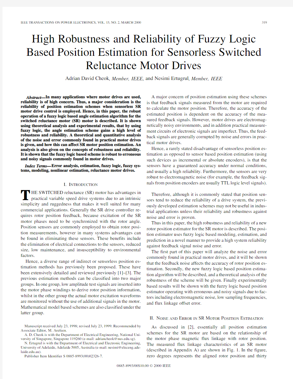
II.N OISE AND E RROR IN SR M OTOR P OSITION E STIMATION As discussed in[2],essentially all position estimation schemes for the SR motor are based on the relationship of the motor phase magnetic flux linkage with rotor position. The measured flux linkage characteristics of an SR motor (described in Appendix A)are shown in Fig.1.In the figure, zero degrees represents the aligned rotor position and thirty
0885-8993/00$10.00?2000IEEE
Fig.1.Measured magnetization characteristics of SR motor(as flux linkage varies from0to1,surface color changes from dark to light).
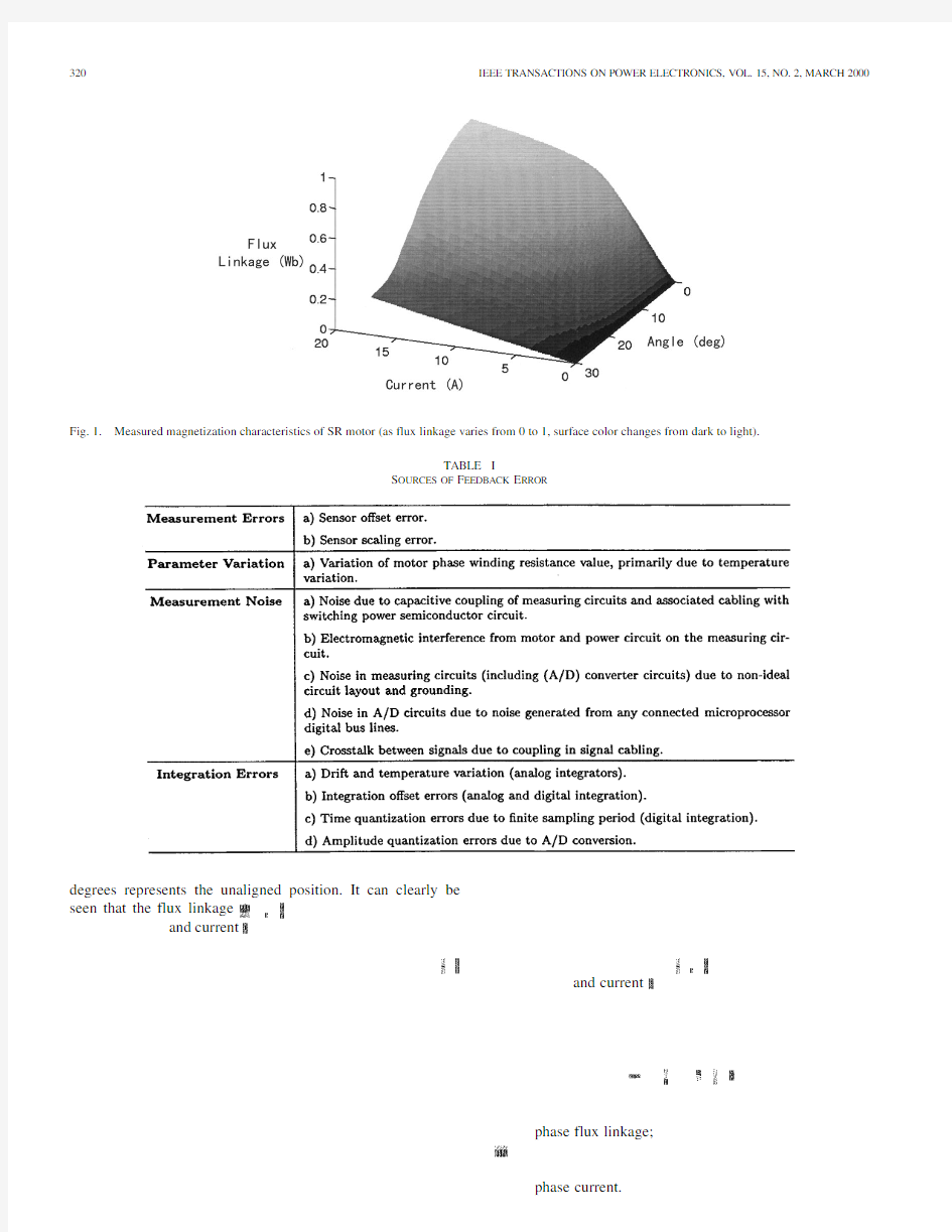
TABLE I
S OURCES OF F EEDBACK E RROR
degrees represents the unaligned position.It can clearly be
seen that the flux linkage
and current
and current
phase flux linkage;
phase current.
CHEOK AND ERTUGRUL:HIGH ROBUSTNESS AND RELIABILITY OF FUZZY LOGIC BASED POSITION ESTIMATION 321
TABLE II
A NALYTICAL E RROR E
XPRESSIONS
Fig.2.Flux linkage versus current curves for SR motor.
Analog integrators can be used to estimate the flux linkages of the motor but these often have the problem of drift in the output signal due to temperature sensitivity and the need for compensation [6].Therefore the integration may be performed digitally as shown in (2).This requires digitized phase voltage and current signals that are measured using analog to digital (A/D)
converters
(3)
where
(4)
(5)(6)
where
is
322IEEE TRANSACTIONS ON POWER ELECTRONICS,VOL.15,NO.2,MARCH
2000
Fig.3.(a)Rotor angle versus flux linkage and(b)angle error for10%flux linkage feedback error.
with physical value of voltage in the motor,
is the physical value of flux linkage in the motor.
The source of the feedback error components in practical motor drives can be classified under various groups,as shown in Table I.
Using these classifications,an expression for the total flux linkage error due to the various error producing sources can be found.The total flux linkage error at some
sample
CHEOK AND ERTUGRUL:HIGH ROBUSTNESS AND RELIABILITY OF FUZZY LOGIC BASED POSITION ESTIMATION 323
TABLE III
M INIMUM A NGLE E STIMATION E RROR A MPLITUDE FOR +10%E RROR IN F LUX
L INKAGE F EEDBACK V
ALUES
will be given
by
can be written
as
the angle error can be written
as
the angle error due to error in the current feed-back.
By examining again the contour curves of angle with respect to current and flux (Fig.2)it can be seen that similarly to the case of flux linkage error,the angle estimation error is most sensitive to current feedback error near the aligned and unaligned rotor positions and when the motor current is low.This results in the fact that in these areas the partial derivative of angle with respect to current will be high.
Generally there will be errors in both the flux linkage and current feedback.To consider the effect of simultaneous flux linkage and current errors on the position estimation the fol-lowing expression may be
employed
324IEEE TRANSACTIONS ON POWER ELECTRONICS,VOL.15,NO.2,MARCH2000
Fig.4.(a)Rotor angle versus current,(b)angle error for10%current feedback error.
These curves are derived from the motor magnetization charac-
teristics previously shown in Fig.1.
From the functions shown in Fig.3(a),the function
CHEOK AND ERTUGRUL:HIGH ROBUSTNESS AND RELIABILITY OF FUZZY LOGIC BASED POSITION ESTIMATION325 TABLE IV
M INIMUM A NGLE E STIMATION E RROR A MPLITUDE FOR+10%E RROR IN
C URRENT F EEDBACK V ALUES
Fig.5.The complete block diagram of the FL based position estimation
algorithm.
The minimum resultant error amplitude for a%error in
the flux linkage for each of the curves shown in Fig.3(a)is
shown in Table III.The results are shown in both absolute de-
grees,and as a percentage of an electrical cycle of30which
maps input values of flux linkage and current to output values
of position
326IEEE TRANSACTIONS ON POWER ELECTRONICS,VOL.15,NO.2,MARCH
2000
Fig.6.SR model fuzzy rule base (sm =small,med =medium,XX =no rule).HIghlighted cell is the fuzzy set shown in Fig.
7.
Fig.7.
Expanded subset of SR model fuzzy rule base.
In Fig.6results are shown of the generated fuzzy rule base
for the motor used in the research,after the rule base was trained with measured data.
The fuzzy rule based model is utilized during the operation of the position estimation scheme to calculate the rotor position from input measurements of current and estimated flux linkage.First,while the motor is running,the phase currents and volt-ages in each of the motor phases are measured,and the phase flux linkage is estimated by trapezoidal integration using the motor voltage (2).
After flux linkage estimation,the crisp (or numeric)flux linkage and measured current values of each motor phase are then fuzzified and input into the FL rule based SR motor model.Fuzzy rules in the rule base will be triggered by the crisp inputs,which will then generate a fuzzy set output rotor position.This is then defuzzified to produce a crisp value of estimated rotor
position.The hardware and software implementation details of the procedure can be examined in [9].A.Robustness of Fuzzy Model Based Method
To examine why there is robustness to noise and error in fuzzy rule based modeling,it should first be noted that each rule of the fuzzy rule base shown in Fig.6expresses heuristically the motor characteristics in each region using fuzzy reasoning.Each rule will have the
form
th
rule;
antecedent fuzzy set in the flux linkage fuzzy set do-main with membership
function
antecedent fuzzy set in the current fuzzy set domain
with membership
function
;,
variable domains represent a linguistic variable and are de-fined over a range of values or a region with membership value ranging from 0to 1.In this work the fuzzy sets were defined to be triangular with the maximum value at the center of the fuzzy set’s respective region.The two other vertices were chosen to lie at the centers of the two adjacent fuzzy regions,and at these two points the membership values are zero.
Hence for any given rule,both the antecedents and the conse-quents in the input–output domains will be defined for a given range of values.For example consider a rule from the motor model that was shown in Fig.
6
CHEOK AND ERTUGRUL:HIGH ROBUSTNESS AND RELIABILITY OF FUZZY LOGIC BASED POSITION ESTIMATION
327
Fig.8.Fuzzy variable domain sets:(a)flux linkage,(b)current,and (c)rotor position.Here ( ), (i ),and ( )are the membership values of the fuzzy sets in the flux,current,and angle domains,
respectively.
Fig.9.Waveforms for 0–1000rpm transient test:(a)phase voltage,(b)phase current,(c)actual position,and (d)estimated position.
the angle domain,and it is triggered by the antecedent fuzzy
sets
(medium)in the current domain.The width or size of the membership functions of the fuzzy sets can be considered as an allowable level of noise [10],[11].This means that an input data point with error or noise can still
328IEEE TRANSACTIONS ON POWER ELECTRONICS,VOL.15,NO.2,MARCH
2000
Fig.10.SR motor phase current:(a)without noise,(b)with added noise(10%of maximum),and(c)expanded comparison of current waveforms,with and without noise.
be placed in the same fuzzy set as the same input data with no error or noise.Thus by fuzzification of the input signals,input data which is corrupted by noise can be accepted in the same set as the same data without noise but with a different membership function[12].The length or range of the fuzzy set membership function will determine the range of values that will be accepted as part of the same set.The range can be defined such that small deviations in the input data do not have a significant effect on the output position estimation.
However,it should also be noted that a disadvantage of using the fuzzy rule based modeling is that an inverse relationship exists between robustness and resolution.As the robustness to input signal noise and error increases due to a widening of the fuzzy sets,the output resolution decreases due to the wider par-titioning of the input and output signal domains.Therefore a balance must be found between error robustness and output ac-curacy.In this research work each variable domain of flux,cur-rent,and angle was divided up into the fuzzy regions as shown in Fig.8.These resulted in a good compromise between accu-racy and robustness to noise and error.
However,as in all cases where finite width fuzzy sets are used,when there is zero or very small input signal error,the output will normally still contain some error or uncertainty due to the fuzzy set partitioning of the input and output domains. This entails that,strictly speaking,if robustness is not of concern then conventional schemes may result in higher accuracy at zero or no noise levels.
To observe the performance of the scheme with no feedback signal noise(and only a small error due to numerical integration of flux linkage),simulation results are shown in Fig.9.In the test the average value of error between actual and estimated angle
is
CHEOK AND ERTUGRUL:HIGH ROBUSTNESS AND RELIABILITY OF FUZZY LOGIC BASED POSITION ESTIMATION
329
Fig.11.SR motor phase voltage:(a)without noise,(b)with added noise (10%of maximum),and (c)expanded comparison of voltage waveforms,with and without
noise.
Fig.12.Ten percent noise:(a)measured rotor position and (b)estimated rotor position.
This error is mainly due to the above mentioned uncertainty of fuzzy partitioning.To increase the accuracy of the scheme at zero or low feedback error,the number of fuzzy regions may be increased or optimized,at the expense of robustness.The robustness of the scheme will be examined with experimental results in the following section.
330IEEE TRANSACTIONS ON POWER ELECTRONICS,VOL.15,NO.2,MARCH
2000
Fig.13.Twenty percent of maximum amplitude noise:(a)SR motor phase current,(b)expanded comparison of current waveforms,with and without noise,(c)
SR motor phase voltage,and(d)expanded comparison of voltage waveforms,with and without
noise.
Fig.14.Twenty percent noise:estimated angle.
IV.E XPERIMENTAL R OBUSTNESS T ESTS
To examine the experimental robustness of the angle estima-tion algorithm,it is firstly instructive to examine the concept of robustness from the field of robust statistics.Huber has defined robust algorithms as having the following features[13].
1)The algorithm should have a reasonably good accuracy in
the assumed model of the underlying system.
2)Small deviations of the data should decrease the perfor-
mance of the algorithm by only a small amount.
3)Large deviations in the data should not cause a catas-
trophe.
The first of these requirements essentially states that the output of the algorithm should be accurate when the input data is noise free.It was seen in[8],[9],and Fig.9that the accuracy of the algorithm in predicting rotor position has a good accuracy for relatively noise free feedback signals of current and voltage. Therefore,the sensorless position detection algorithm has been shown to satisfy the first requirement of a robust algorithm. To satisfy the second requirement of a robust system entails that small deviations in the inputs of the sensorless algorithm should not have a significant adverse effect on the output rotor position estimate.
Furthermore,to satisfy the third requirement of algorithm ro-bustness,the notion of a breakdown point should be considered [14].The breakdown point is defined as a point where the algo-rithm fails by producing an unacceptably high output error due to a large deviation in the input data.A deviation in the input data can be defined as large when it has abnormally high devia-tion from the correct value,compared to the mean level of input data noise.For example in the SR motor drive there may be high amplitude but short duration periods of electromagnetic noise, due to fast turn off of the current in the inverter power devices.
CHEOK AND ERTUGRUL:HIGH ROBUSTNESS AND RELIABILITY OF FUZZY LOGIC BASED POSITION ESTIMATION
331
Fig.15.(a)Current:6kHz sampling and(b)current:1.5kHz sampling.
In the field of robust statistics these higher deviations in the data are termed outliers,as opposed to inliers which lie closer to the mean level of noise[15].Although these robust statistic con-cepts are directly applicable to engineering tasks such as mod-eling and pattern recognition,the idea of a breakdown point and outlier and inlier data is applied in the FL based estimation al-gorithm by testing the algorithm with a very high level of signal noise,as detailed below.
A.Measurement Error Tests
In Figs.10and11the waveforms of current and voltage for one phase of the SR motor are shown for the case when the motor is operating in single pulse mode at a steady speed of 660rpm.There is an added random noise error with an am-plitude of10%of the maximum level of the measured signals. The added noise is Gaussian in nature,and therefore,has a finite variance,(the problem of non-Gaussian noise in this scheme has previously been examined in[7]).The expanded view of the cur-rent and voltage in Figs.10(c)and11(c)clearly shows that the voltage and current with noise deviates significantly at various points in time from the measured values without added noise. The measured and indirectly estimated rotor angle for this test is shown in Fig.12.The average amplitude of the error between the measured and estimated angle in this test
is
,)plane.As there are simultaneous errors in both the flux linkage and current feedback in this test,the total error will be a combination of the two errors as expressed in(11). Therefore,it can be seen that the use of fuzzy sets improves the robustness of position estimation,due to the fact that the av-erage position estimation error using the fuzzy model is of the same order as the minimum error using the nonfuzzy method, and the maximum error of the fuzzy method is significantly lower.
Further experiments were carried out to test the scheme at higher noise levels,and to see the operational limits of the cur-rent system.The level of noise imposed on the motor waveforms of current and voltage was increased to20%of the input mea-sured signals.It can be seen from Fig.13that in this set of results the noise has a significant component,and provides a difficult test for the sensorless algorithm.In Fig.14the estimated angle from the angle estimation algorithm is shown for this experi-ment(the measured angle was shown above in Fig.12).It can be seen that the general trajectory of the rotor angle has been re-tained in this test,even for this high level of noise.The average angle estimation error
is
332IEEE TRANSACTIONS ON POWER ELECTRONICS,VOL.15,NO.2,MARCH2000
https://www.doczj.com/doc/2e9011615.html,parison of flux linkages derived with6and1.5kHz sampling frequencies.
Furthermore,at no point in this test has the large deviation of the
input current and voltage data caused a catastrophic breakdown
of the algorithm,and thus the third requirement of a robust al-
gorithm has also been satisfied.
Hence,the requirements of a robust algorithm have been
demonstrated in this test.It has been shown that the large
deviations in the input current and voltage do not produce a
catastrophic breakdown in the algorithm,and even the peak
estimation error has a lower percentage error than the peak
input error.In addition,as the average angle estimation error
in this high noise test was
CHEOK AND ERTUGRUL:HIGH ROBUSTNESS AND RELIABILITY OF FUZZY LOGIC BASED POSITION ESTIMATION333
Fig.17.Sampling frequency at1.5kHz:(a)measured angle and(b)estimated
angle.
C.Flux Linkage Offset Error
As detailed above,the flux linkage of each motor phase is
estimated by integration using the measured phase voltages and
phase currents.In the SR motor,the flux always returns to zero
at the end of each current conduction period,which allows the
integrator to be reset in every electrical cycle.This prevents any
large accumulation of errors due to the effects of current and
voltage dc offset,measurement errors,and resistance variation.
For this reason,the flux estimation technique is very effective
in the SR motor.
Although the flux linkage integration is reset in each elec-
trical cycle,to test the robustness of the angle estimation algo-
rithm,results are shown below for operation with flux linkage
waveforms which have a constant offset error.
Fig.18(a)shows the flux linkage for the case when the motor
is operating in the chopping mode with a speed of162rpm.In
this test a flux linkage error is added such that the flux linkage
has a constant positive offset of0.025Vs,or4%of the peak
flux linkage value in this test.Although this is not an overly
large error value,due to the fact that is has a constant value,it
means that the relative error effect at the lower flux values is
higher than for the peak flux values.
The estimated rotor position for this test is shown together
with the actual angle in Fig.18(b)and(c).The average angle
estimation error in this test is
334IEEE TRANSACTIONS ON POWER ELECTRONICS,VOL.15,NO.2,MARCH2000
estimation scheme has a high level of robustness and reliability, and is thus well suited for a wide range of practical systems. Results were detailed which showed that the scheme could suc-cessfully and reliably operate under erroneous operating condi-tions that are commonly found in motor drive environments as follows.
1)Measurement errors due to noise.
2)Low bandwidth motor waveform measurements(e.g.,due
to slower analog to digital converters).
3)Flux linkage estimation errors,which may be caused by:
a)Offset errors.
b)Measurement errors.
c)Noise.
In order to compare the results of the fuzzy logic based method with nonfuzzy angle estimation,analytical expres-sions were given which described the effect of current and flux linkage input errors on the angle estimation accuracy of nonfuzzy schemes.Then the position estimation errors were calculated for nonfuzzy estimation.Hence,it was confirmed that the average and maximum position estimation errors of the fuzzy logic based estimation scheme due to feedback signal error,were low compared to the nonfuzzy estimation methods. The ability of the FL based method to cope with high levels of noise derives from the system’s ability of fuzzifying the input signals and then processing with fuzzy linguistic rules.With this system,an input with noise will normally be able to be partially a member of the same membership function that the error free signal would be.This is in fact a unique ability of fuzzy logic, as opposed to crisp logic.Therefore,the same rules can be trig-gered by noisy and noise free signals,depending on the level of the noise.Hence,using the benefits of fuzzy reasoning rotor position can be successfully and reliably estimated under high error and noise conditions in practical SR drives.
A PPENDIX A
E XPERIMENTAL M OTOR D ATA
Number of phases4
Number of rotor poles6
Number of stator poles8
Rated power4kW
Rated speed1500rpm
R EFERENCES
[1] A.D.Cheok and N.Ertugrul,“Sensorless rotor position detection tech-
niques in switched reluctance motor drives,”in Proc.Australasian Univ.
Power Eng.Conf.,1995,pp.84–89.
[2]W.F.Ray and I.H.Al-bahadly,“Sensorless methods for determining
the rotor position of switched reluctance motors,”in Proc.5th Eur.Conf.
Power Electron.Appl.,1993,pp.7–13.
[3]P.Acarnley,E.D.French,and I.H.Al-bahadly,“Position estimation
in switched reluctance drives,”in Proc.7th Eur.Conf.Power Electron.
Applicat.,vol.3,1995,pp.765–770.
[4]I.Husain and M.Ehsani,“Error analysis in indirect rotor position
sensing of switched reluctance motors,”IEEE Trans.Ind.Electron., vol.41,pp.301–307,June1994.
[5]S.Rehman and D.G.Taylor,“Issues in position estimation of sr motors,”
in IEEE Power Electron.Spec.Conf.Rec.,1996,pp.337–343.
[6]T.Williams and R.Carter,“Measurement of machine inductances using
an operational amplifier integrator,”https://www.doczj.com/doc/2e9011615.html,c.,vol.10,pp.
177–181,1972/73.
[7] A.D.Cheok and N.Ertugrul,“High robustness and reliability of a fuzzy
logic based angle estimation algorithm for practical switched reluctance motor drives,”in Proc.IEEE Power Electron.Specialists Conf.Rec., 1998,pp.1302–1308.
[8],“A model free fuzzy logic based rotor position sensorless switched
reluctance motor drive,”in Proc.IEEE Ind.Appl.Soc.Annu.Meeting, 1996,pp.76–83.
[9]N.Ertugrul and A.D.Cheok,“Indirect angle estimation in switched
reluctance motor drives using fuzzy logic based predictor/corrector,”in Proc.IEEE Power Electron.Spec.Conf.Rec.,1998,pp.845–851. [10]P.J.Costa Branco and J.A.Dente,“An experiment in automatic mod-
eling an electrical drive system using fuzzy logic,”IEEE Trans.Syst., Man,Cybern.C,vol.28,pp.254–262,May1998.
[11]G.C.Mouzouris and J.M.Mendel,“Dynamic non-singleton fuzzy logic
systems for nonlinear modeling,”IEEE Trans.Fuzzy Syst.,vol.5,pp.
199–208,May1997.
[12]J.van den Berg and D.Ettes,“Representation and learning capabilities
of additive fuzzy systems,”in Proc.1998IEEE Int.Conf.Intell.Eng.
Syst.,1998,pp.121–126.
[13]P.J.Huber,Robust Statistics.New York:Wiley,1981.
[14]R.N.Dave and R.Krishnapuram,“Robust clustering methods:A unified
view,”IEEE Trans.Fuzzy Syst.,vol.5,no.2,pp.270–293,1997. [15] F.R.Hampel,E.M.Ponchotti,P.J.Rowsseuw,and W.A.Stahel,Robust
Statistics:The Approach Based on Influence Functions.New York: Wiley,1986.
[16] A.V.Radun,C.A.Ferreira,and E.Richter,“Two-channel switched re-
luctance starter/generator results,”IEEE Trans.Ind.Applicat.,vol.34, no.5,pp.1026–1034,Sept./Oct.
1998.
Adrian David Cheok(M’92)received the B.Eng.
(first class honors)and Ph.D.degrees from the Uni-
versity of Adelaide,Australia,in1993and1998,re-
spectively.
From1996to1998,he was with the Transmis-
sion and Distribution Department,Transportation
Systems Center,Mitsubishi Electric Corporation,
Amagasaki,Japan.Since1998,he has been an
Assistant Professor in the Department of Electrical
Engineering,National University of Singapore.His
research interests include power electronics and motor drives,fuzzy logic and soft computing,nonlinear modeling and control, noise and EMI,and digital signal processing.
Dr.Cheok is a Member of the IEEE Industrial Electronics Society and the IEEE Systems,Man,and Cybernetics
Society.
Nesimi Ertugrul(M’95)received the B.Sc.degree
in electrical engineering and the M.Sc.degree in
electronic and communication engineering,both
from the Istanbul Technical University,Istanbul,
Turkey,in1985and1989,respectively,and the
Ph.D.degree from the University of Newcastle upon
Tyne,U.K.,in1993.
He joined the University of Adelaide in1994.His
research interests include rotor position sensorless
operation of brushless permanent magnet and
switched reluctance motors,real-time control of electrical machine drives,electric vehicles,and power electronics utility systems.He is currently engaging in research in the field of interactive computer-based teaching and learning systems involving object-oriented programming and data acquisition.
Dr.Ertugrul is a Member of the IEEE Power Electronics Society and the IEEE Industry Applications Society.