CM3623
I C Proximity Sensor with Ambient Light Sensor and Interrupt
Rev: 0.995 Revised 27th-Jan-2010
2
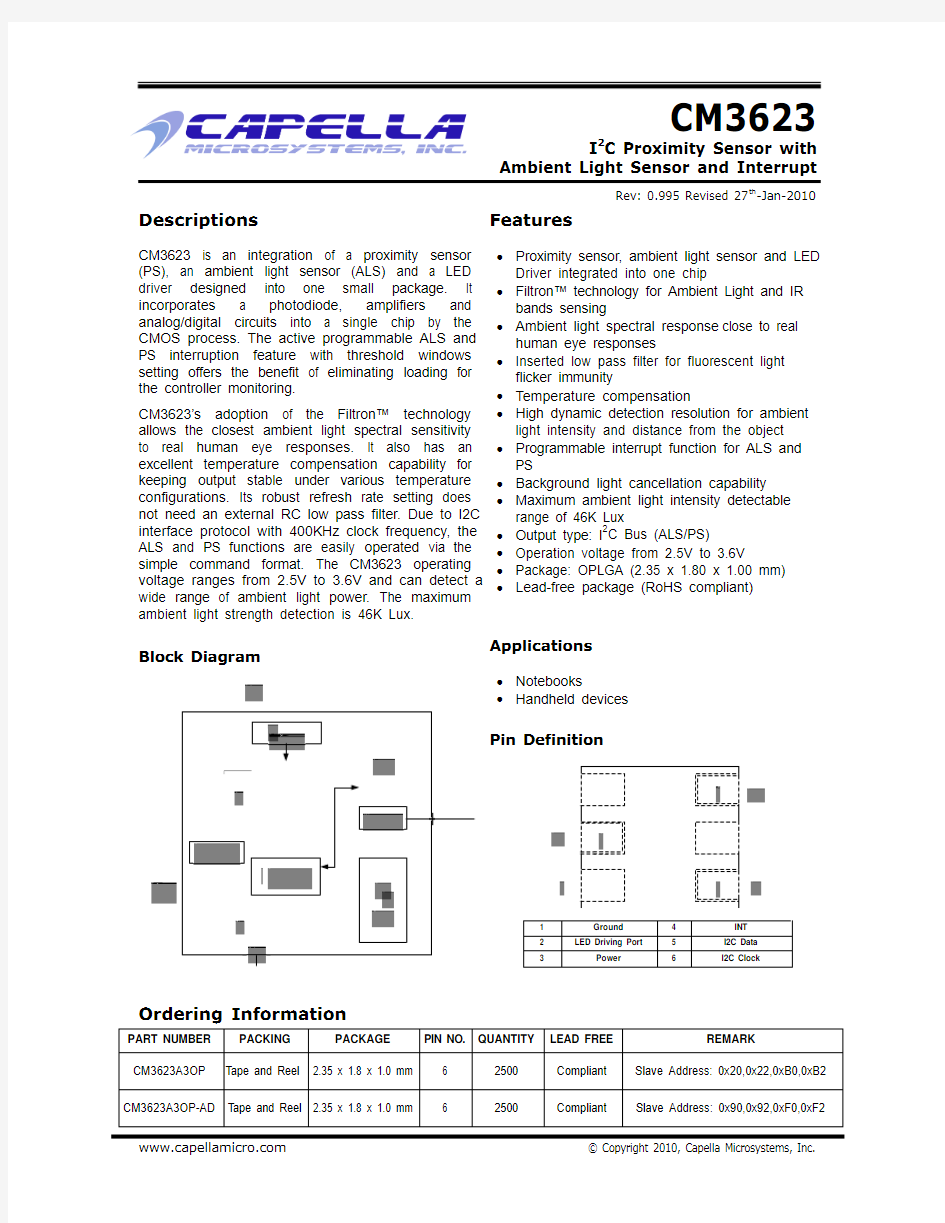
Descriptions
CM3623 is an integration of a proximity sensor (PS), an ambient light sensor (ALS) and a LED driver designed into one small package. It incorporates a photodiode, amplifiers and analog/digital circuits into a single chip by the CMOS process. The active programmable ALS and PS interruption feature with threshold windows setting offers the benefit of eliminating loading for the controller monitoring. CM3623’s adoption of the Filtron? technology allows the closest ambient light spectral sensitivity to real human eye responses. It also has an excellent temperature compensation capability for keeping output stable under various temperature configurations. Its robust refresh rate setting does not need an external RC low pass filter. Due to I2C interface protocol with 400KHz clock frequency, the ALS and PS functions are easily operated via the simple command format. The CM3623 operating voltage ranges from 2.5V to 3.6V and can detect a wide range of ambient light power. The maximum ambient light strength detection is 46K Lux.
Features
? Proximity sensor, ambient light sensor and LED Driver integrated into one chip ? Filtron? technology for Ambient Light and IR bands sensing ? Ambient light spectral response close to real human eye responses ? Inserted low pass filter for fluorescent light flicker immunity ? Temperature compensation ? High dynamic detection resolution for ambient light intensity and distance from the object ? Programmable interrupt function for ALS and PS ? Background light cancellation capability ? Maximum ambient light intensity detectable range of 46K Lux 2 ? Output type: I C Bus (ALS/PS) ? Operation voltage from 2.5V to 3.6V ? Package: OPLGA (2.35 x 1.80 x 1.00 mm) ? Lead-free package (RoHS compliant)
Block Diagram
Applications
? Notebooks ? Handheld devices
Pin Definition
Ordering Information
PART NUMBER CM3623A3OP PACKING PACKAGE PIN NO. QUANTITY 6 6 2500 2500 LEAD FREE Compliant Compliant REMARK Slave Address: 0x20,0x22,0xB0,0xB2 Slave Address: 0x90,0x92,0xF0,0xF2
Tape and Reel 2.35 x 1.8 x 1.0 mm
CM3623A3OP-AD Tape and Reel 2.35 x 1.8 x 1.0 mm
https://www.doczj.com/doc/212512264.html,
? Copyright 2010, Capella Microsystems, Inc.
CM3623
Proximity Sensor with ALS and Interrupt
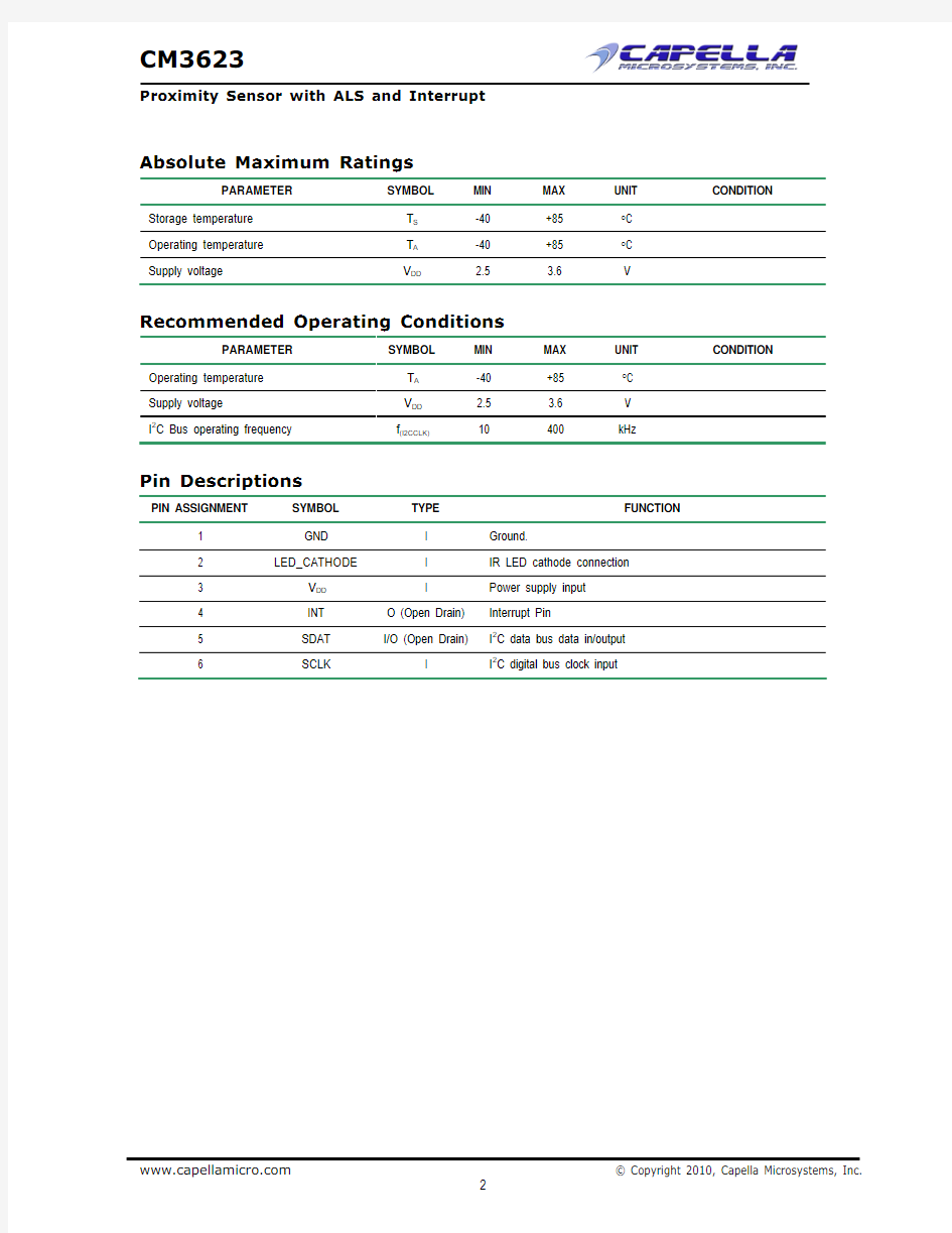
Absolute Maximum Ratings
PARAMETER Storage temperature Operating temperature Supply voltage SYMBOL TS TA VDD MIN -40 -40 2.5 MAX +85 +85 3.6 UNIT °C °C V CONDITION
Recommended Operating Conditions
PARAMETER Operating temperature Supply voltage I C Bus operating frequency
2
SYMBOL TA VDD f(I2CCLK)
MIN -40 2.5 10
MAX +85 3.6 400
UNIT °C V kHz
CONDITION
Pin Descriptions
PIN ASSIGNMENT 1 2 3 4 5 6 SYMBOL GND LED_CATHODE VDD INT SDAT SCLK TYPE I I I O (Open Drain) I/O (Open Drain) I Ground. IR LED cathode connection Power supply input Interrupt Pin I2C data bus data in/output I2C digital bus clock input FUNCTION
https://www.doczj.com/doc/212512264.html,
? Copyright 2010, Capella Microsystems, Inc.
2
CM3623
Proximity Sensor with ALS and Interrupt
Electrical & Optical Specifications
PARAMETER Supply voltage Supply current I2C supply voltage Logic High I2C signal input Logic Low Logic High I2C signal input Logic Low Peak sensitivity wavelength of ALS Peak sensitivity wavelength of PS Minimum Detectable intensity Maximum Dark offset Operating temperature Shutdown current Note: 1. Test condition: VDD = 3.3V, Temperature: 25°C. 2. Light source: White LED. 3. Maximum detection range to ambient light can be determined by ALS refresh time adjustment. Refer to Figure 6, Page 6. TA IDD (SD) 0 -40 800 45875 1 +85 STEP °C nA Light Condition = Dark; VDD= 3.6 V, Ta= 25°C VIL λP λPPS 0.7 550 850 0.0875 Lux nm nm IT = 800ms, Word Mode, Note1, 2, 3 IT = 100ms, Word Mode, Note1, 2, 3 IT = 100ms, Note 1,2 VIL VIH 0.8 1.1 V Note1, VPULL UP = 1.8V SYMBOL VDD IDD VPULL UP VIH MIN 2.5 130 1.8 - 3.3 1.5 V Note1, VPULL UP = 3.3V Note1, VPULL UP = 1.8V TYP MAX 3.6 UNIT V uA V Note1, VPULL UP = 3.3V Excluded LED driving CONDITION
https://www.doczj.com/doc/212512264.html,
? Copyright 2010, Capella Microsystems, Inc.
3
CM3623
Proximity Sensor with ALS and Interrupt
I2C Bus Timing Characteristics
PARAMETER SYMBOL STANDARD MODE MIN Clock frequency Bus free time between start and stop condition Hold time after (repeated) start condition. After this period, the first clock is generated Repeated start condition setup time Stop condition setup time Data hold time Data setup time I C clock (SCK) low period I C clock (SCK) high period Detect clock/data low timeout Clock / Data fall time Clock / Data rise time
2 2
FAST MODE MIN 10 1.3 0.6 0.6 0.6 MAX 400
UNIT
MAX 100
f(SMBCLK) t(BUF) t(HDSTA) t(SUSTA) t(SUSTO) t(HDDAT) t(SUDAT) t(LOW) t(HIGH) t(TIMEOUT) t(F) t(R)
10 4.7 4.0 4.7 4.0
kHz us us us us
300 250 4.7 4.0 25 35 300 1000 100 1.3 0.6 ---
90
ns ns us us
--300 300
ms ns ns
{
{
{
Figure 1. I C Bus Timing Diagram
2
https://www.doczj.com/doc/212512264.html,
? Copyright 2010, Capella Microsystems, Inc.
4
{
CM3623
Proximity Sensor with ALS and Interrupt
Parameter Timing Information
Figure 2. I2C Bus Timing for Send Byte Command Format
Figure 3. I2C Bus Timing for Receive Byte Command Format
https://www.doczj.com/doc/212512264.html,
? Copyright 2010, Capella Microsystems, Inc.
5
CM3623
Proximity Sensor with ALS and Interrupt
Typical Performance Characteristics
CM3623 ALS & PS Sensor Spectral Response
CM3623 View Angle OPLGA package
1.1 1 0.9 N o r m a liz e d O u tp u t 0.8 0.7 0.6 0.5 0.4 0.3 0.2 0.1 CM3623 ALS Ideal Cosine
100% 90% 80%
Relative response (%)
70% 60% 50% 40% 30% 20% 10% 0% 400 450 500 550 600 650 700 750 800 850 900 950 1000
0 0 10 20 30 40 50 60 70 80 -9 0 -8 0 -7 0 -6 0 -5 0 -4 0 -3 0 -2 0 -1 0 View Angle 90
Wavelength (nm)
CM3623 PS Sensor
CM3623 ALS Sensor
Figure 4. Normalized Spectral Response
ALS IT vs. Max. Detection Range (WORD Mode)
70000 60000 50000
Figure 5. ALS Normalized Output vs View Angle
Temperature vs IDD
150 140 130 IDD(uA) 120 110 100 90
S te p
40000 30000 20000 10000 0 0 5000 10000 15000 20000 25000 Lux 100ms 200ms 400ms 800ms 30000 35000 40000 45000 50000 55000
80 -40 -30 -20 -10 0 10 20 30 40 50 60 70 80 90 100 Temperature ℃
Figure 6. ALS Refresh Time vs Max Detect Range
Figure 7. IDD vs. Temperature
https://www.doczj.com/doc/212512264.html,
? Copyright 2010, Capella Microsystems, Inc.
6
CM3623
Proximity Sensor with ALS and Interrupt
Application Information
Pin Connection with the Host
CM3623 is a cost effective solution for a proximity sensor with I C interface. The standard serial digital interface easily accesses “light intensity” without using complex calculations and programming by an external controller. Two additional capacitors in the circuit can be used for the following purposes: (1) the 0.1uF capacitor near the VDD pin is used for power supply noise rejection and (2) the 2.2uF capacitor, which connects parallel to the RLED, is used to prevent the IRLED voltage from instantly dropping when the IRLED is turned on.
2
Figure 8. Hardware Pin Connection Diagram
Digital interface
CM3623 contains an 8-bit command register written via the I C bus. All operations can be controlled by the command register. The simple command structure enables the user to easily program the operation setting and latch the light data from CM3623. The CM3623 I2C command format description for Read and Write operations between CM3623 and the host is shown in Figure 9. The white sections indicate host activity and the gray sections indicate CM3623’s acknowledgement of the host access activity.
2
Figure 9. Send byte/Receive byte protocol
https://www.doczj.com/doc/212512264.html,
? Copyright 2010, Capella Microsystems, Inc.
7
CM3623
Proximity Sensor with ALS and Interrupt
Slave Address and Function Description
As shown in the Table 1, CM3623 has two different ordering part numbers for different Slave Address individually. For ease to describe the function of CM3623, we would take CM3623A3OP as the example here. If customer would like to use CM3623A3OP-AD, the Slave Address has to be replaced as Table 1 addressed accordingly. CM3623 has two fixed and separate slave address groups for ALS and PS. For Write command setting, the slave address uses 0X20 (ALS) and 0XB0/0XB2 (PS); for Read command setting, the host uses addresses 0X21, 0X23 (ALS) and 0XB1 (PS) to latch the data independently. CM3623 has 16-bit resolution and provides two kinds of ALS data modes for the host application. For Byte mode reading, the host can read the data from the 0X21 address. For Word mode reading, the host first reads the data from the 0X23 address and then reads the 0X21 address data to complete the Word mode data collection. For PS data reading, the host can read the data from the 0XB1 address. Descriptions for each slave address operation are shown in Table 1.
SLAVE ADDRESS Ordering Part Number ALS CM3623A3OP 0x20 0x21 0x23 PS Initialization Address 0xB0/0xB2 0xB1 0x22 CM3623A3OP-AD 0x90 0x91 0x93 0xF0/0xF2 0xF1 0x92 OPERATION Write Command to CM3623 Read MSB 8 bits of CM3623 ambient light data Read LSB 8 bits of CM3623 ambient light data Write Command to CM3623 Read 8 bits of CM3623 proximity data CM3623 initialization usage
Table 1. Slave Address and Read/Write Function Selection Format
Command Register Format
CM3623 provides the 8-bits command register for ALS and PS controlling independently. The following tables are the description of the command format. Table 2 and 3 are ALS function, and Table 4 and 5 are PS function. Ambient Light Sensor Command
ALS COMMAND FORMAT (0X20) GAIN_ALS BIT 7 GAIN1 BIT 6 GAIN0 THD_ALS BIT 5 THD1_ALS BIT 4 THD0_ALS BIT 3 IT1_ALS IT_ALS BIT 2 IT0_ALS WDM BIT 1 WDM SD_ALS BIT 0 SD_ALS
DESCRIPTION GAIN_ALS THD_ALS IT_ALS WDM SD_ALS ALS Gain setting for Sensitivity Range Selection. ALS Threshold Window Setting. ALS Integration Time Setting. ALS Data Mode Setting ALS Shutdown Mode Setting.
Table 2. ALS Command Register Bits Description
BITS SETTING GAIN_ALS (GAIN1 : GAIN0) THD_ALS Refer to Table 6 (THD1_ALS: THD0_ALS) SD_ALS DESCRIPTION (0 : 0) = (÷ 1) (0 : 1) = (÷ 2) (1 : 0) = (÷ 4) (1 : 1) = (÷ 8) BITS SETTING IT_ALS (IT1_ALS : IT0_ALS) WDM DESCRIPTION (0 : 0) = 100 ms (0 : 1) = 200 ms (1 : 0) = 400 ms (1 : 1) = 800 ms 0 = BYTE Mode 1 = WORD Mode 0 = ALS SD Disable 1 = ALS SD Enable
Table 3. ALS Register Table Setting https://www.doczj.com/doc/212512264.html,
? Copyright 2010, Capella Microsystems, Inc.
8
CM3623
Proximity Sensor with ALS and Interrupt
Proximity Sensor Command
PS COMMAND FORMAT (0XB0) DR_PS BIT 7 DR1_PS BIT 6 DR0_PS BIT 5 IT1_PS IT_PS BIT 4 IT0_PS INT_ALS BIT 3 INT_ALS INT_PS BIT 2 INT_PS Res. BIT 1 0 SD_PS BIT 0 SD_PS
DESCRIPTION DR_PS IT_PS INT_ALS INT_PS SD_PS IR LED On/Off Duty Ratio Setting PS Integration Time Setting ALS Interruption Setting PS Interruption Setting PS Shutdown Mode Setting
Table 4. PS Command Register Bits Description
BITS SETTING DR_PS (DR1_PS : DR0_PS) DESCRIPTION (0 : 0) = 1/160 (0 : 1) = 1/320 (1 : 0) = 1/640 (1 : 1) = 1/1280 (0 : 0) = 1T IT_PS (IT1_PS: IT0_PS) (0 : 1) = 1.1875T (1 : 0) = 1.4375T (1 : 1) = 1.875T BITS SETTING INT_ALS INT_PS SD_PS DESCRIPTION 0 = ALS INT Disable 1 = ALS INT Enable 0 = PS INT Disable 1 = PS INT Enable 0 = PS SD Disable 1 = PS SD Enable
Table 5. PS Register Table Setting Adjustable Sampling Time CM3623 embedded LED driver that can drives the external IR LED with “LED CATHODE” pin. It drives IR LED 2 by pulsed duty cycle. The IR LED On/Off duty ratio can be programmable by I C command of bit 7/6 in 0X20 address. It will be related to the current consumption during CM3623 operation.
Initialization
CM3623 needs to be initialized while the system’s power is on. The initialization includes two major steps: (1). Check “INT” pin state. If the state is “Low”, clear Interrupt of ALS and/or PS, till INT pin state is High” (2). Write the initial value, 10 (HEX) or 20(HEX) into the 0X22 address. 10(HEX) represents the normal operation which include INT function. (See Figure 8 for HW diagram). 20(HEX) represents simple PS Logic High/Low mode (page 15). If customer select PS Logic High/Low mode, the INT_ALS (BIT 3) and INT_PS (BIT 2) in 0xB0 have to be disabled. After the initialization is completed, CM3623 can be programmable for operation by Write command setting from the host. The CM3623 initialization is recommended to be completed within 150ms. A flow chart, which shows the description of the initialization in the software program rule, is shown in Figure 10.
Figure 10. CM3623 Initialization Description
https://www.doczj.com/doc/212512264.html,
? Copyright 2010, Capella Microsystems, Inc.
9
CM3623
Proximity Sensor with ALS and Interrupt
Threshold Window Setting
ALS Threshold Window Setting The threshold window in CM3623 can be dynamically programmed by the register setting via Write command. Two registers, GAIN_ALS and THD_ALS, cooperate with this application. They easily define the threshold range by multiplying the value of the resolution (LUX/STEP) by the threshold level. Table 6 is the description about the threshold windows width (Step) for reading light data with Byte mode and Word mode.
GAIN_ALS GAIN1 GAIN0 THD_ALS THD1_ALS THD0_ALS THRESHOLD WINDOW (STEP) BYTE MODE WORD MODE ± 256 ± 512 ± 1024 ± 2048 ± 128 ± 256 ± 512 ± 1024 ± 64 ± 128 ± 256 ± 512 ± 32 ± 64 ± 128 ± 256
0 0 1 1 0 0 1 1 0 0 1 1 0 0 1 1
0 1 0 1 0 1 0 1 0 1 0 1 0 1 0 1
0
0
±1
0
1
±2
1
0
±4
1
1
±8
Table 6. Threshold Window Setting for Byte / Word Mode Data Reading Here is an example for the application for IT = 100ms condition. With adding the light intensity resolution, it would be easy to calculate the threshold window in “Lux” unit. Table 7-1 is for Byte mode, and Table 7-2 is for Word mode condition.
GAIN_ALS GAIN1 GAIN0 RESOLUTION (LUX / STEP) (1) THD_ALS THD1_ALS 0 0 0 180 0 1 1 0 0 1 90 0 1 1 0 1 0 45 0 1 1 0 1 1 22.5 0 1 1 THD0_ALS 0 1 0 1 0 1 0 1 0 1 0 1 0 1 0 1 THRESHOLD (STEP) (2) ±1 ±2 ±4 ±8 ±1 ±2 ±4 ±8 ±1 ±2 ±4 ±8 ±1 ±2 ±4 ±8 THRESHOLD RANGE (LUX) (1) X (2) ± 180 ± 360 ± 720 ± 1440 ± 90 ± 180 ± 360 ± 720 ± 45 ± 90 ± 180 ± 360 ± 22.5 ± 45 ± 90 ± 180
Table 7-1. Byte Mode Threshold Setting/Range Table (WDM = 0)
https://www.doczj.com/doc/212512264.html,
? Copyright 2010, Capella Microsystems, Inc.
10
CM3623
Proximity Sensor with ALS and Interrupt
GAIN_ALS GAIN1 GAIN0
RESOLUTION (LUX / STEP) (1)
THD_ALS THD1_ALS 0 THD0_ALS 0 1 0 1 0 1 0 1 0 1 0 1 0 1 0 1
THRESHOLD (STEP) (2) ± 256 ± 512 ± 1024 ± 2048 ± 128 ± 256 ± 512 ± 1024 ± 64 ± 128 ± 256 ± 512 ± 32 ± 64 ± 128 ± 256
THRESHOLD RANGE (LUX) (1) X (2) ± 180 ± 360 ± 720 ± 1440 ± 90 ± 180 ± 360 ± 720 ± 45 ± 90 ± 180 ± 360 ± 22.5 ± 45 ± 90 ± 180
0
0
0 1 1 0 0 1 0.7 1 0 0 1 1 0 0 1 1
0
1
1
0
1
1
Table 7-2. Word Mode Threshold Setting/Range (WDM = 1) Programmable PS Threshold CM3623 provides a flexible way for determined the threshold window for PS interruption activity. The 8-bits 2 register in 0XB2 address are for the programming. Following I C specification definition, the interrupt signal is activated when the PS data is crossing over the threshold value. The minimum threshold value should be set 3 (0000, 0011) and the maximum value is 255 (1111, 1111). Table 6 is a description for the functionality The 1st PS threshold value should be completed before the 1st PS command setting by the host. After that, PS threshold can be changed by the application requirement anytime.
PS INT THRESHOULD COMMAND FORMAT (0XB2) BIT 7 THD7 BIT 6 THD6 BIT 5 THD5 BIT 4 THD4 BIT 3 THD3 BIT 2 THD2 BIT 1 THD1 BIT 0 THD0
DESCRIPTION 1. The threshold value range is from THD=3 (0000,0011) to THD=255 (1111,1111)
Table 8. Programmable PS THD Setting
https://www.doczj.com/doc/212512264.html,
? Copyright 2010, Capella Microsystems, Inc.
11
CM3623
Proximity Sensor with ALS and Interrupt
Data Access
CM3623 has 16-bit resolution for giving a high resolution to light intensity sensing. Because of the high resolution capability, CM3623 provides 2 kinds of ALS data mode for system application. Data mode selection can be determined by WDM bit. Gain setting bits are only used in Byte mode operation for changing the resolution of output step to light intensity. The maximum detection range equals the total steps of data mode multiplied by the resolution (Lux / Step). Table 9-1, 9-2, Figure 11-1 and 11-2 are examples of the descriptions of application setting.
WDM = 0 GAIN SET 0 0 1 1 0 1 0 1 1. Example condition: (a). IT = 100ms Note 2. WDM = 0 (Byte mode); Slave address for data read: 0X21 3. Based on Gain register setting, the host can latch the 8 bits data from CM3623 16 bits data buffer. As the gray area showing.
15 14 13 12 11
CM3623 16-BIT DATA BUFFER
10 9 8 7 6 5 4 3 2 1 0
RESOLUTION (LUX/STEP)
MAX DETECT RANGE (LUX) 45875 22938 11469 5735
180 90 45 22.5
Table 9-1. Byte Mode Data Access
WDM = 1 GAIN SET
Sequence 15 14 13 12 11
CM3623 16-BIT DATA BUFFER
RESOLUTION (LUX/STEP)
10 9 8 7 6 5 4 3 2 1 0
MAX DETECT RANGE (LUX)
1 0.7
Sequence
45875
2 1. Example condition: (a). IT = 100ms 2. WDM = 1 (Word mode); Slave address for data read: 0X21 and 0X23 3. For Word mode reading, Gain register setting value will be ignored on this application. 4. Data reading sequence for the host: (1). Set Read command to 0X23, read LSB 8 bits of 16 bits light data. (Sequence 1) (2). Set Read command to 0X21, read MSB 8 bits of 16 bits light data for completing Word mode data structure. (Sequence 2)
Note
Table 9-2. Word Mode Data Access
ALS Output Brightness Response Curve (IT = 100ms, WORD Mode)
70000 60000 50000
ALS Output Brightness Response Curve (IT = 100ms, BYTE Mode)
300 250 200
S te p
40000
S te p
0 5000 10000 15000 20000 25000 Lux 30000 35000 40000 45000 50000 55000
150 100 50 0 0 5000 10000 15000 20000 25000 Lux Gain 00 Gain 01 Gain 10 Gain 11 30000 35000 40000 45000 50000 55000
30000 20000 10000 0
Figure 11-1. ALS Output Brightness Response (Word Mode, IT = 100ms)
Figure 11-2. ALS Output Brightness Response (Byte Mode, IT = 100ms)
https://www.doczj.com/doc/212512264.html,
? Copyright 2010, Capella Microsystems, Inc.
12
CM3623
Proximity Sensor with ALS and Interrupt
Resolution to Ambient Light and Maximum Detection Range
CM3623 has four fixed integration time settings and resolutions for ambient light detection. To cooperate with the command register setting, such as GAIN_ALS, IT_ALS, and WDM, CM3623 provides flexible settings to determine the maximum detection range as an application requirement. Descriptions of the resolution and the maximum range for Word and Byte mode are shown in Tables 10 and 11.
COMMAND SET WDM GAIN_ALS (0 : 0) WDM = 0 (0 : 1) (1 : 0) (1 : 1) WDM = 1 (X : X) IT_ALS = 100 ms 180 90 45 22.5 0.7 RESOLUTION (LUX/STEP) IT_ALS = 200 ms 90 45 22.5 11.25 0.35 IT_ALS = 400 ms 45 22.5 11.25 5.6 0.175 IT_ALS = 800 ms 22.5 11.25 5.6 2.8 0.0875
Table 10. Resolution for Word /Byte Mode
COMMAND SET WDM GAIN_ALS (0 : 0) WDM = 0 (0 : 1) (1 : 0) (1 : 1) WDM = 1 (X : X) IT_ALS = 100 ms 45875 22938 11469 5735 45875 MAXIMUM DETECT RANGE (LUX) IT_ALS = 200 ms 22938 11469 5735 2868 22938 IT_ALS = 400 ms 11469 5735 2868 1434 11469 IT_ALS = 800 ms 5735 2868 1434 717 5735
Table 11. Maximum Detect Range for Word /Byte Mode
Distance Measurement for Proximity
CM3623 provides high precision measurements for the distance between the object and the sensor. The 256 steps deviation of the PS Code can precisely take measurements as the object gets closer to CM3623. The 2 relationship between the CM3623 detected object distance and the PS Code read out from the I C interface is shown in Figure 12. Once the furthest distance of the object has been confirmed, the continuous distance of each PS Code description can be traced along the curve trend.
CM3623 PS Code Vs Distance (100% White & 26% Gray level)
260 240 220 200 PS codes 180 160 140 120 100 80 60 40 20 0 102 12 17 22 27 32 37 42 47 52 57 62 67 72 77 82 87 92 97 2 7
Distance (mm) 100% White 26% Gray
Figure 12. Example of the Object Distance Measurement
https://www.doczj.com/doc/212512264.html,
? Copyright 2010, Capella Microsystems, Inc.
13
CM3623
Proximity Sensor with ALS and Interrupt
Interruption (INT)
CM3623 has an ALS and PS interrupt feature and emits as a single pin “INT”. The purpose of the interrupt feature is to actively inform the host once the sensed data level goes beyond the threshold setting. CM3623 compares the last two sets of data and if the difference is larger than the threshold value, the interrupt is asserted. There are two methods for driving an INT condition and Read/Write commands to CM3623: (1) If the host implements the INT function, it performs a modified Received Byte operation to disengage the CM3623 INT signal and acknowledges Alert Response Address (ARA), 0x18 (Hex). A command format for responding to an ARA is shown in Figure 13.
Figure 13. Command format for Responds to an ARA (2) If the host does not implement this feature, it should periodically access the ARA or read ARA before setting each read/write command. CM3623 INT and the command register need to specify when power-on state occurs (power goes from 0 to VDD), and as a result, the host may receive a non-meaningful INT interrupt signal. For wake up condition (from shutdown mode), in order to get the reference level, CM3623 does not activate the INT function after the initial 3-light data conversion. The fourth data value is used to compare it with the third data value. If the difference is larger than the threshold value, the interrupt is asserted by the INT pin. In the mean time, CM3623 continues sensing the light and makes the data conversion. When the host is free to read the data from CM3623, the host gets the most updated data for application usage. The other condition of INT activity is CM3623’s ambient light data overflow. When an overflow condition occurs (light intensity becomes strong and makes CM3623 output overflow), CM3623 asserts a one time interrupt to the host. CM3623 does not assert another interrupt signal until the light intensity comes out of overflow condition. For example: The threshold is set at 64 Lux and overflow is set at 300 Lux. When light is brighter than 300Lux, CM3623 only asserts an interrupt to the host the first time. When the light returns and is dimmer than 236 Lux (300 – 64 = 236), CM3623 asserts another interrupt to the host for updating. CM3623 provides two register bits for independently setting the ALS and PS interrupt function, which is easily operated via the command setting. Once the function has been disabled, the threshold setting is ignored. The host should read the data to adjust the next action periodically. When ALS and PS activate interrupt at the same time, the ALS wins communication via standard arbitration during the transfer of the two slave addresses; this is because its lowest address has top priority. After acknowledging the ALS address, the host receives the INT signal from CM3623 and reads the ARA again to execute the PS interrupt request. CM3623 is flexible in dealing with receiving the message when the two interrupts activate at the same time. The description of the sequence is shown in Figure 14. Sequence 1:
Sequence 2:
Figure 14. Interrupt acknowledge and data receive sequence Under normal operation, CM3623 always asserts the interrupt signal to the host when the difference of two instant lighting data between two refresh time settings is larger than the threshold setting.
https://www.doczj.com/doc/212512264.html,
? Copyright 2010, Capella Microsystems, Inc.
14
CM3623
Proximity Sensor with ALS and Interrupt
Proximity Sensor Logic High/Low mode
For systems without implementing the ALS and PS interrupt features, the Host\BB is able to do periodically data polling to get ALS output information via I2C interface. For Proximity sensing function, CM3623 provide with a simple PS Logic Hi/Low mode with logic high/low level output by INT pin. To apply this mode, it is necessary to write command ‘20(HEX)’ in 0x22 and INT_ALS (BIT 3) and INT_PS (BIT 2) of 0xB0 have to be disabled. When there is no object in the close proximity, the INT pin output level is logic “High”. When there is an object in the proximity detection range, the INT pin output level is logic “Low”. When the object moving away to out of proximity detection range, the INT pin output level is changed to logic “High”. In the PS “Hi/Low” mode, Host can decide to switch off panel when the INT logic level change from hi to low or switch on panel when the INT level changed from low to high. The PS detection threshold value is set by PS THD 8-bit register (See table 8). The PS THD setting range is from 3 to 255. If an object is approaching to the PS sensor, the INT pin voltage goes “Low” when the PS value is >= THD. The INT pin voltage stays “Low” as long as the object is within the detection range and move to “High” when the object is out of detecting range. If Host would still like to get the exact PS output steps, operating in PS logic on/off mode, the Host needs to read PS 2 data from sensor periodically by I C interface. The hardware design should follow below suggestion:
Figure 15. CM3623 Reference Circuit Connection with Host (PS Logic High/Low mode) (CM3623 INT pin connecting to BB GPIO instead of INT pin)
https://www.doczj.com/doc/212512264.html,
? Copyright 2010, Capella Microsystems, Inc.
15
CM3623
Proximity Sensor with ALS and Interrupt
ALS Data Auto-Memorization
CM3623 can memorize the last ambient light data before shutting down and keeps this data before waking up again. When CM3623 is in shutdown mode, the host can freely read this data directly via Read command. When CM3623 wakes up, the data is refreshed by a newly acquired detection.
RLED Calculation
RLED calculation should consider the following conditions for obtain the realistic value for the application: 1). Operation voltage (VDD) 2). Forward current (If) 3). Forward voltage (Vf) After these 3 conditions have been confirmed, RLED can be calculated by using Vf – If chart and the below equation:
RLED =
For example:
VDD ? V f If
(Ohm)
If VDD is 2.6 V, If is 100mA, Vf value can be determined by checking Vf – If chart and it is 1.8V. Then RLED would be calculated as:
RLED =
2.6 ? 1.8 = 0.008 K ? = 8? 100
https://www.doczj.com/doc/212512264.html,
? Copyright 2010, Capella Microsystems, Inc.
16
CM3623
Proximity Sensor with ALS and Interrupt
Package Information
0.6
0.1125 0.02 0.3 ± 0.1
Figure 15. CM3623 A3OP Package Dimensions
https://www.doczj.com/doc/212512264.html,
0.56
1.0 ± 0.1
0.20
? Copyright 2010, Capella Microsystems, Inc.
17
0~0.04
0.3 ± 0.1
1.80 ± 0.15
0.15
CM3623
Proximity Sensor with ALS and Interrupt
Layout Notice and Reference Circuit
Pad and Circuit Layout Reference
Figure 16. CM3623 OPLGA PCB Layout Footprint
Figure 17. CM3623, CM3650 Layout Suggestion
Application Circuit Block Reference VPull_up
0.1uF 2.2K? 2.2K? 3 6 SCK 5 SDA 2.2K? SDAT SCLK RLED
VDD
2.2uF
VDD_LED
CM3650 CM3623 IR LED
Baseband
INT 4 INT
LED 2 CATHODE
GND 1
Figure 18. CM3623, CM3650 Application Circuit
https://www.doczj.com/doc/212512264.html,
? Copyright 2010, Capella Microsystems, Inc.
18
CM3623
Proximity Sensor with ALS and Interrupt
Recommended Storage and Rebaking Conditions
PARAMETER Storage temperature Relative humidity Open time Total time Rebaking MIN 5 MAX 50 60 168 UNITS °C % hrs CONDITION
12 months from the date code on the aluminized envelope (unopened) 1. Tape and Reel: 60 oC , 22 hours 2. Tube: 60 oC , 22 hours
Recommended Infrared Reflow
Soldering conditions which are based on J-STD-020 C 1. IR reflow profile condition
PARAMETER Peak temperature Preheat temperature range and timing Timing within 5 oC to peak temperature Timing maintained above temperature / time Timing from 25 oC to peak temperature Ramp-up rate Ramp-down rate 3 oC / seconds (Max) 6 oC / seconds (Max) 217 oC TEMPERATURE 255+0/-5 oC (Max: 260 oC) 150 ~ 200 oC TIME 10 seconds 60 ~ 180 seconds 10 ~ 30 seconds 60 ~ 150 seconds 8 minutes (Max) CONDITION
2. Recommend normal solder reflow is: 235 ~ 255 ℃.
Figure 19. CM3623 OPLGA Solder Reflow Profile Chart
https://www.doczj.com/doc/212512264.html,
? Copyright 2010, Capella Microsystems, Inc.
19
CM3623
Proximity Sensor with ALS and Interrupt
Recommended Iron Tip Soldering Condition and Warning Handling
1 Solder the device with the following conditions: 1.1 Soldering temperature: 400 ℃ (Max.) 1.2 Soldering time: 3 seconds (Max.) If the temperature of the method portion rises in addition to the residual stress between the leads, the possibility that open or short circuit occurs due to the deformation or destruction of the resin increases. The following methods, VPS, and wave soldering, have not been suggested for the component assembly. Cleaning method condition: 4.1 Solvent: Methyl Alcohol, Ethyl Alcohol, Isopropyl Alcohol 4.2 Solvent temperature < 45 ℃ (Max.) 4.3 Time: 3 minutes (Min.)
2
3 4
https://www.doczj.com/doc/212512264.html,
? Copyright 2010, Capella Microsystems, Inc.
20