Date: 2007 February
DIN V18599-6 Energy efficiency of buildings — Calculation of the energy needs, delivered energy and primary energy for heating, cooling, ventilation, domestic hot water and lighting — Part 6: Delivered energy for ventilation systems and air heating systems for residential buildings
Energetische Bewertung von Geb?uden — Berechnung des Nutz-, End- und Prim?renergiebedarfs für Heizung, Kühlung, Lüftung, Trinkwarmwasser und Beleuchtung — Teil 6: Endenergiebedarf von
Wohnungslüftungsanlagen und Luftheizungsanlagen für den Wohnungsbau
Supersedes DIN V 18599-6:2005-07
DIN V 18599-6:2007-02
Contents Page
Foreword (6)
Introduction (8)
1Scope (9)
2Normative references (11)
3Terms, definitions and units (13)
3.1Terms and definitions (13)
3.2Symbols, units and subscripts (18)
4Relationship between the parts of the DIN V 18599 series of prestandards (21)
4.1Input parameters from other parts of the DIN V 18599 series of prestandards (22)
4.2Output parameters for other parts of the DIN V 18599 series of prestandards (22)
4.3Calculation methods (23)
4.3.1Ventilation heat sinks (23)
4.3.2Heat losses, heat gains, auxiliary energy and generator heat output (25)
4.3.3Heat generation with combined heating (27)
5Energy need for heating (29)
5.1Supply air temperature ?V,mech (29)
5.1.1Exhaust ventilation systems (29)
5.1.1.1Exhaust ventilation systems without heat recovery (29)
5.1.1.2Extract air/water heat pump (30)
5.1.2Supply and exhaust ventilation systems (30)
5.1.2.1Supply and exhaust ventilation systems without heat recovery (30)
5.1.2.2Extract air/supply air heat exchangers (30)
5.1.2.3Extract air/supply air heat pumps (33)
5.1.2.4Extract air/water heat pumps (33)
5.1.2.5Extract air/supply air/water heat pumps (34)
5.1.3Air heating systems (34)
5.2Mean ventilation system-driven air change rate n mech (34)
5.2.1Exhaust ventilation systems (34)
5.2.2Supply and exhaust ventilation systems (35)
5.2.3Air heating systems (36)
6Control and emission (37)
6.1General (37)
6.2Heat losses Q rv,ce (37)
6.3Auxiliary energy Q rv,ce,aux (40)
7Distribution (41)
7.1General (41)
7.2Heat losses Q rv,d and uncontrolled heat gains Q l,rv,d (41)
7.3Auxiliary energy Q rv,d,aux (45)
8Storage (46)
8.1General (46)
8.2Heat losses Q rv,s and uncontrolled heat gains Q I,rv,s (46)
8.3Auxiliary energy Q rv,s,aux (48)
9Generation (48)
9.1General (48)
9.2Heat losses Q rv,g and uncontrolled heat gains Q I,rv,g (49)
9.3Auxiliary energy Q rv,g,aux (51)
2
DIN V 18599-6:2007-02
9.4Generator heat output Q rv,outg (57)
9.4.1Exhaust ventilation systems (57)
9.4.1.1Without heat recovery (57)
9.4.1.2Extract air/water heat pump (57)
9.4.2Supply and exhaust ventilation systems (62)
9.4.2.1Supply and exhaust ventilation systems without heat recovery (62)
9.4.2.2Extract air/supply air heat exchangers (63)
9.4.2.3Extract air/supply air heat pumps (63)
9.4.2.4Extract air/water heat pump (68)
9.4.2.5Extract air/supply air/water heat pump (72)
9.4.3Air heating systems (73)
9.5Heat input Q rv,reg due to heat recovered from extract air (75)
9.5.1Exhaust ventilation systems (75)
9.5.1.1Exhaust ventilation systems without heat recovery (75)
9.5.1.2Extract air/water heat pump (75)
9.5.2Supply and exhaust ventilation systems (76)
9.5.2.1Supply and exhaust ventilation systems without heat recovery (76)
9.5.2.2Extract air/supply air heat exchangers (76)
9.5.2.3Extract air/supply air heat pump (77)
9.5.2.4Extract air/water heat pump (77)
9.5.2.5Extract air/supply air/water heat pump (79)
9.5.3Air heating systems (79)
Annex A (normative) Ventilation systems (80)
A.1Exhaust ventilation systems (80)
A.1.1Exhaust ventilation systems without heat recovery (80)
A.1.2Exhaust ventilation systems with extract air/water heat pump (82)
A.2Supply and exhaust ventilation systems (83)
A.2.1Supply and exhaust ventilation systems without heat recovery (83)
A.2.2Supply and exhaust ventilation systems with extract air/supply air heat exchanger (84)
A.2.3Supply and exhaust ventilation systems with extract air/supply air heat pump, with and
without heat exchanger (86)
A.2.4Supply and exhaust ventilation systems with extract air/water heat pump and with heat
exchanger (87)
A.2.5Supply and exhaust ventilation systems with extract air/supply air/water heat pump and
heat exchanger (88)
A.3Air heating systems (89)
A.3.1With extract air/supply air heat pump, with and without heat exchanger, without
recirculation (89)
A.3.2With heat exchanger, with recirculation (90)
Bibliography (91)
Figures
Figure 1 — Overview of the parts of DIN V 18599 (8)
Figure 2 — Content and scope of DIN V 18599-6 (schematic diagram) (10)
Figure 3 — System overview of ventilation systems for residential buildings in accordance with DIN 1946-6 (11)
Figure 4 — Subscript system (21)
3
DIN V 18599-6:2007-02
Figure A.1 — Exhaust ventilation system with single-room fans (80)
Figure A.2 — Exhaust ventilation system with central fan (81)
Figure A.3 — Exhaust ventilation system with heat pump (82)
Figure A.4 — Supply and exhaust ventilation system without heat recovery (83)
Figure A.5 — Supply and exhaust ventilation systems with extract air/supply air heat exchanger for a building (84)
Figure A.6 — Supply and exhaust ventilation systems with extract air/supply air heat exchanger for a single room (85)
Figure A.7 — Supply and exhaust ventilation systems with extract air/supply air heat pump, (with and without heat exchanger) (86)
Figure A.8 — Supply and exhaust ventilation systems with extract air/water heat pump and heat exchanger (87)
Figure A.9 — Supply and exhaust ventilation systems with extract air/supply air/water heat pump and heat exchanger (88)
Figure A.10 — Air heating system with extract air/supply air heat pump, with and without heat exchanger, without recirculation (89)
Figure A.11 — Air heating system with heat exchanger, with recirculation (90)
Tables
Table 1 — Symbols (used in all calculations in the DIN V 18599 series of prestandards) (18)
Table 2 — Subscripts (used in all balance calculations in the DIN V 18599 series of prestandards) (19)
Table 3 — Subscripts (specific to DIN V 18599-6) (20)
Table 4 — General boundary conditions for determining the overall efficiency ηWüT,mth (32)
Table 5 — Default values for monthly supply air temperature for systems with extract air/supply air heat exchangers without preheating by ground/supply air heat exchangers, constructed after 1999 (33)
Table 6 — General boundary conditions for determining the operating time t rv,mech (36)
Table 7 — Factors f to be used when determining control and emission heat losses, Q rv,ce (38)
Table 8 — Overall efficiencyηrv,ce for heat control and emission in the room (39)
Table 9 — Rated power P c of the controller for heat control and emission in the room (40)
Table 10 — Boundary conditions 1 for default values used to determine heat losses Q rv,d (44)
Table 11 — Boundary conditions 2 for default values used to determine heat losses Q rv,d (45)
Table 12 — General boundary conditions for determining the generation heat losses Q rv,g in relation to the type of ventilation system (50)
Table 13 — Default values for determining the heat loss factor f ce,mth in relation to the ventilation system components and the location where they are installed (51)
Table 14 — Degree-day values F Gt,Vorw of air preheating (in the respective month), in Kh, as a function of the activation temperature of frost-prevention operation (55)
Table 15 — General boundary conditions for determining the auxiliary energy for heat generation Q rv,g in relation to the type of ventilation system (56)
Table 16 — Default values for the volume flow-related fan power consumption P el,Vent of the fans (57)
4
DIN V 18599-6:2007-02
Table 17 — Correction factors f T und f? for temperature deviations (60)
Table 18 — Correction factor for air volume flow deviations (64)
Table 19 — Maximum monthly operating times t on,h,i,max,mth of the extract air/supply air heat pumps in bins i (in the respective month), in h (65)
Table 20 — Default values for the volume flow related power consumption and the performance coefficient of the heat pump (68)
Table 21 — Default values for determining the monthly generator heat output of the extract air/supply air heat exchanger in combination with an extract air heat pump (68)
5
DIN V 18599-6:2007-02
Foreword
This prestandard has been prepared by DIN Joint Committee NA 005-56-20 GA Energetische Bewertung von Geb?uden of the Normenausschuss Bau w esen (Building and Civil Engineering Standards Committee), which also lead-managed the work, and Normenausschuss Heiz- und Raumlufttechnik (Heating and Ventilation Standards Committee) with the co-operation of the Normenausschuss Lichttechnik (Lighting Technology Standards Committee).
A prestandard is a standard which cannot be given full status, either because certain reservations still exist as to its content, or because the manner of its preparation deviates in some way from the normal procedure.
No draft of the present prestandard has been published.
Comments on experience with this prestandard should be sent:
?preferably by e-mail containing a table of the data, to nabau@din.de. A template for this table is provided on the Internet under the URL http://www.din.de/stellungnahme;
?or as hard-copy to Normenausschuss Bauwesen (NABau) im DIN Deutsches Institut für Normung e. V., 10772 Berlin, Germany (office address: Burggrafenstrasse 6, 10787 Berlin, Germany).
The DIN V 18599 series of prestandards Energy efficiency of buildings — Calculation of the energy needs, delivered energy and primary energy for heating, cooling, ventilation, domestic hot water and lighting consists of the following parts:
?Part 1: General balancing procedures, terms and definitions, zoning and evaluation of energy carriers
?Part 2: Energy needs for heating and cooling of building zones
?Part 3: Energy need for air conditioning
?Part 4: Energy need and delivered energy for lighting
?Part 5: Delivered energy for heating systems
?Part 6: Delivered energy for ventilation systems and air heating systems for residential buildings
?Part 7: Delivered energy for air handling and air conditioning systems for non-residential buildings
?Part 8: Energy need and delivered energy for domestic hot water systems
?Part 9: Delivered and primary energy for combined heat and power plants
?Part 10: Boundary conditions of use, climatic data
The DIN V 18599 series of prestandards provides a methodology for assessing the overall energy efficiency of buildings. The calculations enable all energy quantities required for the purpose of heating, domestic hot water heating, ventilation, air conditioning and lighting of buildings to be assessed.
6
DIN V 18599-6:2007-02 In the described procedures, the DIN V 18599 series of prestandards also takes into account the interactive effects of energy flows and points out the related consequences for planning work. In addition to the calculation procedures, the use- and operation-related boundary conditions for an unbiased assessment (i.e. independent of the behaviour of individual users and of the local climatic data) to determine the energy needs are specified.
The DIN V 18599 series of prestandards is suitable for determining the long-term energy needs of buildings or parts of buildings as well as for assessing the possible use of regenerative sources of energy in buildings. The procedure is designed both for buildings yet to be constructed and for existing buildings, and for retrofit measures for existing buildings.
.
Amendments
This prestandard differs from DIN V 18599-6:2005-07 in that it has been revised in form and content. Previous edition
DIN V 18599-6: 2005-07
7
DIN V 18599-6:2007-02
8
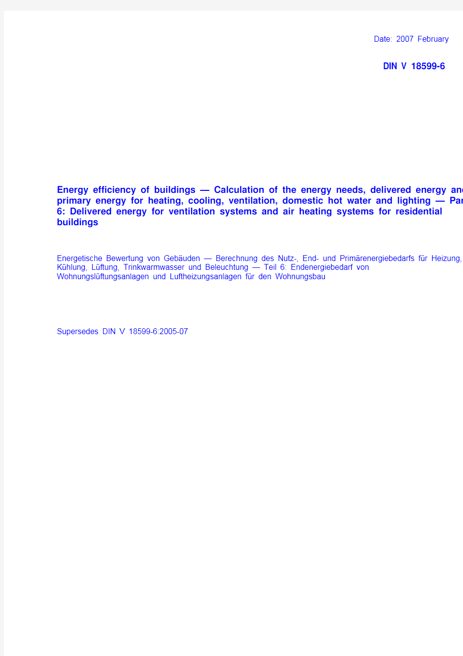
Introduction
When an energy balance is calculated in accordance with the DIN V 18599 series of prestandards, an integrative approach is taken, i.e. the building, the use of the building and the building’s technical installations and equipment are assessed together, taking the interaction of these factors into consideration. In order to provide a clearer structure, the DIN V 18599 series of prestandards is divided into several parts, each having
a particular focus. Figure 1 provides an overview of the topics dealt with in the individual parts of the series.
Figure 1 — Overview of the parts of DIN V 18599
DIN V 18599-6:2007-02
1 Scope
The DIN V 18599 series of prestandards provides a method of calculating the overall energy balance of buildings. The described algorithm is applicable to the calculation of energy balances for:
?residential buildings and non-residential buildings;
?planned or new building constructions and existing buildings.
The procedure for calculating the balances is suitable for:
?balancing the energy use of buildings with partially pre-determined boundary conditions;
?balancing the energy use of buildings with freely selectable boundary conditions from the general engineering aspect, e.g. with the objective of achieving a good comparison between calculated and measured energy ratings.
The balance calculations take into account the energy use for:
? heating,
? ventilation,
?air conditioning (including cooling and humidification),
?heating the domestic hot water supply, and
? lighting
of buildings, including the additional electrical power input (auxiliary energy) which is directly related to the energy supply.
This document describes a method of calculating the values for ventilation and air heating systems of residential buildings.
This document describes the energy use of ventilation systems and air heating systems for residential buildings in conjunction with individual subsystems (control and emission, distribution, storage and generation). For this purpose, both the heat losses and the auxiliary energy of the individual subsystems are determined and, provided that these occur within the heated zone, are made available for the subsequent calculations described in DIN V 18599-1 and DIN V 18599-2.
It is also possible to determine the use of subsystems for heat delivery to DIN V 18599-5 and DIN V 18599-8 and vice-versa. In such cases, the initial output data from DIN V 18599-1 and DIN V 18599-2, while the boundary conditions are obtained from DIN V 18599-10. It is also possible to calculate the energy balances of several building zones in which there are more than one units to be balanced.
Figure 2 shows the scope of the present document as a diagram. For the reader’s orientation, all other parts of the DIN V 18599 series of prestandards contain an illustration similar to Figure 2 as shown here, and in which the respective energy components dealt with are shown in colour.
9
DIN V 18599-6:2007-02
10 Figure 2 — Content and scope of DIN V 18599-6 (schematic diagram)
The required energy use can be calculated using either the methods described in clauses 6 to 9 or by other methods (e.g. DIN V 4701-10, DIN V 4701-12 and PAS 1027), provided these alternative methods deliver equivalent results under comparable boundary conditions (see DIN V 18599-10). The assumptions and boundary conditions on which these calculations are based shall be recorded systematically and shall apply to the total annual heating need Q h,b.
It is assumed that all system components have been designed according to the current rules of technology. The energy need values calculated using this procedure cannot be used to size individual components. Mechanical ventilation systems for residential buildings are classified into groups in accordance with DIN 1946-6 (see Figure 3). It is assumed that these systems are being operated as intended and in keeping with accepted best practice. Special guidance (e.g. in the planning and design of ventilation systems for residential buildings) is given in DIN 1946-6.
DIN V 18599-6:2007-02
11
Figure 3 — System overview of ventilation systems for residential buildings
in accordance with DIN 1946-6
The combination of the ventilation system or air heating system of a residential building with other systems such as heating systems as described in DIN V 18599-5 or domestic hot water systems as described in DIN V 18599-8 is considered, and the respective balances can be calculated.
If the building contains ventilation and air heating systems which are not described in this document, other physically sound algorithms may be used for the assessments, taking this document as a basis.
This document does not include descriptions of systems for cooling and air conditioning of residential buildings nor of ventilation systems for non-residential buildings. These systems are described in DIN V 18599-7.
2 Normative references
The following referenced documents are indispensable for the application of this document. For dated references, only the edition cited applies. For undated references, the latest edition of the referenced document (including any amendments) applies.
DIN V 18599-1, Energy efficiency of buildings — Calculation of the energy needs, delivered energy and primary energy for heating, cooling, ventilation, domestic hot water and lighting — Part 1: General balancing procedures, terms and definitions, zoning and evaluation of energy carriers
DIN V 18599-2, Energy efficiency of buildings — Calculation of the energy needs, delivered energy and primary energy use for heating, cooling, ventilation, domestic hot water and lighting — Part 2: Energy needs for heating and cooling of building zones
DIN V 18599-3, Energy efficiency of buildings — Calculation of the energy needs, delivered energy and primary energy for heating, cooling, ventilation, domestic hot water and lighting — Part 3: Energy need for air conditioning
DIN V 18599-4, Energy efficiency of buildings — Calculation of the energy needs, delivered energy and primary energy for heating, cooling, ventilation, domestic hot water and lighting — Part 4: Energy need and delivered energy for lighting
DIN V 18599-6:2007-02
DIN V 18599-5, Energy efficiency of buildings — Calculation of the energy needs, delivered energy and primary energy for heating, cooling, ventilation, domestic hot water and lighting — Part 5: Delivered energy for heating systems
DIN V 18599-7, Energy efficiency of buildings — Calculation of the energy needs, delivered energy and primary energy for heating, cooling, ventilation, domestic hot water and lighting — Part 7: Delivered energy for air handling and air conditioning systems for non-residential buildings
DIN V 18599-8:2005-07, Energy efficiency of buildings — Calculation of the energy needs, delivered energy and primary energy for heating, cooling, ventilation, domestic hot water and lighting — Part 8: Energy need and delivered energy for domestic hot water systems
DIN V 18599-9, Energy efficiency of buildings — Calculation of the energy needs, delivered energy and primary energy for heating, cooling, ventilation, domestic hot water and lighting — Part 9: Delivered and primary energy for combined heat and power plants
DIN V 18599-10, Energy efficiency of buildings — Calculation of the energy needs, delivered energy and primary energy for heating, cooling, ventilation, domestic hot water and lighting — Part 10: Boundary conditions of use, climatic data
DIN 1946-6, Ventilation and air conditioning — Part 6: Ventilation for residential buildings — Requirements, performance, acceptance (VDI ventilation code of practice)
DIN 4753-8, Water heaters and water heating installations for drinking water and for service water — Part 8: Thermal insulation for water heaters with nominal capacity up to 1000 l — Requirements and testing
DIN EN 255-3, Air conditioners, liquid chilling packages and heat pumps with electrically driven compressors — Heating mode — Part 3: Testing and requirements for marking for sanitary hot water units
DIN EN 308, Heat exchangers — Test procedures for establishing performance of air to air and flue gases heat recovery devices
DIN V 4701-10, Energy efficiency of heating and ventilation systems in buildings — Part 10: Heating, domestic hot water supply, ventilation
DIN V 4701-12, Energetic evaluation of heating and ventilation systems in existing buildings — Part 12: Heat generation and domestic hot water generation
DIN EN 13141-7, Ventilation for buildings — Performance testing of components/products for residential ventilation — Part 7: Performance testing of mechanical supply and exhaust ventilation units (including heat recovery) for mechanical ventilation systems intended for single family dwellings
DIN EN 13141-8, Ventilation for buildings — Performance testing of components/products for residential ventilation — Part 8: Performance testing of unducted mechanical supply and exhaust ventilation units (including heat recovery) for mechanical ventilation systems intended for a single room
DIN EN 14511-2, Air conditioners, liquid chilling packages and heat pumps with electrically driven compressors for space heating and cooling — Part 2: Test conditions
DIN EN 14511-3, Air conditioners, liquid chilling packages and heat pumps with electrically driven compressors for space heating and cooling — Part 3: Test methods
PAS 1027, Energy efficiency of heating and ventilation systems in existing buildings
ISO 13600, Technical energy systems — Basic concepts
Energieeinsparverordnung (EnEV) (German Energy Saving Ordinance) 2002/2004
12
DIN V 18599-6:2007-02
3 Terms, definitions and units
3.1 Terms and definitions
For the purposes of this document, the following terms and definitions apply.
3.1.1
primary energy
calculated quantity of energy, taking into account the energy required outside of the building by the preceding process chains for obtaining, converting and distributing the respective fuels used, in addition to the energy content of the required fuel and the auxiliary energy for the technical building installations
3.1.2
delivered energy (“energy use” in this document)
calculated quantity of energy delivered to the technical building installations (heating system, ventilation and air conditioning system, domestic hot water system, lighting system) in order to ensure the specified room temperature, heat the domestic hot water and ensure the desired lighting quality throughout the year
NOTE This energy includes the auxiliary energy required to operate the technical building installations. The delivered energy is transferred at the “interface” constituted by the external building envelope and thus represents the amount of energy which the consumer requires in order to use the building for its intended purpose under standardized boundary conditions. Against this background, the energy use is expressed individually for each energy carrier.
3.1.3
energy needs
collective term for the energy needs for heating, cooling, domestic hot water, lighting and humidification
3.1.4
energy need for heating
calculated heat energy required in order to maintain the specified thermal room conditions within a building zone during the heating period
3.1.5
energy need for cooling
calculated cooling energy required in order to maintain the specified thermal room conditions within a building zone during periods in which the sources of heat generate more energy than is required
3.1.6
energy need for lighting
calculated energy required to illuminate a building zone with the quality of lighting specified in the usage profile
3.1.7
energy need for domestic hot water
calculated energy required to supply a building zone with the amount of domestic hot water at the required supply temperature specified in the usage profile
3.1.8
energy carrier
substance or phenomenon that can be used to produce mechanical work, radiation or heat or to operate chemical or physical processes
3.1.9
energy efficiency (energy performance)
evaluation of the energy quality of buildings by comparing calculated energy ratings against standard energy ratings (i.e. with economically viable energy ratings from comparable new or renovated buildings) or by
13
DIN V 18599-6:2007-02
comparing measured energy ratings against comparable values (i.e. with mean measured energy ratings from buildings with comparable types of usage)
3.1.10
conditioning
generation of defined conditions in spaces due to heating, cooling, ventilation, humidification, lighting and domestic hot water supply
NOTE Conditioning aims to meet requirements relating to the room temperature, fresh air supply, light, humidity and/or domestic hot water.
3.1.11
conditioned space
space and/or enclosure which is heated and/or cooled to a defined set-point temperature and/or humidified and/or illuminated and/or provided with ventilation and/or domestic hot water
NOTE Zones are conditioned spaces having at least one mode of conditioning. Spaces which have no form of conditioning are called “unconditioned spaces”.
3.1.12
zone
basic unit of space for calculating energy balances
NOTE 1 A zone is a cumulative term for a section of the floor area or certain part of a building having uniform boundary conditions of use and which does not exhibit any relevant differences in the mode of conditioning and other zone criteria. NOTE 2 DIN V 18599-10 contains a compilation of boundary conditions of use.
3.1.13
serviced area
area comprising all those parts of a building which are served by the same technical building system
NOTE A serviced area (heating, domestic hot water, ventilation, cooling, lighting etc.) can cover several zones; a single zone may also include more than one serviced area.
In keeping with the rules for calculating individual part-balances, it may be necessary to determine the energy use of an individual serviced area. The energy values determined for the serviced area are then distributed over the individual building zones as explained in DIN V 18599-1.
3.1.14
building services
technical building systems providing internal climate condition services
NOTE 1 This document deals with heating, cooling, domestic hot water supply, ventilation, humidification and lighting.
A building service may include more than one technical building system.
NOTE 2 For example, the “domestic hot water supply” service includes both central and decentralized systems. Appropriate part-balances are assigned to each of the building services.
3.1.15
system boundary
outer delimitation of a zone
NOTE Rules for determining system boundaries are described in DIN V 18599-1.
3.1.16
envelope or thermal envelope area
outer delimitation of any zone
14
DIN V 18599-6:2007-02 NOTE 1 The envelope or thermal envelope area is the boundary between conditioned spaces and the external air, the ground or unconditioned spaces. The cooled or heated spaces will lose heat or gain heat via this surface and, for this reason, it can be also called the “thermal envelope area”. Spaces which are not heated or cooled, but which have other forms of conditioning (e.g. lighting, ventilation) also have specific envelopes, but these do not contribute to heat transfer. For simplification, the designations “envelope” and “thermal envelope area” are used synonymously.
NOTE 2 The envelope or thermal envelope area is formed by a material boundary, usually by the outer facade, internal surfaces, basement ceiling, ceiling of the top storey or by the roof. Rules for delimiting envelopes are described in DIN V 18599-1.
3.1.17
net floor area, reference area
usable floor area within the conditioned volume of the building
NOTE The net floor area (A NGF) is used as the reference area.
3.1.18
gross volume, external volume (V e)
volume of a building or of a building zone as calculated on the basis of external dimensions
NOTE 1 This volume includes, at least, all the spaces in a building or zone which are directly or (since they are interconnected) indirectly conditioned as required for their function.
NOTE 2 Rules for determining the gross volume are described in DIN V 18599-1.
3.1.19
net volume, air volume V(internal volume)
volume which undergoes air interchange within a conditioned zone or within an entire building
NOTE 1 The net volume is determined on the basis of the internal dimensions, i.e. the volume of the building structure itself is not included.
NOTE 2 The net volume is calculated by multiplying the net floor area by the clear ceiling height. The clear ceiling height is the difference in height between the upper face of the floor and the lower face of the storey floor above or suspended ceiling. As an estimate, (if no internal measurements are taken, for instance) the net volume is calculated using the equation V = 0,8 ×V e, with V e being the gross volume (external volume).
3.1.20
reference internal temperature
mean internal temperature of a building or a building zone on which the calculations of the energy needs for heating and cooling are based. Also the mean temperature based on heating patterns with limited heating in certain sections or at certain times and, where the energy need for cooling is to be calculated, taking into account the permitted temperature variations
NOTE Different temperature values are usually assumed for heating and for cooling, respectively.
3.1.21
external temperature
temperature of the external air, which is determined by meteorological measurement and evaluation and is taken as a basis for the calculations
3.1.22
heat sink
quantity of heat drawn out of the building zone
NOTE This does not include heat removed by means of the cooling system.
15
DIN V 18599-6:2007-02
3.1.23
heat source
quantity of heat with temperatures above the internal temperature, which is fed into the building zone or which is generated inside the building zone
NOTE This does not include controlled heat energy input via the technical systems (heating, ventilation) in order to maintain the set internal temperature.
3.1.24
utilization factor
factor by which the total input from the monthly or annually active heat sources is reduced in order to determine the usable portion of the heat from the respective sources
3.1.25
air volume
net volume
volume subject to air exchange within a zone with thermal conditioning
NOTE It is determined on the basis of the internal dimensions, i.e. the volume of the building structure itself is not included.
3.1.26
air change rate
air flow per unit volume
3.1.27
system losses
losses (heat losses, cooling losses) occurring in technical subsystems between the energy need and the energy use, i.e. losses occurring due to control and emission, distribution, storage and generation
NOTE Where such system losses occur within the conditioned spaces, they are considered to be part of the heat sources or heat sinks.
3.1.28
renewable energy
energy from sources which will not be depleted within the foreseeable existence of the human race (e.g. solar energy (thermal, photovoltaic and for lighting purposes), wind, water and energy from biomass)
3.1.29
calculation period
period for which the balance of relevant energy flows in a building is calculated
NOTE The calculation period for calculating the delivered energy and primary energy use is one year; periods of one month or one day can be used for calculating partial energy values.
3.1.30
auxiliary energy
energy required by systems for heating, cooling, domestic hot water heating, air conditioning (including ventilation) and lighting in order to support energy transformation to satisfy energy needs
NOTE This includes the energy required by pumps, fans, controls, electronics etc., but not the transformed energy. 3.1.31
energy content
amount of thermal energy which is output by complete combustion of a specific quantity of fuel at a constant pressure of 101 320 Pa
NOTE When expressed as the gross calorific value, the energy content includes the latent heat liberated by condensation of water vapour. The net calorific value does not include this latent heat.
16
DIN V 18599-6:2007-02 3.1.32
ventilation system for residential buildings
residential ventilation system
system for supplying fresh air and/or removing exhaust air which conveys external air into the building, and which may include heat recovery and air conditioning
NOTE Systems for supplying fresh air and/or removing exhaust air may be decentralized systems intended for a single room or central supply and/or exhaust ventilation systems.
3.1.33
air heating system for residential buildings
heating system which supplies heat to a zone using only air as the heat carrier
NOTE Air heating systems have at least one heat generator (e.g. a heat pump for extract air heat recovery). In addition, they may include a heat exchanger for heat recovery. Air heating systems can be operated using external air, a combination of external air and recirculated air, or recirculated air only.
3.1.34
control and emission
subsystem in which energy is transferred (e.g. to the space or room), while conforming with the specified requirements (particularly with respect to comfort)
(see DIN V 18599-10)
3.1.35
distribution
subsystem in which the required quantity of energy is transmitted from the generator to the heat control and emission system
3.1.36
storage
subsystem in which the heat contained in a medium is stored
NOTE In residential ventilation systems or air heating systems, this may be effected by a buffer storage tank in conjunction with an extract air/water heat pump.
3.1.37
generation
subsystem which provides the quantity of heat required by the systems
3.1.38
operating time of ventilation systems for residential buildings
time determined on the basis of the daily operating time and the operating time per month
NOTE 1 The operating time per day is expressed in h/d, the operating time per month, in d/month.
NOTE 2 As far as the monthly operating time is concerned, a distinction is made between year-round operation and heating season operation.
NOTE 3 In the case of year-round operation, the residential ventilation system is operated on all days of the year. At times outside the heating season, the air conditioning functions shall bypass any heat recovery system which may be installed; otherwise the heat recovery system shall be shut down outside the heating season.
NOTE 4 In the case of heating season operation, the residential ventilation system is shut down in the summer months (i.e. outside the heating season). By default, the operating time within the heating season is determined from the heating months, i.e. the residential ventilation system is in operation on all days of the heating months; in the following, this method is termed the “heating-months method”. All months for which the energy need for heating has been determined as described in DIN V 18599-2 and in which no ventilation system is used are considered to be heating months.
NOTE 5 As an alternative, the monthly operating time can be determined on the basis of the heating time without ventilation system support as described in DIN V 18599-2. The residential ventilation system is only operated on heating
17
DIN V 18599-6:2007-02
18
days; in the following, this method is termed the “heating-time method”. If the heating-time method is used in the balance calculations, the residential ventilation system is controlled using a suitable reference variable (e.g. external temperature compensation).
3.1.39
product data
manufacturer-specific data on the basis of
— a declaration of conformity to harmonized European specifications or corresponding European directives,
or
— a declaration of conformity to generally recognized technical standards, or
— a building-inspectorate certificate of usability
that is suitable for this calculation procedure
3.1.40
default value
data which can be used for the calculation if no suitable product data are available for the calculation procedure
3.2 Symbols, units and subscripts
Table 1 contains an overview of important symbols which are generally applicable to the overall balance described in the DIN V 18599 series of prestandards. Table 2 lists the subscripts which are used in all balance calculations. Table 3 lists the additional subscripts specified in the present document.
Table 1 — Symbols (used in all calculations in the DIN V 18599 series of prestandards) Meaning Symbol
German English Standard unit f
Faktor factor – Q Energie energy
kWh/a η Nutzungsgrad, Effizienz,
Ausnutzung
performance factor, efficiency, utilization factor – t Zeit, Zeitperiode time, time period, hours h, h/a
A Fl?che area m 2
V Volumen volume m 3
V & Volumenstrom volume flow rate m 3/h
Φ
Leistung, Energiestrom power, energy flow rate W Φ
Lichtstrom luminous flux lm Δ Differenz difference
– γ Quellen/Senken-Verh?ltnis source/sink ratio
– ?
Celsiustemperatur Celsius temperature °C
DIN V 18599-6:2007-02
19
Table 2 — Subscripts (used in all balance calculations in the DIN V 18599 series of prestandards) Meaning Subscript
German English P Prim?r-
primary f End-
delivered b
Nutzenergiebedarf im Geb?ude building energy needs aux Hilfs- auxiliary h
Heizung, Raumheizsystem heating, space heating system h* RLT-Heizfunktion, W?rmeversorgung der
RLT-Anlage
HVAC heating function, heating energy supply for the air conditioning system c Kühlung, Raumkühlsystem cooling, space cooling system c* RLT-Kühlfunktion, K?lteversorgung der RLT-
Anlage HVAC cooling function, cooling energy supply for the air conditioning system
m* Befeuchtung humidification
w Trinkwarmwassersystem (domestic) hot water system
l Beleuchtungssystem lighting system
v Lüftungssystem
ventilation system vh
RLT-Lüftungssystem (warm, als W?rmequelle wirksam) a-c ventilation system (heating) vc RLT-Lüftungssystem (kalt, als W?rmesenke
wirksam)
a-c ventilation system (cooling) rv Wohnungslüftungssystem residential ventilation system ce Verluste der übergabe
control and emission losses d Verluste der Verteilung
distribution losses s Verluste der Speicherung
storage losses g Verluste der Erzeugung
generation losses outg Nutzenergieabgabe des Erzeugers (ce+d+s)
energy output of generator (ce+d+s) reg regenerative Energien
regenerative energy tech technische Verluste (ce+d+s+g) system losses (ce+d+s+g)
T Transmission transmission
V Lüftung ventilation
S solar solar
I innere internal
i innen indoor, internal
e ?u?ere outdoor, external
j , k Index subscript
a Jahr, j?hrlich year, annual
mth Monat, monatlich month, monthly
day
Tag, t?glich day, daily
DIN V 18599-6:2007-02
20
Table 3 — Subscripts (specific to DIN V 18599-6) Meaning
Subscript German English
Energy needs (see clause 5)
mech mechanisch, ventilatorgestützt mechanical, fan-assisted WRG W?rmerückgewinnung
heat recovery WüT W?rmeübertrager
heat exchanger Dicht Dichtheit Lüftungsger?t airtightness of ventilation unit
Frost Abtaubetrieb Lüftungsger?t defrost operating mode of ventilation unit
W?rme W?rmeverluste Lüftungsger?t
heat losses of ventilation unit Heat control and emission (see clause 6)
hydr hydraulischer Abgleich hydraulic balance int
intermittierender Betrieb intermittent operation Radiant
Strahlungseinfluss effect of radiation B Au?enbauteile external building components, elements
C Raumtemperaturregelung room temperature control
L Lufttemperaturprofil air temperature profile
Distribution (see clause 7)
a Anordnung
Arrangement, sequencing Vent Ventilator fan
Storage (see clause 8)
B Bereitschaft
stand-by HP Heizperiode
heating season Pumpe Pumpe
pump Verbindung Verbindung connection
Generation (see clause 9)
WP W?rmepumpe
heat pump Vorw Vorw?rmer
pre-heater NH Nachheizregister
reheating coil Reg Regelung
control EWüT
Erdreich-Zuluft-W?rmeübertrager ground/supply air heat exchanger Gt Gradtagsstunden degree-day hours
Figure 4 shows the system of subscripts used for designating the energy quantities in the balances.
导轨电源的应用行业及安装原理 电源有分为平板电源,导轨式开关电源,稳压电源,单路及多路输出电源。长诚自动化为您提供行业最新消息以及全面的产品适用范围和注意事项,让您的购物变的更简便。导轨电源的应用行业 导轨电源的应用行业十分广泛如医疗行业,机械行业等,最主要用在工业控制行业。导轨式电源性能要求稳定在控制柜中安装安装方便更换容易体积小巧。 导轨电源的安装应用原理 两根间距为d的平行光滑金属导轨间接有电源E,导轨平面与水平面间的夹角θ=30°.金属杆ab垂直导轨放置,导轨与金属杆接触良好.整个装置处于磁感应强度为B的匀强磁场中.当磁场方向垂直导轨平面向上时,金属杆ab刚好处于静止状态.若将磁场方向改为竖直向上,要使金属杆仍保持静止状态,可以采取的措施是(C) A.减小磁感应强度B B.调节滑动变阻器,使电流减小 C.减小导轨平面与水平面间的夹角θ D.将电源正负极对调使电流方向改变 C选项,如果及减小了角度,又减小了电阻可以吗? B未改变前受力分析的BIL=SINθMG B改变后受力分析的SINθMG=COSθBIL及TANθMG=BIL 剩下的你应该会了吧 减小了角度,又减小了电阻也可以,但因为考虑的因素比较多所以一般 不用 把“判断电源正负极”,转化为判断电路中的电流方向。 一、电压表试测法:直接用电压表【试测】,观察指针的偏转方向。若指针正向偏转,则接电压表正接线柱的是电源正极,另一个是负极;若指针反向偏转,则判断结果相反。 二、电流表试测法:用一个用电器跟电流表以串联形式【试测】,判断方法同上。 三、发光二极管试测法:用一个保护电阻与发光二极管串联【试测】,观察发光情况。若二极管发光,则接二极管正极的是电源正极,另一个是负极;若二极管不发光,则判断结果相反 关于导轨电源的详细资料可联系长诚自动化
DIN 导轨式安装单相电子式有功电能表 (液晶红外型) 概述 DDS986型DIN 导轨式安装单相电子式有功电能表系我公司采用微电子技术与专用大规模集成电路,应用数字采样处理技术及SMT 工艺等先进技术全新研制开发的单相两线有功电能表。该表技术性能完全符合IEC 62053-21国际标准中1级单相有功电能表的相关技术要求,能直接精确地测量额定频率为50Hz 或60Hz 三相交流电网中负荷的有功电能的消耗。该表由7位LCD 显示器显示有功用电量,具有可靠性好、体积小、重量轻、外形美观、安装方便等特点。应用广泛与设配套便捷. 功 能 特 点 ● 35mm DIN 标准导轨安装,符合DIN EN 50022标准,或者板前式安装(安装孔中心距63 mm),两种安装方式可由用户任意选择。 ● 7极宽度(模数17.5mm),符合DIN 43880标准。 ● 7位LCD 显示器,标准配置6+1位(999999.1kWh)显示,可选择5+2位显示. ● 2个LED 分别电能脉冲信号(红色)与绿色为红外通讯指示,另外两个为红外发射头和红外接收头。 ● 标准配置含检测负荷电流潮流方向,自动检测负荷电流潮流方向,并由一个单独的LED 指示。 ● 单方向测量单相两线有功电能消耗,与负荷电流潮流方向无关,符合IEC 62053-21标准。 ● 标准配置S 型接线(底端进线,顶端出线),直接接入式使用,可选择CT 接入式使用和PT & CT 接入式使用. ● 标准配置短的接线端子盖,可选择延长型接线端子盖,保护用电安全。 ● 具有红外通讯功能,可通过红外对电表进行抄表和设置. 标准配置通讯协议符合DL/T645-1997标准 技术参数及规格 名 称 型 号 精 度 参比电压 电流规格 单相导轨安装电子式 电能表 (LCD 显示、红外) DDS866 1.0级 220/380V 230/400V 240/415V 1.5(6)A 5(30)A 10(60)A 20(80)A 30(90)A 2.0级 外型及安装尺寸 接线图:
SPECIFICATION DR-120-12DR-120-24DR-120-48MODEL DC VOLTAGE RATED CURRENT CURRENT RANGE RATED POWER OUTPUT VOLTAGE ADJ. RANGE LINE REGULATION LOAD REGULATION SETUP, RISE TIME HOLD UP TIME (Typ.)VOLTAGE RANGE FREQUENCY RANGE EFFICIENCY (Typ.)INPUT INRUSH CURRENT (Typ.)LEAKAGE CURRENT OVER TEMPERATURE SAFETY STANDARDS HARMONIC CURRENT SAFETY &EMS IMMUNITY WORKING TEMP. WORKING HUMIDITY STORAGE TEMP., HUMIDITY TEMP. COEFFICIENT VIBRATION MTBF DIMENSION OTHERS NOTE PACKING OVERLOAD OVER VOLTAGE AC CURRENT (Typ.) 12V 24V 48V 10A 5A 2.5A 0 ~ 10A 0 ~ 5A 0 ~ 2.5A 120W 120W 120W 80mVp-p 80mVp-p 100mVp-p 12 ~ 14V 24 ~ 28V 48 ~ 53V 2.0% 1.0% 1.0%0.5%0.5%0.5%1.0% 1.0% 1.0% 88 ~ 132VAC/176 ~ 264VAC by switch 248 ~ 370VDC 47 ~ 63Hz 80% 84% 85% 29 ~ 33V 905(TSW1)90 5(TSW1) 58 ~ 65V 2.6A/115VAC 1.6A/230VAC COLD START 20A/115VAC 40A/230VAC <3.5mA / 240VAC 105 ~ 150%rated output power 15 ~ 16.5V Protection type :Constant current limiting, recovers automatically after fault condition is removed Protection type : Shut down o/p voltage, re-power on to recover 855(TSW1) Protection type : Shut down o/p voltage, recovers automatically after temperature goes down -10 ~ +60(Refer to output load derating curve)20 ~ 90% RH non-condensing -20 ~ +85 , 10 ~ 95% RH 0.03%/(0 ~ 50 10 ~ 500Hz, 2G 10min./1cycle, 60min. each along X,Y, Z axes; Mounting: Compliance to IEC60068-2-6136.8Khrs min. MIL-HDBK-217F (25) 65.5*125.2*100mm (W*H*D)0.79Kg; 20pcs/16.5Kg/1.29CUFT 1. All parameters NOT specially mentioned are measured at 230VAC input, rated load and 25of ambient temperature. 2. Ripple & noise are measured at 20MHz of bandwidth by using a 12" twisted pair-wire terminated with a 0.1uf & 47uf parallel capacitor. 3. Tolerance : includes set up tolerance, line regulation and load regulation. 4. The power supply is considered a component which will be installed into a final equipment. The final equipment must be re-confirmed that it still meets EMC directives. UL508,TUV EN60950-1 approved UL60950-1,Compliance to EN55011,EN55022 (CISPR22) Class B Compliance to EN61000-3-2,-3Compliance to EN61000-4-2,3,4,5,6,8,11, ENV50204, EN55024, EN61000-6-2 (EN50082-2), heavy industry level, criteria A Features : AC input range selectable by switch Protections: Short circuit / Overload / Over voltage / Over temperature Cooling by free air convection Can be installed on DIN rail TS-35/7.5 or 15UL 508(industrial control equipment)approved LED indicator for power on 100% full load burn-in test Fixed switching frequency at 55KHz 3 years warranty ENVIRONMENT PROTECTION EMI CONDUCTION & RADIATION EMC (Note 4) WITHSTAND VOLTAGE ISOLATION RESISTANCE I/P-O/P:3KVAC I/P-FG:1.5KVAC O/P-FG:0.5KVAC I/P-O/P, I/P-FG, O/P-FG:100M Ohms/500VDC 500ms, 70ms 500ms, 70ms /230VAC /115VAC at full load 36ms 32ms /230VAC /115VAC at full load RIPPLE & NOISE (max.)Note.2VOLTAGE TOLERANCE Note.3
简明操作指南 iTEMP HART TMT112 ?KA193R/09/zh/01.1071122738 DIN 导轨型温度变送器 ?
TMT112 iTEMP? HART? TMT112 DIN导轨型温度变送器目录 1 安全指南 (3) 2 功能 (4) 3 外形尺寸 (4) 4 安装 (5) 5 接线示意图 (6) 6 操作 (8) 7 附件 (10) 8 补充文档 (11)
TMT112 1 安全指南TMT112是一款通用型预设置DIN导轨型温度变送器,可连 接热电阻(RTD)、热电偶(TC)、电阻及电压信号。TMT112 可直接安装在符合 IEC 60715标准的DIN导轨上。 制造商对由于误操作而引起的仪表损坏不承担任何责任。 在防爆区中测量的仪表,单独成册的防爆手册(Ex)是仪表 操作手册的组成部分。必须完全遵守其中规定的安装条件 和电气连接参数要求。 专业人员必须事先仔细阅读仪表操作手册,方可进行仪表 的安装和接线操作。 TMT112温度变送器不可维修。已损坏的仪表,必须遵照 当地的废弃物处置规定进行相应的报废处理。 TMT112 DIN导轨型温度变送器由电源供电,供电电路必 须符合IEC 61010-1标准规定的能量限制电路:“SELV或2 类电路”要求。
TMT112 2 功能在工业温度测量中,基于电子监控和传输控制,将多种输入 信号转换成模拟输出信号。可以通过HART?手操器(DXR275/ 375),或安装有操作软件(Commuwin II、FieldCare或ReadWin? 2000)的PC机对TMT112进行仪表设置。 3 外形尺寸 [mm(inch)]
六种典型电磁导轨的规律解析及应用 电磁导轨问题涉及力学、功能关系、电磁学等一系列基本概念、基本规律和科学思维方法。分清不同性质的导轨,熟悉各种导轨中导体的运动性质、能量转化特点和极值规律,对于吃透基本概念,掌握基本规律,提高科学思维和综合分析能力,具有重要的意义。 一. 发电式导轨的基本特点和规律 如图1所示,间距为l 的平行导轨与电阻R 相连,整个装置处在大小为B 、垂直导轨平面向上的匀强磁场中。质量为m 、电阻为r 的导体从静止开始沿导轨滑下,已知导体与导轨的动摩擦因数为μ。 1.电路特点 导体为发电边,与电源等效。当导体的速度为v 时,其中的电动势为Blv E = 2.安培力的特点 安培力为运动阻力,并随速度按正比规律增大。v r R v l B l r R Blv B BIl F B ∝+=+==22 3.加速度特点 加速度随速度增大而减小,导体做加速度减小的加速运动。 m r R v l B mg mg a )/(cos sin 22+--=θμθ 4.两个极值的规律 当0=v 时,0=B F ,加速度最大为)cos (sin θμθ-=g a m 当0=a 时,∑=0F ,速度最大。根据平衡条件有) (cos sin 22r R v l B mg mg m ++ =θμθ,所以, 最大速度为2 2) )(cos (sin l B r R mg v m +-=θμθ 5.匀速运动时能量转化规律 当导体以最大速度匀速运动时,重力的机械功率等于安培力功率(即电功率)和摩擦力功率之和,并均到达最大值。 ?? ? ????=+=+====+=θμθcos )()(sin 2 2 m f m m m m m m F m G f F G mgv P r R I r R E E I v F P mgv P P P P 当μ=0时,重力的机械功率就等于安培力功率,也等于电功率,这是发电导轨在匀速运动过程中,最基 本的能量转化和守恒定律。 )() (sin 2 2 r R I r R E E I v F mgv m m m m m m m +=+===θ 二.电动式导轨的基本特点和规律 如图2所示,间距为l 的平行导轨水平放置,与电动势为E 、内阻为r 的电源连接,处在大小为B 方向竖直向上的匀强磁场中。当电路闭合时,质量为m 、电阻为R 的导体从静止开始沿导轨运动,与导轨的动摩擦因数为μ。
热电偶接线端子可安装于DIN导轨,方便进行检查和故障 排除 ?螺丝接线端可提供安全且免维护的连接 ?可用于K、J、T、E、N、R/S和U型分度号热电 偶 ?内置小型热电偶母连接器,可进行检查和故障排 除 ?全封闭式—无需使用端板 ?可进行DIN导轨安装—宽度小,仅10.7 mm ?带有分度号与"+,-" 连接标识 ?内含书写窗 全新DRTB系列热电偶接线盒采用热电偶级合金加工而成,保证可提供精确读数。内置SMP 兼容母插座可插接小型热电偶连接器。母连接器让使用者可以连接到手持式仪表,用于数据采集、质保合规、功能研究以及故障排除安装或维修等应用。 塑料外壳采用灰色聚酰胺6.6热塑性树脂加工而成,达到UL 94 V0等级(85°C)。这些热电偶接线端为全封闭式,无需使用任何端板。螺钉和夹子都经过镀锌,它们配合使用可提供一种无振动、免维护、抗腐蚀的连接。 DRTB接线盒可安装在标准35 mm DIN导轨或32 mm G型导轨中,可用分度号类型以及正极(+)和负极(-)连接标识它们。导线入口为漏斗形,即便是标准导线,也能实现导线快速插接。 规格: 接线端宽度:10.7 mm (0.422") 接线端长度/高度:51 mm (2.008")/42.3 mm (1.666") 安装到35 x 7.5 mm/ 35 x 15 mm DIN导轨中的高度:43.5 mm (1.713")/51 mm (2.009") 导线最大尺寸:12 AWG/2.5 mm2 裸线长度:8 mm (0.31") 扭矩(Nm (in-lb)):0.4 (3.54) ±10% 额定温度:-40 ~ 85°C (-40 ~ 185°F)
Technical Data /4The Types of Linear Rail System /46SBI High-load Linear Rail System /48SBI-FL/FLL /68SBI-SL/SLL /70SBI-HL/HLL /72SBI-CL/CLL /74SBI-FV /76SBI-SV /78SBG Standard Linear Rail System /80SBG-FL/FLL /100SBG-SL/SLL /102SBS-SL/SLL/HL/HLL /104SBS-FV /106SBS-SV /108SPG / SPS Spacer Linear Rail System /110SPG-FL/FLL /112SPG-SL/SLL /114SPS-SL/SLL/HL/HLL /116SPS-FV /118SPS-SV /120Miniature Linear Rail System /122SBM/SBML /132SBMW /134 Linear Rail System Technical Data /2SBC Precision Rolled Ball Screw /46STK/STC /50SLK /52MBS /54DIN Standard SBC Precision Rolled Ball Screw /56DK /60DH /62Ground Ball Screw for FA- SFA Series /64 Ball Screw Fixed-End Support Unit /2FK /4FK-DS(T)/6BK /8BK-DS /10EK /12AK /14Supported-End Support Unit /16FF /18FF-DS(T)/20BF /22BF-DS /24EF /26AF /28Recommended Screw End Machining /30 Support Unit Technical Data /2Asia type Ball Bushing /18 SB, SB-L, SB-AJ, SB-OP /20~27SBF, SBF-L /28~31SBK, SBK-L /32~35SBH, SBH-L /36~39SBF-A, SBF-LA /40~43SBK-A, SBK-LA /44~47SBH-A, SBH-LA /48~51SBFC, SBKC, SBHC /52~57SC, SC-L /58~61Europe type Ball Bushing /62 SBE, SBE-L, SBE-AJ, SBE-OP /64~71SBFE, SBFE-L /72~75SBKE, SBKE-L /76~79SBFCE, SBKCE /80~83SCE, SCE-L /84~87Compact type Ball Bushing / Option /88 KH /89 Linear Bushings CONTENTS
设备参数: DIN-AP2导轨安装2系列自动化控制主机CPU: 飞思卡尔32位ColdFire?微处理器 存储器:SDRAM: 32MB NARAM: 256KB FLASH: 8MB Memory Card:可拓展至2GBMMC存储卡 端口:I/O1-8:数字输入:0-24V直流,输入阻抗20KΩ 数字输出:250M A0-24V直流 模拟输入:0-10V直流,输入阻抗20KΩ 模拟输出:可编程5V2KΩ电阻 RELAYS1-4:1A MP 30V交流/直流 COMPUTER:B类USB1.1母口 NET:C RESNET主/从接口 COM1-2:RS-232接口 LAN:10/100M自适应网卡 IR/SERIAL1-4:红外输出或单向RS232输出 耗电量:8W 产品尺寸:9.42 CM(H)×15.90 CM(W)×5.80 CM(D)
DIN-PWS50导轨安装50W系统电源模块输出供电:单个输出端口:50W(2.08Amps@24V DC) 模块输出端口:50W(2.08Amps@24V DC) 供电需求:60W@220V AC50/60H Z 端口:NET3:3个C RESNET供电接口,2A@24V直流INPUT2:220V50/60H Z,同向双路供电 FUSE:直流输出保险丝,T3.15AH,熔断过载:70W 产品尺寸:9.42 cm(H)×10.60 cm(W)×5.80 cm(D)
DIN-IO8导轨安装输入输出模块 端口:I/O1-8:数字输入:0-24V直流,输入阻抗20KΩ 数字输出:250M A0-24V直流 模拟输入:0-10V直流,输入阻抗20KΩ 模拟输出:可编程5V2KΩ电阻 NET:C RESNET主/从接口 产品尺寸:9.42 cm(H)×10.60 cm(W)×5.95 cm(D) 耗电量:1.5W
静压导轨系统和滚动直线导轨系统具有相同的安装尺寸
静压导轨系统 页产品概览静压导轨系统 (2) 特性通过静压油膜阻尼振动 (3) X-life (3) 功能 (4) 这种方案的优势 (4) 现有设计 (5) 运行条件 (5) 密封 (5) 耐腐蚀保护 (5) 工作温度 (5) 设计与安全指南互换性 (6) 预载 (6) 摩擦 (6) 刚度 (7) 静压导轨系统的安装 (7) 液压配置 (8) 导轨固定孔布置形式 (13) 相邻结构设计 (14) 精度定位台阶高度和圆角半径 (16) 精度等级 (16) 导轨固定孔的位置公差和导轨的长度公差 (18) 订货举例、订货号安装孔对称 (19) 尺寸表静压导轨系统 (20) Schaeffler Technologies TPI 1491
2TPI 149Schaeffler Technologies 产品概览静压导轨系统 和滚柱直线导轨具有相同的安装尺寸HLE45-A-XL 00089D 7E
静压导轨系统 特性标准直线导轨的滑块不能阻尼振动。为了有效阻尼振动, 滚柱直线导轨系统RUE-E需要使用额外的阻尼滑块RUDS-D, 阻尼滑块布置在承载滑块中间。但是为了最有效的阻尼振动, 阻尼滑块必须布置在振幅最大的位置,因此需要很好的掌握 振动的形式。 通过静压油膜阻尼振动对于阻尼、动态刚度和承载能力要求非常高的应用,现在可以 使用静压导轨系统,基于已经验证的滚柱直线导轨系统RUE..-E, 尺寸45。 带有预载的静压导轨系统是一个完整的单元,本身带有很好的 阻尼能力,不需要额外的阻尼部件。 静压导轨系统HLE45-A-XL 具有X-life的品质。 静压导轨系统阻尼值高达 470000kg/s 同时,它具有与对应型号 的滚动导引系统几乎一样高的拉伸和压缩刚度。当静压导轨系统 用在机床上时,可以使机床具有更高的切削量、更好的表面加工 质量和更长的使用寿命。 滑块鞍板承载油腔中特殊的青铜涂层,可以保证静压导轨系统具 有优良的安全运行特性,这意味着在过载和供油压力不足的工作 条件下静压导轨系统不会被损坏。 Schaeffler Technologies TPI 1493
灯具用电源导轨系统安全要求 标准号:GB13961-2003/IEC60570:1995 替代情况:替代$False$ 发布单位:国家质量监督检验检疫总局 起草单位:惠州雷士工业发展有限公司,上海市照明灯具研究所 发布日期: 实施日期: 更新日期:2007年10月04日 前言 本标准的全部技术内容为强制性。 本标准是根据国际电工委员会IEC60570:1995《灯具用电源导轨系统》以及第1号修正件(1998)和第2号修正件(2000)修订的,在技术内容和编写格式上与IEC60570《灯具用电源导轨系统》完全等同。 本标准与GB/T13961-1992的主要差异是,本标准等同采用IEC60570:1995,全部技术内容均为安全要求。GB/T13961-1992《灯具用电源导轨系统》等效采用IEC60570:1985及第1号修订件(1990),在采用了其中的安全要求后,还包括性能要求和检验规则。 本标准应与GB7000.1-2002一起使用。 本标准从生效之日起,同时代替GB/T13961-1992。 本标准由中国轻工业联合会提出。 本标准由全国照明电器标准化技术委员会灯具标准化分技术委员会归口。 本标准起草单位:惠州雷士工业发展有限公司,上海市照明灯具研究所。 本标准主要起草人:胡永宏、於立成、汪永锡、陈超中、施晓红。 本标准于1992年首次发布,本版是第1次修订。 IEC前言 1)IEC(国际电工委员会)是一个由各国电工委员会(IEC国际委员会)组成的世界性国际标准化组织。IEC的宗旨是促进对有关在电气和电子领域内的所有标准化问题的国际合作。为此,IEC除组织其他活动之外,还出版国际标准。国际标准委托给技术委员会制定。任何对所讨论的问题感兴趣的IEC国家委员会都可以参加制定工作。与IEC建立联系的国际组织、政府组织和非政府组织也可以参加这一制定工作。IEC按照与国际标准化组织(ISO)达成的协议规定与其保持密切的合作。 2)IEC关于技术问题的正式决议或协议,是由对该问题感兴趣的国际委员会的代表参加的技术委员会制定的,表达了国际上尽可能接近一致意见。
一、行业介绍 随着经济的飞速发展,各行各业对电的需求越来越大,电力资源紧缺和不同时间用电量不均衡的现象依然严重。随着智能电网建设的进一步推进,电子式电表将呈现出完全取代感应式电表的趋势,并逐步向“智能电表”过渡。我司生产的导轨表在终端计量时,根据电压、电流相序或同名端接线错误无需改变已有的外部接线,通过软件方法自动调整和自适应已有的接
线方式,将错误采样点信号取反后作为交流采样值,在用电终端计量应用实现自适应交流输入信号功能。 二、产品概述: 电力计量类仪表适用于低压计量的交流电参数及有功电度、无功电度,具有测量精度高、性能稳定可靠、长寿命、体积小、重量轻、功耗低、操作简便、易于实现管理功能的扩展、一表多用等特点。可广泛应用于电力行业的电能测量及用电自动化管理领域,如楼宇、商场、会展中心、学校、机场、港口、工厂、写字楼及公共设施等场所。 导轨式安装电能表是江西华健电力工业公司集多年的电表设计经验,所推出的新一代微型智能电能表,它用于380V/220V终端照明系统,采用标准DIN35mm导轨式安装,结构模数化设计,宽度与微型断路器匹配,可方便安装于照明箱内。 电表采用LCD显示,测量电能及其它电参量,可进行时钟、费率时段等参数设置,并具有电能脉冲输出功能。可用RS485通讯接口与上位机实现数据交换。 导轨式安装电能表具有体积小巧、精度高、可靠性好、安装方便等优点,性能指标符合国标GB/T 17215、GB/T 17883和电力行业标准DL/T614对电能表的各项技术要求,适用于政府机关和大型公建中对电能的分项计量,也可用于企事业单位作电能管理考核。 三、产品执行标准: 符合GB/T17215.321-2008和IEC62053-21国际标准中1级和2级静止式交流有功电能表相关技术要求。采用LCD显示,具有电能脉冲输出功能;可用RS485通讯接口与上位机实现数据交换,极大地方便了用电自动化管理。采用微电子技术计量电能,电能表由分压器取得电压采样信号,分流器取得电流采样信号。该产品适应电压范围宽、可靠性高、寿命长、精度高、功耗低,并且具有防窃电等功能。 ★GB/T 17215.321-2008 交流电测量设备-特殊要求-第21部分:静止式有功电能表(1级和2级) ★GB/T 17215.322-2008 交流电测量设备-特殊要求-第22部分:静止式有功电能表(0.2S级和0.5S级) ★GB/T 17215.323-2008 交流电测量设备-特殊要求-第23部分:静止式无功电能表(2级和3级) ★GB/T 17215.211-2006 交流电测量设备-通用要求、试验和试验条件-第11部分:测量设备 四、产品参数及功能介绍: 电气特性 参比电压AC 220V,AC 3×57.7/100V,AC 3×100V,AC 3×220/380V 正常工作电压0.9 Un~1.1Un 极限工作电压0.7 Un~1.2Un 电流规格 1.5(6)A,5(20)A,10(40)A,20(80)A 启动电流0.4%Ib(直接接入),0.2%In(经CT接入) 参比频率50/60Hz 准确度等级有功0.5S级或1级 电压回路功耗≤1W,5VA(每相) 电流回路功耗≤1VA(每相)
导轨式开关电源并联和冗余技术在实践中的应用 https://www.doczj.com/doc/1815913502.html,2007/4/29 21:46:12 中国自动化学会专家咨询工作委员会供稿 随着工业控制系统的不断大型化、复杂化及综合化,对于控制系统的能源的提供者—工业导轨式开关电源的要求也越来越高了,其集中体现在如何提供大功率的开关电源和如何提高导轨式开关电源的使用的可靠性,为了达到这个目的,导轨式开关电源的并联技术和冗余功能得到了很大的发展。市场上也出现了不少具有并联和冗余功能的导轨式开关电源。但是在生产实践中如何正确地使用和选择导轨式开关电源来实现并联和冗余的功能,仍存在不少问题。比如说:如何能实现100%的冗余功能,不同功率的电源在并联时会产生什么样的问题,电源内部的调节性能对并联运行的电源产生的影响,并联电源安装位置及排列对电源使用寿命的影响,以及采用不同电源启动时间对并联运行可能带来的后果等。本文将对实践中使用导轨式开关电源并联和冗余技术的问题作些探讨。 1 输出电压连接方法对并联运行电源的影响 由于在电源设计中,输出接线端子一般都按单个电源的最大容量来计算和选定的,因此电源并联运行时,各电源的输出端电压不能直接地连接,这样连接的终端会出现过载现象。PULS电源采用了二个输出端子,如图1所示。从电源单元到负载的连接线应使用相同长度和横截面的导线。同时输出电压必须连接在一个公共的接线端上。这样保证每个电源不会在传输导线上产生不同的电压降,避免输出回路电流的产生。采用被动式均流技术的并联运行时各个并联电源的输出电压值必须完全一致,为了达到这个目的,许多可并联的开关电源输出电压是可调的,如PULS 电源的输出为24~28V可调。这样在所有并联的电源接上负载以前,各个开关电源的输出电压就可调整到一致的电压值。
网站首页 / 产品目录 / 环保线槽 / DI N 导轨 钢质导轨 DIN 导轨 钢质导轨 TS-357.51.0/TS-35151.5 介绍: 产品材质:优质高强度冷轧钢电镀。产品标准:欧洲EN50022 颜色种类:镀镍黄色,镀白锌(ROHS 环保型)。工作温度:-40°C 持续高温至100°C 使用方法:固定于面板后即可安装电器。 产品特性: 具美观及抗重压之功能,尺寸十分精确,耐腐蚀。定制长度或孔位有起订量要求,环保型ROHS 为镀白锌规格。手动导轨工具型号:TS-1(357.5),TS-2 (3515)液压多规格导轨工具型号:TS-5 DIN 导轨钢质导轨U 型导轨导轨 型号 Item No. 外宽/外高/厚度/长度-孔宽长 电镀/材质 配套工具包装/箱 din 导轨 钢质导轨 TS-1/TS-5 TS-35/7.5系列 TS-35/7.5/1.0/1M-615彩锌冷轧钢50M TS-35/7.5/1.0/1M-515彩锌冷轧钢50M TS-35/7.5/1.0/1M-525彩锌冷轧钢50M TS-35/7.5/1.0/1M/W-615环保白锌冷轧钢50M TS-35/7.5/1.0/1M/W-515环保白锌冷轧钢50M TS-35/7.5/1.0/1M/W-525环保白锌冷轧钢50M TS-35/7.5/1.0/2M-615彩锌冷轧钢100M TS-35/7.5/1.0/2M-515 彩锌冷轧钢 100M 产品规格
TS-35/7.5/1.0/2M-525彩锌冷轧钢100M TS-35/7.5/1.0/2M/W-615环保白锌冷轧钢100M TS-35/7.5/1.0/2M/W-515环保白锌冷轧钢100M TS-35/7.5/1.0/2M/W-525环保白锌冷轧钢100M TS-35/7.5/1.0/1M-N彩锌冷轧钢-无底孔50M TS-35/7.5/1.0/1M/W-N环保白锌冷轧钢-无底孔50M TS-35/7.5/1.0/2M-N彩锌冷轧钢-无底孔100M TS-35/7.5/1.0/2M/W-N环保白锌冷轧钢-无底孔100M TS-35/15系列 TS-35/15/1.5/1M-615彩锌冷轧钢 TS-2/TS-530M TS-35/15/1.5/1M/W-615环保白锌冷轧钢30M TS-35/15/1.5/2M-615彩锌冷轧钢60M TS-35/15/1.5/2M/W-615环保白锌冷轧钢60M TS-35/15/1.5/1M-N彩锌冷轧钢-无底孔30M TS-35/15/1.5/1M/W-N环保白锌冷轧钢-无底孔30M TS-35/15/1.5/2M-N彩锌冷轧钢-无底孔60M TS-35/15/1.5/2M/W-N环保白锌冷轧钢-无底孔60M TS-15/5.5系列 TS-15/5.5/1.0/1M-412彩锌冷轧钢100M TS-15/5.5/1.0/2M-412彩锌冷轧钢200M TS-15/5.5/1.0/1M/W-412环保白锌冷轧钢100M TS-15/5.5/1.0/2M/W-412环保白锌冷轧钢200M TS-15/5.5/1.0/1M-N彩锌冷轧钢-无底孔100M TS-15/5.5/1.0/2M-N彩锌冷轧钢-无底孔200M TS-15/5.5/1.0/1M/W-N环保白锌冷轧钢-无底孔100M TS-15/5.5/1.0/2M/W-N环保白锌冷轧钢-无底孔200M 图片介绍
DIN导轨检验标准 1.0 目的 本标准适用于公司产品用电气安装导轨的检验。完善公司质量作业制度,规范进料的过程检验方式,确保进料质量满足公司及客户要求。 2.0 范围 本规范适用于我司采购的电气安装导轨的质量验收。 3.0 职责 3.1 质检科负责组织上述检验活动的实施; 3.2 采购科负责对采购件和供应商的沟通; 3.3 生产科负责对采购的使用中不良信息反馈。 4.0技术要求 4.1外观 ①表面不应有锈斑,表面镀层应光滑、色泽均匀,锐边倒钝。应连续、无漏涂、气泡、剥落、裂纹、麻点、夹杂物等缺陷,不允许存在粗沉积物、附着物。但一些小的黄色斑点、水印及接触印痕、搬运时产生的碰划痕(不允许划破涂层)是允许的,不能外露基体材料. ②颜色种类:彩锌、环保白锌等。采用的钢材是冷轧板镀锌、钢制轨道, 材质韧性好。 5.2尺寸及公差 ①一般标准是:1.0mm厚度,宽度:35mm常用的有: ②螺丝孔采用椭圆孔,孔径标准、长度、厚度以采购规格为主; ③尺寸误差以GB/T1804 M级为准;如其他方面满足且又不影响使用个别误差可方宽至自由公差±0.8mm 4.3电镀层(冷镀)的分级号、最小局部厚度表
(备注:以实际采购为准) 4.4盐雾试验 中性盐雾试验24小时(乙酸盐雾试验8小时)无点蚀、生锈等现象。 4.5商标应清晰,便于识别。 5.0检验与判定 5.1外观检验 ①锌层应该是连续的,并尽可能的均匀、光滑;表面无严重的碰伤现象。 ②金属国定导轨表面的商标应清晰,印字内容正确。 5.2尺寸检验、盐雾试验应符合上述检验技术标准。 附加说明由山东大徍机械有限公司负责起草并解释; 编制:审核:批准: 日期:2020年12月22日 主要检验:1.尺寸符合技术要求或相关标准 2.镀锌的符合盐雾试验时间要求 3.外观无机械碰伤,标识清晰。
施耐德模块型导轨式开关电源(60W 到 240W 单相开放式开关电源 - ABL1系列,7W 到 960W 单相和三相工业开关式电源 - Phaseo ABL8,平板式开关电源 - ABL2) 优势 ABL-6T变压器保证了电源和用电设备之间的隔离。整个系列都带有地线屏蔽,以便减少电磁干扰的扩散,提高用户的安全性 ABL-6T变压器保护等级为1级,供货时没有机罩,保护等级为IP20 应用范围 ABL-6T系列单相变压器用来向电器设备控制电路供电,其电源来自230或400V、50或60Hz市电电源符合IEC 61558-2-6,EN61558-2-6标准,且通过了UL认证 性能描述 绕组由无溶剂树脂经过真空浸渍,初级有单绕组和双绕组两种形式 最高无降容工作温度为500C 可直接安装也可以导轨安装 整个系列都装有地线屏蔽,安全性高 覆盖25至2500VA的功率范围 我公司是施耐德电气全国代理商,产品有: 开关电源,空气断路器,塑壳断路器,小型断路器,接触器,继电器, 负荷开关,按钮指示灯,PLC等,欢迎您来电咨询施耐德Schneider 特价库存促销:ATV31H037N4A,ATV31H055N4A,ATV31H075N4A,ATV31HU11N4A 来电议价。 施耐德ABL6优化型安全隔离变压器 订货号输入电压次级输出电压额定功率 ABL6TS02J AC 230~400V 单绕组12V AC 25 VA ABL6TS02B AC 230~400V 单绕组24V AC 25 VA ABL6TS02G AC 230~400V 单绕组115V AC 25 VA ABL6TS02U AC 230~400V 单绕组230V AC 25 VA ABL6TS04J AC 230~400V 单绕组12V AC 40 VA ABL6TS04B AC 230~400V 单绕组24V AC 40 VA ABL6TS04G AC 230~400V 单绕组115V AC 40 VA ABL6TS04U AC 230~400V 单绕组230V AC 40 VA ABL6TS06J AC 230~400V 单绕组12V AC 63 VA ABL6TS06B AC 230~400V 单绕组24V AC 63 VA ABL6TS06G AC 230~400V 单绕组115V AC 63 VA ABL6TS06U AC 230~400V 单绕组230V AC 63 VA ABL6TS10J AC 230~400V 单绕组12V AC 100 VA ABL6TS10B AC 230~400V 单绕组24V AC 100 VA
远程 I/O R3 系列 机型: R3-BS①② ①、②在下列代码中选择。 (例如: R3-BS10/CE) ①插槽数 02: 2个插槽 04: 4个插槽 06: 6个插槽 08: 8个插槽 10: 10个插槽 12: 12个插槽 14: 14个插槽 16: 16个插槽 ②附加代码 ◆适用标准 不写入: 不符合CE /CE: 符合CE R3-BS02 : 2台 R3-BS04 : 4台 R3-BS06 : 6台 R3-BS08 : 8台 R3-BS10 : 10台 R3-BS12 : 12台 R3-BS14 : 14台 R3-BS16 : 16台 使用湿度范围: 30~90%RH(无冷凝) 使用大气条件: 无腐蚀性气体和严重尘埃 安装: 壁面安装或DIN导轨安装 重量(未插入I/O模块时): 约100g(可插入2台) 约150g(可插入4台) 约200g(可插入6台) 约250g(可插入8台) 约350g(可插入10台) 约400g(可插入12台) 约450g(可插入14台) 约500g(可插入16台) 100MΩ以上/500V DC 隔离强度: 内部电源?信号-地面间 2000V AC 1分钟 电磁兼容指令(EMC指令)(2004/108/EC) EMI EN 61000-6-4:2007 EMS EN 61000-6-2:2005
I/O模块的右侧或底座的右侧。 ■R3-BS04、BS06、BS08、BS10、BS12、BS14、BS16 尺 寸 机 型 A R3-BS04112R3-BS06168R3-BS08224R3-BS10280R3-BS12336R3-BS14392R3-BS16 448
? 具有球形接头的通用机盒支架、适合用于自行车杆安装的固定环、带有天鹅颈式的支架并带有用于紧固在玻璃面和光滑表面的吸盘等。 ?DIN 标准导轨固定件根据 DIN EN 60715 TH35 和 G32。 ?用于安装于圆管的卡夹,直径至 ? 32 mm 或标准导轨根据 DIN EN ISO 19054. 类型 A9220029 Holding device, ball joint ABS (UL 94 HB)black 30x54x75mm A9220039 Holding device, bicycle PC black 38x57x42mm A9220049 Holding device, flexible swan neck with suction pad black 190x70x70mm A9220059 Holding device, secured with suction pad black 133x70x70mm
A9220079 Gripper without holding element black 120x97x67mm B1300017 Fastening element for DIN-Rails PA 6 off-white RAL 9002B1300019 Fastening element for DIN-Rails PA 6 black RAL 9005B4308237 Holding clamps PA 6 off-white RAL 9002 B4308238 Holding clamps PA 6 lava B6811751 DIN rail adapter PA 66 (UL 94 V-0)black RAL 9005 需加附件使产品完整 A9220019 Adapter for holding device (4-claws system)ABS (UL 94 HB)black 57x42x6mm 保留技术更改可能性。 ? OKW 机盒系统, Buchen/德国。