Journal of Power Sources 146(2005)
107–110
Applications of high power density lithium ion batteries
T.Horiba a ,?,T.Maeshima a ,T.Matsumura a ,M.Koseki a ,J.Arai b ,Y .Muranaka b
a Shin-Kobe Electric Machinery Co.,Ltd.,Okabe-machi Ohsato-gun,Saitama 369-0297,Japan b
Hitachi Research Laboratory,Hitachi,Ltd.,Ohmika-cho Hitachi,Ibaraki 319-1292,Japan
Available online 20June 2005
Abstract
In 2003,we developed a new type of lithium ion battery for the light vehicle application,in which 14cells of 7Ah were integrated into a battery pack.It has the high rate discharge capability up to 5C rate (35A),a energy density of 74Wh kg ?1,and the low temperature discharge capacity at ?5?C more than 90%of that at 25?C.The life cycle test of 100%depth of discharge (DOD)at 35?C showed the capacity fading around 10%after 500cycles,which con?rmed much longer practical life than 2years.
Recently,we have developed a new high power cell.It has the capacity of 5.5Ah,and has the output power density of 3000W kg ?1at 50%state of charge (SOC)and at 25?C for 5s discharge basis,and the input power density of 2200W kg ?1at the same conditions.The new cells showed much less increase in direct current resistance (DCR)in both the cycle life test and the storage life test than the cells developed before,which consequently implied much longer calendar life than our previous ones developed in 2000.?2005Elsevier B.V .All rights reserved.
Keywords:Direct current resistance;Lithium ion battery;Calendar life
1.Introduction
We have been developing lithium ion batteries since the beginning of 1990s,as a member of national project of Japan,named The Development of Dispersed-Type Battery Energy Storage Technology.We have been concentrating on the manganese-based positive electrode materials in the project [1].By utilizing the results developed in the project,we have released large capacity cells of 90Ah for electric vehicle (EV)application [2]and high power cells of 3.6Ah for hybrid electric vehicle (HEV)application [3].They were applied to commercial vehicles in 2000[4].Among them,we expected the application of high power density lithium ion batteries to be the most promising one,for it takes the advantage of the most outstanding feature of lithium ion batteries quite well.Recently,we have developed two types of improved lithium batteries.One is the high energy density and medium rate battery for light vehicle application,and the other is the high power density cell for the HEV application.
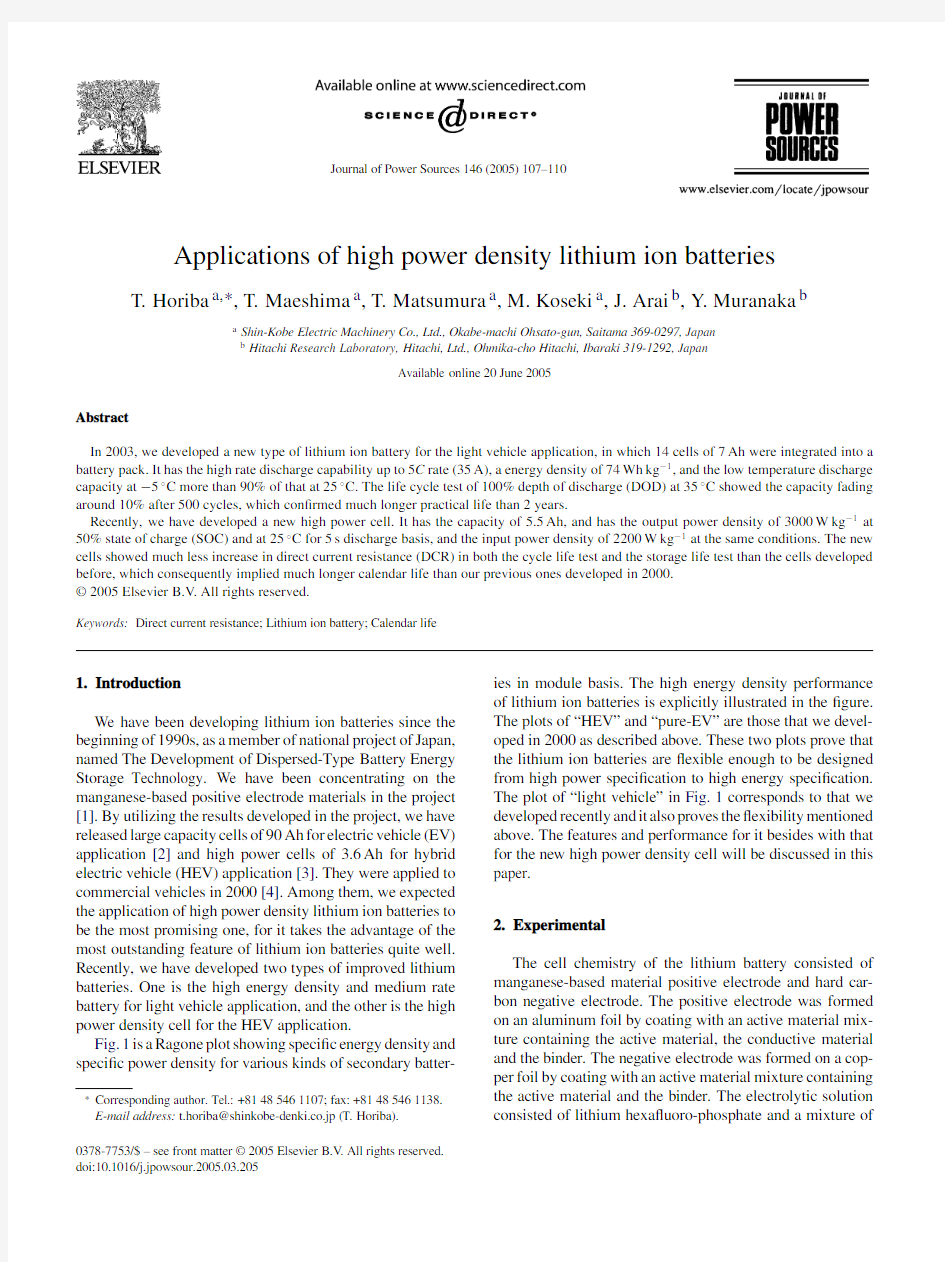
Fig.1is a Ragone plot showing speci?c energy density and speci?c power density for various kinds of secondary batter-?
Corresponding author.Tel.:+81485461107;fax:+81485461138.E-mail address:t.horiba@shinkobe-denki.co.jp (T.Horiba).
ies in module basis.The high energy density performance of lithium ion batteries is explicitly illustrated in the ?gure.The plots of “HEV”and “pure-EV”are those that we devel-oped in 2000as described above.These two plots prove that the lithium ion batteries are ?exible enough to be designed from high power speci?cation to high energy speci?cation.The plot of “light vehicle”in Fig.1corresponds to that we developed recently and it also proves the ?exibility mentioned above.The features and performance for it besides with that for the new high power density cell will be discussed in this paper.
2.Experimental
The cell chemistry of the lithium battery consisted of manganese-based material positive electrode and hard car-bon negative electrode.The positive electrode was formed on an aluminum foil by coating with an active material mix-ture containing the active material,the conductive material and the binder.The negative electrode was formed on a cop-per foil by coating with an active material mixture containing the active material and the binder.The electrolytic solution consisted of lithium hexa?uoro-phosphate and a mixture of
0378-7753/$–see front matter ?2005Elsevier B.V .All rights reserved.doi:10.1016/j.jpowsour.2005.03.205
108T.Horiba et al./Journal of Power Sources146(2005)
107–110
https://www.doczj.com/doc/1a14330956.html,parison of various secondary batteries. organic carbonate solvents.The separator was an ordinary polyole?n micro porous sheet.The cell shape was cylindri-cal and the positive electrode,the separator and the negative electrode were wound into a wound electrode.The wound electrode was put into the cell casing and crimped with the gasket and the cap after the injection of the electrolytic solu-tion.
The rated capacity for the light vehicle cell was measured at25?C by a discharge current of7A down to2.7V after the CC–CV charging at7.5A constant current up to4.2V of constant voltage for3h in total time.The rated capacity for the new HEV cell was measured at25?C by a discharge current of2A down to2.7V after the CC–CV charging at 6A constant current up to4.1V of constant voltage for2.5h in total time.
We?gured the power pro?le,or input/output power–state of charge(SOC)diagram,to evaluate the power capability of the high power density cell.The method is a kind of extrap-olation and the procedure is as follows:
(1)Apply a constant current of a certain value I1to the test
cell of a certain SOC.
(2)Measure the cell voltage after a certain duration of time,
for example,5s.
(3)Repeat(1)and(2)at the increased current values of I2,
I3,or further.
(4)Plot the cell voltages against I1,I2,I3,or further to draw
an I–V curve.
(5)Extrapolate the I–V curve,obtained at(4),down to the
cut off voltage of discharge,for example,2.5V.Then the
I max(1)is determined.
(6)Calculate P out(1)as the product of2.5V and I max(1).
(7)Move to another SOC and repeat from(1)to(6),then
P out(2)is obtained.
(8)Plot all the P out(n)s against SOC,then the power pro?le
for the output is drawn.
(9)For the input power,similar procedures from(1)to(8)
are applicable;however,4.2V should be used as not dis-charge but charge cut off voltage in(5)and(6).
Pulse cycle test is a simpli?ed test pattern to simulate the real load pattern of HEV,and it was adopted to predict the HEV battery life affected by the stress of the iterative charge–discharge cycles in a vehicle operation.We used a rather shallow duty cycle mode of1%SOC/cycle.
We calculated the DCR as the slope of a I–V curve obtained by following the procedure described above in(1)–(4).DCR is thought to be in the reciprocal relationship with the output or the input power;therefore it will be a good scale to estimate the power capability of the battery.
3.Light vehicle battery
The performance requested by the light vehicle application is considerably different from that by the four-wheel vehicles; the battery is almost naked to the environment,therefore,the battery temperature becomes nearly equal to the environmen-tal temperature and the shock impact to the battery is almost the same as that to the vehicle wheels;extremely cold tem-peratures,such as below?10?C,are not supposed;the load pattern is not continuous but rather pulsative though it is a kind of pure electric vehicle.
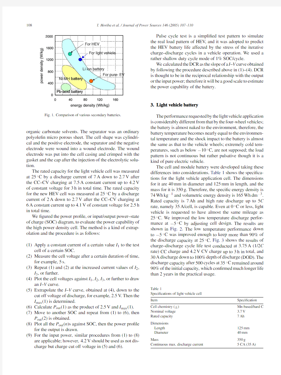
The cell and module battery were developed taking these differences into considerations.Table1shows the speci?ca-tions for the light vehicle application cell.The dimensions for it are40mm in diameter and125mm in length,and the mass for it is350g.Therefore,the speci?c energy density is 74Wh kg?1and volumetric energy density is165Wh dm?3. Rated capacity is7Ah and high rate discharge up to5C rate,namely35A/cell,is capable.Even at0?C or less,light vehicle is requested to have almost the same mileage as 25?C.We improved the low temperature discharge perfor-mance at?5?C by adjusting cell design.The results are shown in Fig.2.The low temperature performance down to?5?C was improved enough to keep more than90%of the discharge capacity at25?C.Fig.3shows the results of charge–discharge cycle life test conducted at3.75A(1/2C rate)CC charge and4.2V CV charge up to3h in total,and 30A discharge down to100%depth of discharge(DOD).The discharge capacity after500cycles at35?C remained around 90%of the initial capacity,which con?rmed much longer life than2years in the practical usage.
Table1
Speci?cations of light vehicle cell
Item Speci?cation Cell chemistry(±)Mn-based/hard C Nominal voltage 3.7V
Rated capacity7Ah Dimensions
Length125mm Diameter40mm
Mass350g Continuous max.discharge current5CA(35A)
T.Horiba et al./Journal of Power Sources 146(2005)107–110
109
Fig.2.Improvement of 30A discharge
performance.
Fig.3.Life cycle test of light vehicle cell.
Since the capacity,the power capability,the low temper-ature performance at ?5?C and the cycle life performance met the target for the light vehicle application,14-cell module battery for the application was designed,consisting of two-parallel cells connected in seven-series.The rating for it was 14Ah–26V ,the dimensions were 95mm in depth,370mm in length and 147mm in height,and the mass was 6kg.The light vehicle is a kind of electric scooters and already launched into the market by Yamaha Motor Co.[5].Although it is a small vehicle,it is surely classi?ed as a pure electric vehi-cle driven only by electric power with zero emission.We evaluated the merit for the electric scooter against a con-ventional ICE scooter with the life cycle assessment (LCA)method.Table 2shows the prerequisite for the LCA.One charge mileage for the electric vehicle is 32km and total mileage by the end of the life is 16,000km.Energy ef?ciency of charging is 85%.The ICE capacity is assumed to be 50ml,total mileage by the end of the life is also supposed to be
Table 2
Prerequisite for life cycle assessment Vehicle
Electric scooter (Li battery)ICE scooter (50ml engine)
One charge mileage:32km Average fuel economy:63km dm ?3Cycle life:500cycles Total mileage:16,000km Total mileage:16,000km Gasoline consumption:
16,000km/(63km dm ?3)=245dm 3
Charge energy:
26V ×14Ah ×500times Charge ef?ciency:85%
Drive speed:30km h ?1.
16,000km,the same as the electric scooter,and the average fuel economy is 63km dm ?3-gasoline.
The results for the LCA are shown in Table 3.Conse-quently,two-thirds of carbon dioxide,and 90%of SO x and NO x can be reduced by the introduction of the electric scooter.4.HEV battery
Table 4shows the comparison of the HEV cell speci?ca-tions between that developed in 2000called Gen 1and that developed recently called Gen 2.These two cells have the same dimensions and the same mass;however the capacity and power density of Gen 2are 1.5times of those of Gen 1.The big improvement shown in the table is supported by the some innovation of the positive electrode material and the electrolytic solution.Fig.4shows the power pro?le at 25?C based on 5s voltages.At 50%SOC,Gen 2cell has the
output
Fig.4.Power density pro?le of Gen 1and Gen 2cell.
Table 3
Result of life cycle assessment for light vehicle battery Vehicle
Energy consumption
Gas emission (g/veh.)CO 2
SO x NO x Electric scooter (Li battery)
Li battery:manuf.to disp.115,172176100Total mileage (16,000km)82,1764362Total
197,348219162ICE scooter (50ml engine)Driven by gasoline (16,000km)
599,186********Reduction rate of emission by electric scooter (%)
67
88
92
110
T.Horiba et al./Journal of Power Sources 146(2005)107–110
Table 4
High power Li ion cell:Gen 1and Gen 2Item
Gen 1Gen 2Dimensions (mm)?40×108?40×108Mass (g)
300300Nominal voltage (V) 3.6 3.6Capacity (Ah)
3.6 5.5Output power density (W kg ?1)a 20003000Input power density (W kg ?1)a
1500
2200
a
At 50%SOC and 25?
C.
Fig.5.Low temperature power pro?le at ?30?C.
power density of 3000W kg ?1,and the input power density of 2200W kg ?1.The power densities of the Gen 1cell were improved throughout the whole SOC span.
Fig.5shows the improvement in low temperature power capability at ?30?C.The Gen 2cell can deliver the output and input power over 50W/cell between 25%SOC and 60%SOC even at ?30?C.The large improvement was dependent on the material innovation in the positive electrode active material and the electrolytic solution.The power pro?le was calculated based on the same conditions as 25?C,namely the 5s pulse voltage and the cut off voltage of 2.5V .If the conditions were lowered to the shorter pulse and the lower cut off voltage,the power pro?le would be able to show much better values.
In Fig.6,the DCR changes in shallow duty pulse cycle test,1.5%for the Gen 1cell and 1%for Gen 2cell,at 50?
C
Fig.6.DCR change in light duty pulse cycle
test.
Fig.7.DCR change in storage life test.
is shown.The DCR for Gen 1cell increased to the doubling level after 300,000cycles,while that for the Gen 2showed less than 10%of increment after 250,000cycles.These results mean that the power fading in the pulse cycle test for the Gen 2cell is much reduced comparing to that for the Gen 1cell.Fig.7shows the DCR changes in the storage life test of a 50%SOC cell at 50?C.The DCR increment for the Gen 2cell is much less than that for the Gen 1cell,and the DCR after 150days storage is 3.4m ,suggesting the tendency of saturation.These excellent life test data are expected to support a longer calendar life in the practical use of the Gen 2lithium ion battery for the HEV application.Even for the Gen 1cell,the life longer than 5years or 100,000km life is expected in practical application [3,6],so the calendar life more than 10years,and may be 15years,is expected for the Gen 2cell based on the much suppressed DCR increase shown in Figs.6and 7.5.Conclusion
We have been developing Li ion batteries for industrial application,such as the automotive.Based on the last 10years R&D results,we have developed the Gen 2cell with high power and longer life.We expect that further application of the Li ion battery will develop in volume and variety in the near future.References
[1]T.Horiba,M.Kosei,T.Ishizu,T.Kojima,K.Takahashi,Y .Muranaka,
S.Nishimura,Proceedings of the 43th Battery Conference,Fukuoka,Japan,3A05,October,2002,pp.204–205.
[2]T.Horiba,K.Hironaka,M.Matsumura,et al.,J.Power Sources 97-98
(2001)719.
[3]T.Horiba,K.Hironaka,T.Matsumura,T.Kai,M.Koseki,Y .
Muranaka,J.Power Sources 119–121(2003)893.
[4]T.Horiba,K.Hironaka,T.Matsumura,T.Kai,M.Koseki,Y .
Muranaka,Proceedings of the 17th International Electric Vehicle Sym-posium,Montreal,Canada,4B-3,October 15–18,2000.
[5]T.Ono,Proceedings of the 20th International Electric Vehicle Sym-posium,Long Beach,CA,November 15–19,2003.
[6]M.Origuchi,N.Hirata,et al.,Proceedings of the 17th International
Electric Vehicle Symposium,Montreal,Canada,3B-3,October 15–18,2000.