
?Macroblock, Inc. 2010
Floor 6-4, No.18, Pu-Ting Rd., Hsinchu, Taiwan 30077, ROC.
With 16-bit PWM Control and Dot-Correction
Features
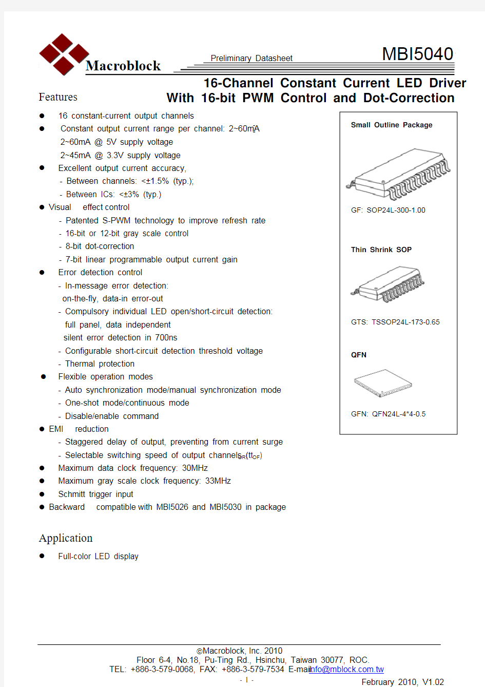
z 16 constant-current output channels
z
Constant output current range per channel: 2~60mA 2~60mA @ 5V supply voltage 2~45mA @ 3.3V supply voltage
z Excellent output current accuracy, - Between channels: <±1.5% (typ.); - Between ICs: <±3% (typ.)
z Visual effect control
- Patented S-PWM technology to improve refresh rate - 16-bit or 12-bit gray scale control - 8-bit dot-correction
- 7-bit linear programmable output current gain z
Error detection control - In-message error detection: on-the-fly, data-in error-out
- Compulsory individual LED open/short-circuit detection: full panel, data independent silent error detection in 700ns
- Configurable short-circuit detection threshold voltage - Thermal protection z
Flexible operation modes
- Auto synchronization mode/manual synchronization mode - One-shot mode/continuous mode - Disable/enable command z EMI reduction
- Staggered delay of output, preventing from current surge - Selectable switching speed of output channels (t OR , t OF ) z Maximum data clock frequency: 30MHz z Maximum gray scale clock frequency: 33MHz z
Schmitt trigger input
z Backward compatible with MBI5026 and MBI5030 in package
Application
z
Full-color LED display
Product Description
MBI5040 is a 16-channel constant current LED driver with selectable 16-/12-bit gray scale control and 8-bit dot correction. MBI5040 provides constant current ranging from 2mA to 60mA for each output channel. The output current can be set by an external resistor. MBI5040 adopts Share-I-O? technology to be backward compatible with MBI5026 and MBI5030 in package and to extend the functionality, such as in-message error detection, compulsory error detection, thermal protection, and current gain control in LED display systems.
With Scrambled-PWM (S-PWM) technology, MBI5040 enhances pulse width modulation by scrambling the “on” time into several “on” periods, so that MBI5040 is able to increase visual refresh rate and reduce flickers. In addition, MBI5040 provides 16-bit gray scale control to enrich the color of image, allowing to present video images with
65,536 gray scales. MBI5040 also provides 8-bit dot correction to individually calibrate the deviated brightness and color of LEDs. Moreover, the preset current of MBI5040 can be further adjusted by 128 steps for LED global brightness adjustment.
With in-message error detection, MBI5039 can detect individual LED for both open- and short-circuit errors
on-the-fly without extra components. Additionally, to enhance the system reliability, MBI5040 is built with thermal protection functions.
Function Ground terminal for control logic and current sink Serial-data input to the shift register
Clock input terminal used to shift data on rising edge and carries command information when Serial-data output to the SDI of next driver IC
Input terminal used to connect an external resistor for setting up output current for all output 14
13
151617183217
11232422212019MBI5040GFN
(3)
PWM Counting Mode
Users can set either continuous counting mode or one-shot counting mode by setting bit “C” of the configuration register.
For the continuous counting mode, the bit “C” is set to “0” (default). In the continuous counting mode, MBI5040 will continuously repeat the PWM cycles and turn on the output channels according to the image data until the next image data is correctly recognized.
For the one-shot counting mode, the bit “C” is set to “1”. In the one-shot counting mode, MBI5040 will run the PWM cycle for each image data one time, and then stop the output channels until the next image data is correctly recognized.
Error Detection Principle
MBI5040 provides two error detection functions: in-message error detection and compulsory error detection. Users can read the open-/short-circuit error reports, and thermal flag from SDO. For all the detection functions, “0” indicates error or abnormal state and “1” indicates normal state.
In-message Error Detection
Users can set the in-message error detection by bit “A” of configuration register. To enable the in-message error detection, the bit “A” is set to “1” (default). To disable the in-message error detection, the bit “A” is set to “0”.
The open-/short-circuit error will be reported only when output channels are turned on in 10 GCLKs, and the error reports will be put into the shift register after the gray scale data is latched.
Since the PWM output duty cycle of MBI5040 is the product of gray scale data and dot correction data. If the S-PWM algorithm is selected, the open-/short-circuit in-message error detection will be performed while the product of gray scale data and dot correction data is from 640 to 65,535 in the 16-bit gray scale mode or from 640 to 4,095 in the 12-bit gray scale mode. If the conventional PWM algorithm is selected, the open-/short-circuit error will be reported when the product of gray scale data and dot correction data is larger than 10.
MBI5040 will judge if the turn-on time is enough or not to deliver the error report. If the turned-on time is too short, MBI5040 will report normal state coded as “1”.
Error data (N)=error data(N-1) presents detection result.
It will be reset to 1 until the error data is read out.
t t t S
(nth detect