1/110
PRELIMINARY DATA
June 2004This is preliminary information on a new product now in development or undergoing evaluation. Details are subject to change without notice.
PSD813F2, PSD833F2
PSD834F2, PSD853F2, PSD854F2
Flash In-System Programmable (ISP)
Peripherals for 8-bit MCUs, 5V
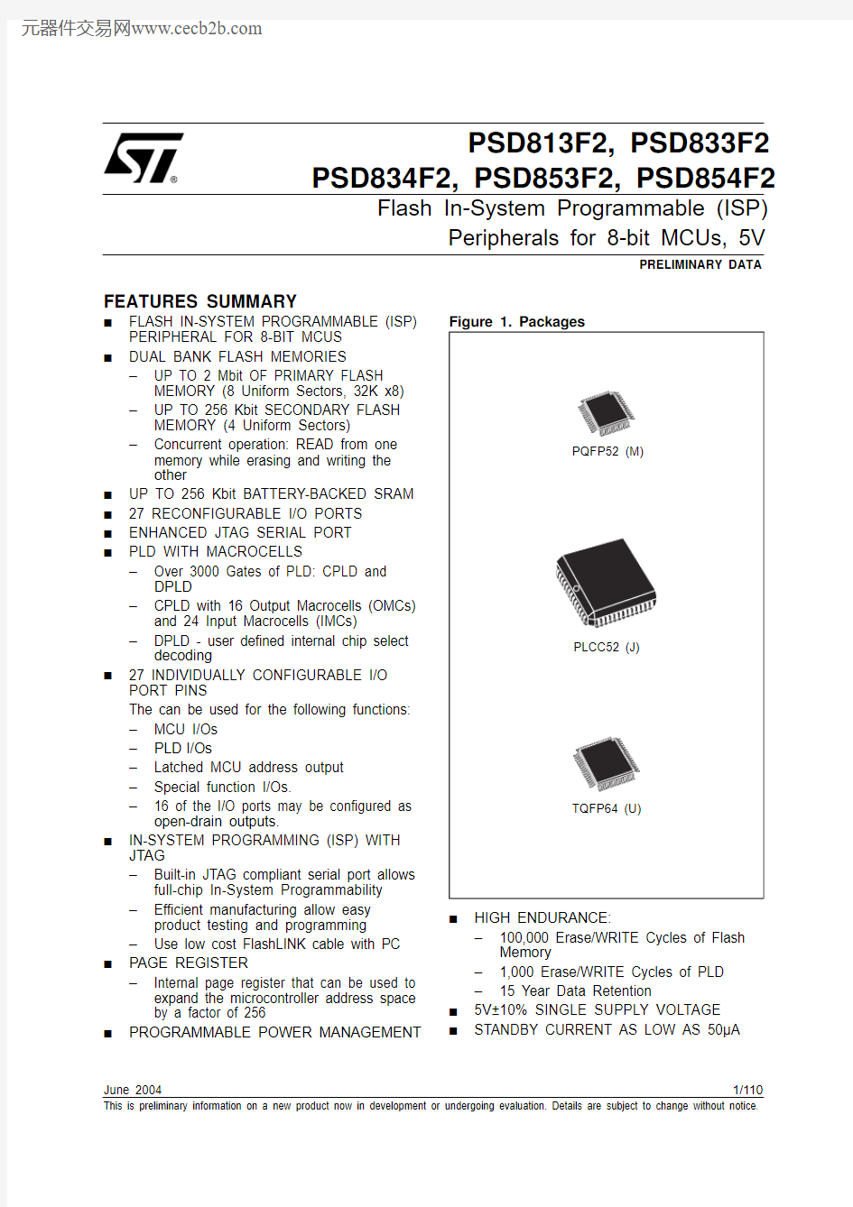
FEATURES SUMMARY ■FLASH IN-SYSTEM PROGRAMMABLE (ISP)
PERIPHERAL FOR 8-BIT MCUS ■
DUAL BANK FLASH MEMORIES
–UP TO 2 Mbit OF PRIMARY FLASH
MEMORY (8 Uniform Sectors, 32K x8)–UP TO 256 Kbit SECONDARY FLASH
MEMORY (4 Uniform Sectors)
–Concurrent operation: READ from one
memory while erasing and writing the other
■UP TO 256 Kbit BATTERY-BACKED SRAM ■27 RECONFIGURABLE I/O PORTS ■ENHANCED JTAG SERIAL PORT ■
PLD WITH MACROCELLS
–Over 3000 Gates of PLD: CPLD and
DPLD
–CPLD with 16 Output Macrocells (OMCs)
and 24 Input Macrocells (IMCs)
–DPLD - user defined internal chip select
decoding
■
27 INDIVIDUALLY CONFIGURABLE I/O PORT PINS
The can be used for the following functions:–MCU I/Os –PLD
I/Os
–Latched MCU address output –Special function I/Os.
–16 of the I/O ports may be configured as
open-drain outputs.
■
IN-SYSTEM PROGRAMMING (ISP) WITH JTAG
–Built-in JTAG compliant serial port allows
full-chip In-System Programmability –Efficient manufacturing allow easy
product testing and programming
–Use low cost FlashLINK cable with PC ■
PAGE REGISTER
–Internal page register that can be used to
expand the microcontroller address space by a factor of 256
■
PROGRAMMABLE POWER MANAGEMENT
■
HIGH ENDURANCE:
–100,000 Erase/WRITE Cycles of Flash
Memory
–1,000 Erase/WRITE Cycles of PLD –15 Year Data Retention
■5V±10% SINGLE SUPPLY VOLTAGE ■
STANDBY CURRENT AS LOW AS 50μA
PSD813F2, PSD833F2, PSD834F2, PSD853F2, PSD854F2
TABLE OF CONTENTS
FEATURES SUMMARY . . . . . . . . . . . . . . . . . . . . . . . . . . . . . . . . . . . . . . . . . . . . . . . . . . . . . . . . . . . . .1
SUMMARY DESCRIPTION. . . . . . . . . . . . . . . . . . . . . . . . . . . . . . . . . . . . . . . . . . . . . . . . . . . . . . . . . . .6 PIN DESCRIPTION. . . . . . . . . . . . . . . . . . . . . . . . . . . . . . . . . . . . . . . . . . . . . . . . . . . . . . . . . . . . . . . .10
PSD ARCHITECTURAL OVERVIEW. . . . . . . . . . . . . . . . . . . . . . . . . . . . . . . . . . . . . . . . . . . . . . . . . .15 Memory. . . . . . . . . . . . . . . . . . . . . . . . . . . . . . . . . . . . . . . . . . . . . . . . . . . . . . . . . . . . . . . . . . . . . .15 Page Register. . . . . . . . . . . . . . . . . . . . . . . . . . . . . . . . . . . . . . . . . . . . . . . . . . . . . . . . . . . . . . . . .15 PLDs. . . . . . . . . . . . . . . . . . . . . . . . . . . . . . . . . . . . . . . . . . . . . . . . . . . . . . . . . . . . . . . . . . . . . . . .15 I/O Ports . . . . . . . . . . . . . . . . . . . . . . . . . . . . . . . . . . . . . . . . . . . . . . . . . . . . . . . . . . . . . . . . . . . . .15 MCU Bus Interface. . . . . . . . . . . . . . . . . . . . . . . . . . . . . . . . . . . . . . . . . . . . . . . . . . . . . . . . . . . . .15 JTAG Port. . . . . . . . . . . . . . . . . . . . . . . . . . . . . . . . . . . . . . . . . . . . . . . . . . . . . . . . . . . . . . . . . . . .16 In-System Programming (ISP) . . . . . . . . . . . . . . . . . . . . . . . . . . . . . . . . . . . . . . . . . . . . . . . . . . .16 Power Management Unit (PMU). . . . . . . . . . . . . . . . . . . . . . . . . . . . . . . . . . . . . . . . . . . . . . . . . .16
DEVELOPMENT SYSTEM . . . . . . . . . . . . . . . . . . . . . . . . . . . . . . . . . . . . . . . . . . . . . . . . . . . . . . . . . .17 PSD Register Description and Address Offset. . . . . . . . . . . . . . . . . . . . . . . . . . . . . . . . . . . . . . . . .18
DETAILED OPERATION. . . . . . . . . . . . . . . . . . . . . . . . . . . . . . . . . . . . . . . . . . . . . . . . . . . . . . . . . . . .19
Memory Blocks . . . . . . . . . . . . . . . . . . . . . . . . . . . . . . . . . . . . . . . . . . . . . . . . . . . . . . . . . . . . . . .19 Primary Flash Memory and Secondary Flash memory Description. . . . . . . . . . . . . . . . . . . . .20 Memory Block Select Signals. . . . . . . . . . . . . . . . . . . . . . . . . . . . . . . . . . . . . . . . . . . . . . . . . . . .20
INSTRUCTIONS . . . . . . . . . . . . . . . . . . . . . . . . . . . . . . . . . . . . . . . . . . . . . . . . . . . . . . . . . . . . . . . . . .22
Power-up Mode . . . . . . . . . . . . . . . . . . . . . . . . . . . . . . . . . . . . . . . . . . . . . . . . . . . . . . . . . . . . . . .22 READ . . . . . . . . . . . . . . . . . . . . . . . . . . . . . . . . . . . . . . . . . . . . . . . . . . . . . . . . . . . . . . . . . . . . . . .22 Read Memory Contents . . . . . . . . . . . . . . . . . . . . . . . . . . . . . . . . . . . . . . . . . . . . . . . . . . . . . . . .22 Read Primary Flash Identifier. . . . . . . . . . . . . . . . . . . . . . . . . . . . . . . . . . . . . . . . . . . . . . . . . . . .22 Read Memory Sector Protection Status . . . . . . . . . . . . . . . . . . . . . . . . . . . . . . . . . . . . . . . . . . .22 Reading the Erase/Program Status Bits . . . . . . . . . . . . . . . . . . . . . . . . . . . . . . . . . . . . . . . . . . .23 Data Polling Flag (DQ7). . . . . . . . . . . . . . . . . . . . . . . . . . . . . . . . . . . . . . . . . . . . . . . . . . . . . . . . .24 Toggle Flag (DQ6) . . . . . . . . . . . . . . . . . . . . . . . . . . . . . . . . . . . . . . . . . . . . . . . . . . . . . . . . . . . . .24 Error Flag (DQ5). . . . . . . . . . . . . . . . . . . . . . . . . . . . . . . . . . . . . . . . . . . . . . . . . . . . . . . . . . . . . . .24 Erase Time-out Flag (DQ3). . . . . . . . . . . . . . . . . . . . . . . . . . . . . . . . . . . . . . . . . . . . . . . . . . . . . .24
PROGRAMMING FLASH MEMORY. . . . . . . . . . . . . . . . . . . . . . . . . . . . . . . . . . . . . . . . . . . . . . . . . . .25
Data Polling . . . . . . . . . . . . . . . . . . . . . . . . . . . . . . . . . . . . . . . . . . . . . . . . . . . . . . . . . . . . . . . . . .25 Data Toggle . . . . . . . . . . . . . . . . . . . . . . . . . . . . . . . . . . . . . . . . . . . . . . . . . . . . . . . . . . . . . . . . . .26 Unlock Bypass (PSD833F2x, PSD834F2x, PSD853F2x, PSD854F2x). . . . . . . . . . . . . . . . . . . .26
ERASING FLASH MEMORY . . . . . . . . . . . . . . . . . . . . . . . . . . . . . . . . . . . . . . . . . . . . . . . . . . . . . . . .27 Flash Bulk Erase . . . . . . . . . . . . . . . . . . . . . . . . . . . . . . . . . . . . . . . . . . . . . . . . . . . . . . . . . . . . . .27
2/110
PSD813F2, PSD833F2, PSD834F2, PSD853F2, PSD854F2
Flash Sector Erase . . . . . . . . . . . . . . . . . . . . . . . . . . . . . . . . . . . . . . . . . . . . . . . . . . . . . . . . . . . .27 Suspend Sector Erase . . . . . . . . . . . . . . . . . . . . . . . . . . . . . . . . . . . . . . . . . . . . . . . . . . . . . . . . .27 Resume Sector Erase . . . . . . . . . . . . . . . . . . . . . . . . . . . . . . . . . . . . . . . . . . . . . . . . . . . . . . . . . .27
SPECIFIC FEATURES . . . . . . . . . . . . . . . . . . . . . . . . . . . . . . . . . . . . . . . . . . . . . . . . . . . . . . . . . . . . .28
Flash Memory Sector Protect. . . . . . . . . . . . . . . . . . . . . . . . . . . . . . . . . . . . . . . . . . . . . . . . . . . .28 Reset Flash . . . . . . . . . . . . . . . . . . . . . . . . . . . . . . . . . . . . . . . . . . . . . . . . . . . . . . . . . . . . . . . . . .28 Reset (RESET) Signal (on the PSD83xF2 and PSD85xF2). . . . . . . . . . . . . . . . . . . . . . . . . . . . .28
SRAM . . . . . . . . . . . . . . . . . . . . . . . . . . . . . . . . . . . . . . . . . . . . . . . . . . . . . . . . . . . . . . . . . . . . . . . . . .29
SECTOR SELECT AND SRAM SELECT. . . . . . . . . . . . . . . . . . . . . . . . . . . . . . . . . . . . . . . . . . . . . . .30
Example . . . . . . . . . . . . . . . . . . . . . . . . . . . . . . . . . . . . . . . . . . . . . . . . . . . . . . . . . . . . . . . . . . . . .30 Memory Select Configuration for MCUs with Separate Program and Data Spaces . . . . . . . .30 Configuration Modes for MCUs with Separate Program and Data Spaces . . . . . . . . . . . . . . .30
PAGE REGISTER. . . . . . . . . . . . . . . . . . . . . . . . . . . . . . . . . . . . . . . . . . . . . . . . . . . . . . . . . . . . . . . . .32
PLDS. . . . . . . . . . . . . . . . . . . . . . . . . . . . . . . . . . . . . . . . . . . . . . . . . . . . . . . . . . . . . . . . . . . . . . . . . . .33
The Turbo Bit in PSD. . . . . . . . . . . . . . . . . . . . . . . . . . . . . . . . . . . . . . . . . . . . . . . . . . . . . . . . . . .33 Decode PLD (DPLD) . . . . . . . . . . . . . . . . . . . . . . . . . . . . . . . . . . . . . . . . . . . . . . . . . . . . . . . . . . .35 Complex PLD (CPLD) . . . . . . . . . . . . . . . . . . . . . . . . . . . . . . . . . . . . . . . . . . . . . . . . . . . . . . . . . .36 Output Macrocell (OMC). . . . . . . . . . . . . . . . . . . . . . . . . . . . . . . . . . . . . . . . . . . . . . . . . . . . . . . .37 Product Term Allocator. . . . . . . . . . . . . . . . . . . . . . . . . . . . . . . . . . . . . . . . . . . . . . . . . . . . . . . . .38 Loading and Reading the Output Macrocells (OMC) . . . . . . . . . . . . . . . . . . . . . . . . . . . . . . . . .38 The OMC Mask Register. . . . . . . . . . . . . . . . . . . . . . . . . . . . . . . . . . . . . . . . . . . . . . . . . . . . . . . .38 The Output Enable of the OMC . . . . . . . . . . . . . . . . . . . . . . . . . . . . . . . . . . . . . . . . . . . . . . . . . .38 Input Macrocells (IMC) . . . . . . . . . . . . . . . . . . . . . . . . . . . . . . . . . . . . . . . . . . . . . . . . . . . . . . . . .40
MCU BUS INTERFACE. . . . . . . . . . . . . . . . . . . . . . . . . . . . . . . . . . . . . . . . . . . . . . . . . . . . . . . . . . . . .43
PSD Interface to a Multiplexed 8-Bit Bus . . . . . . . . . . . . . . . . . . . . . . . . . . . . . . . . . . . . . . . . . .44 PSD Interface to a Non-Multiplexed 8-Bit Bus . . . . . . . . . . . . . . . . . . . . . . . . . . . . . . . . . . . . . .45 Data Byte Enable Reference. . . . . . . . . . . . . . . . . . . . . . . . . . . . . . . . . . . . . . . . . . . . . . . . . . . . .45 MCU Bus Interface Examples. . . . . . . . . . . . . . . . . . . . . . . . . . . . . . . . . . . . . . . . . . . . . . . . . . . .45 80C31 . . . . . . . . . . . . . . . . . . . . . . . . . . . . . . . . . . . . . . . . . . . . . . . . . . . . . . . . . . . . . . . . . . . . . . .46 80C251 . . . . . . . . . . . . . . . . . . . . . . . . . . . . . . . . . . . . . . . . . . . . . . . . . . . . . . . . . . . . . . . . . . . . . .47 80C51XA. . . . . . . . . . . . . . . . . . . . . . . . . . . . . . . . . . . . . . . . . . . . . . . . . . . . . . . . . . . . . . . . . . . . .49 68HC11. . . . . . . . . . . . . . . . . . . . . . . . . . . . . . . . . . . . . . . . . . . . . . . . . . . . . . . . . . . . . . . . . . . . . .50
I/O PORTS. . . . . . . . . . . . . . . . . . . . . . . . . . . . . . . . . . . . . . . . . . . . . . . . . . . . . . . . . . . . . . . . . . . . . . .51
General Port Architecture. . . . . . . . . . . . . . . . . . . . . . . . . . . . . . . . . . . . . . . . . . . . . . . . . . . . . . .51 Port Operating Modes. . . . . . . . . . . . . . . . . . . . . . . . . . . . . . . . . . . . . . . . . . . . . . . . . . . . . . . . . .51 MCU I/O Mode . . . . . . . . . . . . . . . . . . . . . . . . . . . . . . . . . . . . . . . . . . . . . . . . . . . . . . . . . . . . . . . .53 PLD I/O Mode. . . . . . . . . . . . . . . . . . . . . . . . . . . . . . . . . . . . . . . . . . . . . . . . . . . . . . . . . . . . . . . . .53 Address Out Mode. . . . . . . . . . . . . . . . . . . . . . . . . . . . . . . . . . . . . . . . . . . . . . . . . . . . . . . . . . . . .53 Address In Mode . . . . . . . . . . . . . . . . . . . . . . . . . . . . . . . . . . . . . . . . . . . . . . . . . . . . . . . . . . . . . .55
3/110
PSD813F2, PSD833F2, PSD834F2, PSD853F2, PSD854F2
Data Port Mode . . . . . . . . . . . . . . . . . . . . . . . . . . . . . . . . . . . . . . . . . . . . . . . . . . . . . . . . . . . . . . .55 Peripheral I/O Mode. . . . . . . . . . . . . . . . . . . . . . . . . . . . . . . . . . . . . . . . . . . . . . . . . . . . . . . . . . . .55 JTAG In-System Programming (ISP). . . . . . . . . . . . . . . . . . . . . . . . . . . . . . . . . . . . . . . . . . . . . .56 Port Configuration Registers (PCR) . . . . . . . . . . . . . . . . . . . . . . . . . . . . . . . . . . . . . . . . . . . . . .56 Control Register . . . . . . . . . . . . . . . . . . . . . . . . . . . . . . . . . . . . . . . . . . . . . . . . . . . . . . . . . . . . . .56 Direction Register . . . . . . . . . . . . . . . . . . . . . . . . . . . . . . . . . . . . . . . . . . . . . . . . . . . . . . . . . . . . .56 Drive Select Register. . . . . . . . . . . . . . . . . . . . . . . . . . . . . . . . . . . . . . . . . . . . . . . . . . . . . . . . . . .56 Port Data Registers. . . . . . . . . . . . . . . . . . . . . . . . . . . . . . . . . . . . . . . . . . . . . . . . . . . . . . . . . . . .57 Data In. . . . . . . . . . . . . . . . . . . . . . . . . . . . . . . . . . . . . . . . . . . . . . . . . . . . . . . . . . . . . . . . . . . . . . .57 Data Out Register . . . . . . . . . . . . . . . . . . . . . . . . . . . . . . . . . . . . . . . . . . . . . . . . . . . . . . . . . . . . .57 OMC Mask Register. . . . . . . . . . . . . . . . . . . . . . . . . . . . . . . . . . . . . . . . . . . . . . . . . . . . . . . . . . . .57 Input Macrocells (IMC) . . . . . . . . . . . . . . . . . . . . . . . . . . . . . . . . . . . . . . . . . . . . . . . . . . . . . . . . .58 Enable Out . . . . . . . . . . . . . . . . . . . . . . . . . . . . . . . . . . . . . . . . . . . . . . . . . . . . . . . . . . . . . . . . . . .58 Ports A and B – Functionality and Structure . . . . . . . . . . . . . . . . . . . . . . . . . . . . . . . . . . . . . . .58 Port C – Functionality and Structure. . . . . . . . . . . . . . . . . . . . . . . . . . . . . . . . . . . . . . . . . . . . . .59 Port D – Functionality and Structure. . . . . . . . . . . . . . . . . . . . . . . . . . . . . . . . . . . . . . . . . . . . . .60 External Chip Select . . . . . . . . . . . . . . . . . . . . . . . . . . . . . . . . . . . . . . . . . . . . . . . . . . . . . . . . . . .61
POWER MANAGEMENT . . . . . . . . . . . . . . . . . . . . . . . . . . . . . . . . . . . . . . . . . . . . . . . . . . . . . . . . . . .62
Automatic Power-down (APD) Unit and Power-down Mode . . . . . . . . . . . . . . . . . . . . . . . . . . .63 For Users of the HC11 (or compatible) . . . . . . . . . . . . . . . . . . . . . . . . . . . . . . . . . . . . . . . . . . . .64 Other Power Saving Options . . . . . . . . . . . . . . . . . . . . . . . . . . . . . . . . . . . . . . . . . . . . . . . . . . . .64 PLD Power Management. . . . . . . . . . . . . . . . . . . . . . . . . . . . . . . . . . . . . . . . . . . . . . . . . . . . . . . .64 PSD Chip Select Input (CSI, PD2) . . . . . . . . . . . . . . . . . . . . . . . . . . . . . . . . . . . . . . . . . . . . . . . .66 Input Clock. . . . . . . . . . . . . . . . . . . . . . . . . . . . . . . . . . . . . . . . . . . . . . . . . . . . . . . . . . . . . . . . . . .66 Input Control Signals . . . . . . . . . . . . . . . . . . . . . . . . . . . . . . . . . . . . . . . . . . . . . . . . . . . . . . . . . .66
RESET TIMING AND DEVICE STATUS AT RESET . . . . . . . . . . . . . . . . . . . . . . . . . . . . . . . . . . . . . .67
Power-Up Reset. . . . . . . . . . . . . . . . . . . . . . . . . . . . . . . . . . . . . . . . . . . . . . . . . . . . . . . . . . . . . . .67 Warm Reset . . . . . . . . . . . . . . . . . . . . . . . . . . . . . . . . . . . . . . . . . . . . . . . . . . . . . . . . . . . . . . . . . .67 I/O Pin, Register and PLD Status at Reset . . . . . . . . . . . . . . . . . . . . . . . . . . . . . . . . . . . . . . . . .67 Reset of Flash Memory Erase and Program Cycles (on the PSD834Fx) . . . . . . . . . . . . . . . . .67
PROGRAMMING IN-CIRCUIT USING THE JTAG SERIAL INTERFACE . . . . . . . . . . . . . . . . . . . . . .69
Standard JTAG Signals. . . . . . . . . . . . . . . . . . . . . . . . . . . . . . . . . . . . . . . . . . . . . . . . . . . . . . . . .69 JTAG Extensions. . . . . . . . . . . . . . . . . . . . . . . . . . . . . . . . . . . . . . . . . . . . . . . . . . . . . . . . . . . . . .70 Security and Flash memory Protection. . . . . . . . . . . . . . . . . . . . . . . . . . . . . . . . . . . . . . . . . . . .70
INITIAL DELIVERY STATE. . . . . . . . . . . . . . . . . . . . . . . . . . . . . . . . . . . . . . . . . . . . . . . . . . . . . . . . . .71 AC/DC PARAMETERS. . . . . . . . . . . . . . . . . . . . . . . . . . . . . . . . . . . . . . . . . . . . . . . . . . . . . . . . . . . . .72 MAXIMUM RATING. . . . . . . . . . . . . . . . . . . . . . . . . . . . . . . . . . . . . . . . . . . . . . . . . . . . . . . . . . . . . . . .75 DC AND AC PARAMETERS. . . . . . . . . . . . . . . . . . . . . . . . . . . . . . . . . . . . . . . . . . . . . . . . . . . . . . . . .76 PACKAGE MECHANICAL . . . . . . . . . . . . . . . . . . . . . . . . . . . . . . . . . . . . . . . . . . . . . . . . . . . . . . . . .100 4/110
PSD813F2, PSD833F2, PSD834F2, PSD853F2, PSD854F2 PART NUMBERING . . . . . . . . . . . . . . . . . . . . . . . . . . . . . . . . . . . . . . . . . . . . . . . . . . . . . . . . . . . . . .105 APPENDIX A.PQFP52 PIN ASSIGNMENTS . . . . . . . . . . . . . . . . . . . . . . . . . . . . . . . . . . . . . . . . . . .106 APPENDIX B.PLCC52 PIN ASSIGNMENTS . . . . . . . . . . . . . . . . . . . . . . . . . . . . . . . . . . . . . . . . . . .107 APPENDIX C.TQFP64 PIN ASSIGNMENTS . . . . . . . . . . . . . . . . . . . . . . . . . . . . . . . . . . . . . . . . . . .108 REVISION HISTORY. . . . . . . . . . . . . . . . . . . . . . . . . . . . . . . . . . . . . . . . . . . . . . . . . . . . . . . . . . . . . .109
5/110
PSD813F2, PSD833F2, PSD834F2, PSD853F2, PSD854F2
6/110
SUMMARY DESCRIPTION
The PSD8XXFX family of memory systems for mi-crocontrollers (MCUs) brings In-System-Program-mability (ISP) to Flash memory and programmable logic. The result is a simple and flexible solution for embedded designs. PSD devices combine many of the peripheral functions found in MCU based applications.
Table 1 summarizes all the devices in the PSD834F2, PSD853F2, PSD854F2.
The CPLD in the PSD devices features an opti-mized macrocell logic architecture. The PSD mac-rocell was created to address the unique requirements of embedded system designs. It al-lows direct connection between the system ad-dress/data bus, and the internal PSD registers, to simplify communication between the MCU and other supporting devices.
The PSD device includes a JTAG Serial Program-ming interface, to allow In-System Programming (ISP) of the entire device . This feature reduces de-velopment time, simplifies the manufacturing flow,and dramatically lowers the cost of field https://www.doczj.com/doc/1e10151548.html,ing ST’s special Fast-JTAG programming, a de-sign can be rapidly programmed into the PSD in as little as seven seconds.
The innovative PSD8XXFX family solves key problems faced by designers when managing dis-crete Flash memory devices, such as:
–First-time In-System Programming (ISP)–Complex address decoding
–Simultaneous read and write to the device.The JTAG Serial Interface block allows In-System Programming (ISP), and eliminates the need for an external Boot EPROM, or an external program-mer. To simplify Flash memory updates, program execution is performed from a secondary Flash memory while the primary Flash memory is being updated. This solution avoids the complicated hardware and software overhead necessary to im-plement IAP.
ST makes available a software development tool,PSDsoft Express, that generates ANSI-C compli-ant code for use with your target MCU. This code allows you to manipulate the non-volatile memory (NVM) within the PSD. Code examples are also provided for:
–Flash memory IAP via the UART of the host
MCU
–Memory paging to execute code across
several PSD memory pages
–Loading, reading, and manipulation of PSD
macrocells by the MCU.
Table 1. Product Range
Note: 1.All products support: JTAG serial ISP, MCU parallel ISP, ISP Flash memory, ISP CPLD, Security features, Power Management
Unit (PMU), Automatic Power-down (APD)
2.SRAM may be backed up using an external battery.
Part Number (1)
Primary Flash Memory (8 Sectors)
Secondary Flash Memory 4 Sectors)
SRAM (2)I/O Ports
Number of Macrocells Serial ISP JTAG/ISC Port Turbo Mode Input
Output PSD813F2 1 Mbit 256 Kbit 16 Kbit 272416yes yes PSD813F3 1 Mbit none 16 Kbit 272416yes yes PSD813F4 1 Mbit 256 Kbit none 272416yes yes PSD813F5 1 Mbit none none 272416yes yes PSD833F2 1 Mbit 256 Kbit 64 Kbit 272416yes yes PSD834F2 2 Mbit 256 Kbit 64 Kbit 272416yes yes PSD853F2 1 Mbit 256 Kbit 256 Kbit 272416yes yes PSD854F2
2 Mbit
256 Kbit
256 Kbit
27
24
16
yes
yes
PSD813F2, PSD833F2, PSD834F2, PSD853F2, PSD854F2
7/110
PSD813F2, PSD833F2, PSD834F2, PSD853F2, PSD854F2
8/110
PSD813F2, PSD833F2, PSD834F2, PSD853F2, PSD854F2
9/110
PSD813F2, PSD833F2, PSD834F2, PSD853F2, PSD854F2
10/110
PIN DESCRIPTION
Table 2. Pin Description (for the PLCC52 package - Note 1)
Pin Name
Pin
Type
Description
ADIO0-7
30-37
I/O
This is the lower Address/Data port. Connect your MCU address or address/data bus according to the following rules:
If your MCU has a multiplexed address/data bus where the data is multiplexed with the lower address bits, connect AD0-AD7 to this port.
If your MCU does not have a multiplexed address/data bus, or you are using an 80C251 in page mode, connect A0-A7 to this port.
If you are using an 80C51XA in burst mode, connect A4/D0 through A11/D7 to this port.ALE or AS latches the address. The PSD drives data out only if the READ signal is active and one of the PSD functional blocks was selected. The addresses on this port are passed to the PLDs.
ADIO8-15
39-46
I/O
This is the upper Address/Data port. Connect your MCU address or address/data bus according to the following rules:
If your MCU has a multiplexed address/data bus where the data is multiplexed with the lower address bits, connect A8-A15 to this port.
If your MCU does not have a multiplexed address/data bus, connect A8-A15 to this port.
If you are using an 80C251 in page mode, connect AD8-AD15 to this port.
If you are using an 80C51XA in burst mode, connect A12/D8 through A19/D15 to this port.
ALE or AS latches the address. The PSD drives data out only if the READ signal is active and one of the PSD functional blocks was selected. The addresses on this port are passed to the PLDs.
CNTL0
47
I
The following control signals can be connected to this port, based on your MCU:WR – active Low Write Strobe input.
R_W – active High READ/active Low write input.
This port is connected to the PLDs. Therefore, these signals can be used in decode and other logic equations.
CNTL1
50
I
The following control signals can be connected to this port, based on your MCU:RD – active Low Read Strobe input.E – E clock input.
DS – active Low Data Strobe input.
PSEN – connect PSEN to this port when it is being used as an active Low READ signal. For example, when the 80C251 outputs more than 16 address bits, PSEN is actually the READ signal.
This port is connected to the PLDs. Therefore, these signals can be used in decode and other logic equations.
CNTL249I
This port can be used to input the PSEN (Program Select Enable) signal from any MCU that uses this signal for code exclusively. If your MCU does not output a Program Select Enable signal, this port can be used as a generic input. This port is connected to the PLDs.
PSD813F2, PSD833F2, PSD834F2, PSD853F2, PSD854F2
Reset48I Resets I/O Ports, PLD macrocells and some of the Configuration Registers. Must be Low at Power-up.
PA0 PA1 PA2 PA3 PA4 PA5 PA6 PA729
28
27
25
24
23
22
21
I/O
These pins make up Port A. These port pins are configurable and can have the following
functions:
MCU I/O – write to or read from a standard output or input port.
CPLD macrocell (McellAB0-7) outputs.
Inputs to the PLDs.
Latched address outputs (see Table 6).
Address inputs. For example, PA0-3 could be used for A0-A3 when using an 80C51XA in
burst mode.
As the data bus inputs D0-D7 for non-multiplexed address/data bus MCUs.
D0/A16-D3/A19 in M37702M2 mode.
Peripheral I/O mode.
Note: PA0-PA3 can only output CMOS signals with an option for high slew rate. However,
PA4-PA7 can be configured as CMOS or Open Drain Outputs.
PB0 PB1 PB2 PB3 PB4 PB5 PB6 PB7
7
6
5
4
3
2
52
51
I/O
These pins make up Port B. These port pins are configurable and can have the following
functions:
MCU I/O – write to or read from a standard output or input port.
CPLD macrocell (McellAB0-7 or McellBC0-7) outputs.
Inputs to the PLDs.
Latched address outputs (see Table 6).
Note: PB0-PB3 can only output CMOS signals with an option for high slew rate.
However, PB4-PB7 can be configured as CMOS or Open Drain Outputs.
PC020I/O PC0 pin of Port C. This port pin can be configured to have the following functions: MCU I/O – write to or read from a standard output or input port.
CPLD macrocell (McellBC0) output.
Input to the PLDs.
TMS Input2 for the JTAG Serial Interface.
This pin can be configured as a CMOS or Open Drain output.
PC119I/O PC1 pin of Port C. This port pin can be configured to have the following functions: MCU I/O – write to or read from a standard output or input port.
CPLD macrocell (McellBC1) output.
Input to the PLDs.
TCK Input2 for the JTAG Serial Interface.
This pin can be configured as a CMOS or Open Drain output.
Pin Name Pin Type Description
11/110
PSD813F2, PSD833F2, PSD834F2, PSD853F2, PSD854F2
12/110
PC2
18
I/O
PC2 pin of Port C. This port pin can be configured to have the following functions:MCU I/O – write to or read from a standard output or input port.CPLD macrocell (McellBC2) output.
Input to the PLDs.
V STBY – SRAM stand-by voltage input for SRAM battery backup.This pin can be configured as a CMOS or Open Drain output.
PC3
17
I/O
PC3 pin of Port C. This port pin can be configured to have the following functions:MCU I/O – write to or read from a standard output or input port.CPLD macrocell (McellBC3) output.
Input to the PLDs.
TSTAT output 2 for the JTAG Serial Interface.
Ready/Busy output for parallel In-System Programming (ISP).This pin can be configured as a CMOS or Open Drain output.
PC4
14
I/O
PC4 pin of Port C. This port pin can be configured to have the following functions:MCU I/O – write to or read from a standard output or input port.CPLD macrocell (McellBC4) output.Input to the PLDs.
TERR output 2 for the JTAG Serial Interface.
Battery-on Indicator (V BATON ). Goes High when power is being drawn from the external battery.
This pin can be configured as a CMOS or Open Drain output.
PC5
13
I/O
PC5 pin of Port C. This port pin can be configured to have the following functions:MCU I/O – write to or read from a standard output or input port.CPLD macrocell (McellBC5) output.
Input to the PLDs.
TDI input 2 for the JTAG Serial Interface.
This pin can be configured as a CMOS or Open Drain output.
PC6
12
I/O
PC6 pin of Port C. This port pin can be configured to have the following functions:MCU I/O – write to or read from a standard output or input port.CPLD macrocell (McellBC6) output.
Input to the PLDs.
TDO output 2 for the JTAG Serial Interface.
This pin can be configured as a CMOS or Open Drain output.
Pin Name
Pin
Type
Description
13/110
PSD813F2, PSD833F2, PSD834F2, PSD853F2, PSD854F2
Note: 1.The pin numbers in this table are for the PLCC package only. See the package information from Table 74.,page 102 onwards, for
pin numbers on other package types.
2.These functions can be multiplexed with other functions.
PC7
11
I/O
PC7 pin of Port C. This port pin can be configured to have the following functions:MCU I/O – write to or read from a standard output or input port.CPLD macrocell (McellBC7) output.
Input to the PLDs.
DBE – active Low Data Byte Enable input from 68HC912 type MCUs.This pin can be configured as a CMOS or Open Drain output.
PD0
10
I/O
PD0 pin of Port D. This port pin can be configured to have the following functions:ALE/AS input latches address output from the MCU.
MCU I/O – write or read from a standard output or input port.Input to the PLDs.
CPLD output (External Chip Select).
PD1
9
I/O
PD1 pin of Port D. This port pin can be configured to have the following functions:MCU I/O – write to or read from a standard output or input port.Input to the PLDs.
CPLD output (External Chip Select).
CLKIN – clock input to the CPLD macrocells, the APD Unit’s Power-down counter, and the CPLD AND Array.
PD2
8
I/O
PD2 pin of Port D. This port pin can be configured to have the following functions:MCU I/O - write to or read from a standard output or input port.Input to the PLDs.
CPLD output (External Chip Select).
PSD Chip Select Input (CSI). When Low, the MCU can access the PSD memory and I/O. When High, the PSD memory blocks are disabled to conserve power.
V CC 15, 38Supply Voltage GND
1, 16, 26
Ground pins
Pin Name
Pin
Type
Description
PSD813F2, PSD833F2, PSD834F2, PSD853F2, PSD854F2
14/110
PSD813F2, PSD833F2, PSD834F2, PSD853F2, PSD854F2 PSD ARCHITECTURAL OVERVIEW
PSD devices contain several major functional blocks. Figure 5 shows the architecture of the PSD device family. The functions of each block are de-scribed briefly in the following sections. Many of the blocks perform multiple functions and are user configurable.
Memory
Each of the memory blocks is briefly discussed in the following paragraphs. A more detailed discus-sion can be found in the section entitled Memory Blocks,page19.
The 1 Mbit or 2 Mbit (128K x 8, or 256K x 8) Flash memory is the primary memory of the PSD. It is di-vided into 8 equally-sized sectors that are individ-ually selectable.
The optional 256 Kbit (32K x 8) secondary Flash memory is divided into 4 equally-sized sectors. Each sector is individually selectable.
The optional SRAM is intended for use as a scratch-pad memory or as an extension to the MCU SRAM. If an external battery is connected to Voltage Stand-by (V STBY, PC2), data is retained in the event of power failure.
Each sector of memory can be located in a differ-ent address space as defined by the user. The ac-cess times for all memory types includes the address latching and DPLD decoding time.
Page Register
The 8-bit Page Register expands the address range of the MCU by up to 256 times. The paged address can be used as part of the address space to access external memory and peripherals, or in-ternal memory and I/O. The Page Register can also be used to change the address mapping of sectors of the Flash memories into different mem-ory spaces for IAP.
PLDs
The device contains two PLDs, the Decode PLD (DPLD) and the Complex PLD (CPLD), as shown in Table 3, each optimized for a different function. The functional partitioning of the PLDs reduces power consumption, optimizes cost/performance, and eases design entry.The DPLD is used to decode addresses and to generate Sector Select signals for the PSD inter-nal memory and registers. The DPLD has combi-natorial outputs. The CPLD has 16 Output Macrocells (OMC) and 3 combinatorial outputs. The PSD also has 24 Input Macrocells (IMC) that can be configured as inputs to the PLDs. The PLDs receive their inputs from the PLD Input Bus and are differentiated by their output destinations, number of product terms, and macrocells.
The PLDs consume minimal power. The speed and power consumption of the PLD is controlled by the Turbo Bit in PMMR0 and other bits in the PMMR2. These registers are set by the MCU at run-time. There is a slight penalty to PLD propaga-tion time when invoking the power management features.
I/O Ports
The PSD has 27 individually configurable I/O pins distributed over the four ports (Port A, B, C, and D). Each I/O pin can be individually configured for different functions. Ports can be configured as standard MCU I/O ports, PLD I/O, or latched ad-dress outputs for MCUs using multiplexed ad-dress/data buses.
The JTAG pins can be enabled on Port C for In-System Programming (ISP).
Ports A and B can also be configured as a data port for a non-multiplexed bus.
MCU Bus Interface
PSD interfaces easily with most 8-bit MCUs that have either multiplexed or non-multiplexed ad-dress/data buses. The device is configured to re-spond to the MCU’s control signals, which are also used as inputs to the PLDs. For examples, please see the section entitled MCU Bus Interface Examples,page45.
Table 3. PLD I/O
Name Inputs Outputs
Product
Terms Decode PLD (DPLD)731742 Complex PLD (CPLD)7319140
15/110
PSD813F2, PSD833F2, PSD834F2, PSD853F2, PSD854F2
16/110
JTAG Port
In-System Programming (ISP) can be performed through the JTAG signals on Port C. This serial in-terface allows complete programming of the entire PSD device. A blank device can be completely programmed. The JTAG signals (TMS, TCK,TSTAT, TERR, TDI, TDO) can be multiplexed with other functions on Port C. Table 4 indicates the JTAG pin assignments.
In-System Programming (ISP)
Using the JTAG signals on Port C, the entire PSD device can be programmed or erased without the use of the MCU. The primary Flash memory can also be programmed in-system by the MCU exe-cuting the programming algorithms out of the sec-ondary memory, or SRAM. The secondary memory can be programmed the same way by ex-ecuting out of the primary Flash memory. The PLD or other PSD Configuration blocks can be pro-grammed through the JTAG port or a device pro-grammer. Table 5 indicates which programming methods can program different functional blocks of the PSD.
Power Management Unit (PMU)
The Power Management Unit (PMU) gives the user control of the power consumption on selected functional blocks based on system requirements.The PMU includes an Automatic Power-down (APD) Unit that turns off device functions during
MCU inactivity. The APD Unit has a Power-down mode that helps reduce power consumption.
The PSD also has some bits that are configured at run-time by the MCU to reduce power consump-tion of the CPLD. The Turbo Bit in PMMR0 can be reset to '0' and the CPLD latches its outputs and goes to sleep until the next transition on its inputs.Additionally, bits in PMMR2 can be set by the MCU to block signals from entering the CPLD to reduce power consumption. Please see the sec-tion entitled POWER MANAGEMENT,page 62 for more details.
Table 4. JTAG SIgnals on Port C
Table 5. Methods of Programming Different Functional Blocks of the PSD
Port C Pins
JTAG Signal
PC0 TMS PC1 TCK PC3 TSTAT PC4 TERR PC5 TDI PC6 TDO
Functional Block
JTAG Programming Device Programmer IAP
Primary Flash Memory Yes Yes Yes Secondary Flash Memory Yes Yes Yes PLD Array (DPLD and CPLD)Yes Yes No PSD Configuration
Yes
Yes
No
PSD813F2, PSD833F2, PSD834F2, PSD853F2, PSD854F2 DEVELOPMENT SYSTEM
The PSD8XXFX family is supported by PSDsoft Express, a Windows-based software development tool. A PSD design is quickly and easily produced in a point and click environment. The designer does not need to enter Hardware Description Lan-guage (HDL) equations, unless desired, to define PSD pin functions and memory map information. The general design flow is shown in Figure 6. PS-Dsoft Express is available from our web site (the address is given on the back page of this data sheet) or other distribution channels.PSDsoft Express directly supports two low cost device programmers form ST: PSDpro and FlashLINK (JTAG). Both of these programmers may be purchased through your local distributor/ representative, or directly from our web site using a credit card. The PSD is also supported by third party device programmers. See our web site for the current list.
17/110
PSD813F2, PSD833F2, PSD834F2, PSD853F2, PSD854F2
18/110
PSD REGISTER DESCRIPTION AND ADDRESS OFFSET
Table 6 shows the offset addresses to the PSD registers relative to the CSIOP base address. The CSIOP space is the 256 bytes of address that is al-located by the user to the internal PSD registers.
Table 7 provides brief descriptions of the registers in CSIOP space. The following section gives a more detailed description.
Table 6. I/O Port Latched Address Output Assignments (Note1)
Note: 1.See the section entitled I/O PORTS,page 51, on how to enable the Latched Address Output function.
2.N/A = Not Applicable
Table 7. Register Address Offset
Note: 1.Other registers that are not part of the I/O ports.
MCU
Port A
Port B
Port A (3:0) Port A (7:4) Port B (3:0) Port B (7:4)
8051XA (8-bit) N/A Address a7-a4Address a11-a8N/A
80C251 (page mode) N/A
N/A
Address a11-a8Address a15-a12All other 8-bit multiplexed Address a3-a0Address a7-a4Address a3-a0 Address a7-a48-bit non-multiplexed bus
N/A
N/A
Address a3-a0
Address a7-a4Register Name Port A Port B Port C Port D Other 1 Description
Data In 00 01 10
11
Reads Port pin as input, MCU I/O input mode Control 02 03 Selects mode between MCU I/O or Address Out Data Out 04 05 12 13 Stores data for output to Port pins, MCU I/O output mode
Direction 06 07 14 15 Configures Port pin as input or output
Drive Select 08 09 16 17
Configures Port pins as either CMOS or Open Drain on some pins, while selecting high slew rate on other pins.
Input Macrocell 0A 0B 18 Reads Input Macrocells
Enable Out 0C
0D
1A
1B Reads the status of the output enable to the I/O Port driver
Output Macrocells AB
20 20
READ – reads output of macrocells AB WRITE – loads macrocell flip-flops Output Macrocells BC
21 21 READ – reads output of macrocells BC WRITE – loads macrocell flip-flops Mask Macrocells AB 22
22 Blocks writing to the Output Macrocells AB
Mask Macrocells BC 23
23
Blocks writing to the Output Macrocells BC Primary Flash Protection C0 Read only – Primary Flash Sector Protection Secondary Flash memory Protection C2 Read only – PSD Security and Secondary Flash memory Sector Protection JTAG Enable C7 Enables JTAG Port
PMMR0 B0 Power Management Register 0PMMR2
B4
Power Management Register 2
Page E0 Page Register VM E2
Places PSD memory areas in Program and/or Data space on an individual basis.
PSD813F2, PSD833F2, PSD834F2, PSD853F2, PSD854F2 DETAILED OPERATION
As shown in Figure 5.,page14, the PSD consists of six major types of functional blocks:
■Memory Blocks
■PLD Blocks
■MCU Bus Interface
■I/O Ports
■Power Management Unit (PMU)
■JTAG Interface
The functions of each block are described in the following sections. Many of the blocks perform multiple functions, and are user configurable.Memory Blocks
The PSD has the following memory blocks:
–Primary Flash memory
–Optional Secondary Flash memory
–Optional SRAM
The Memory Select signals for these blocks origi-nate from the Decode PLD (DPLD) and are user-defined in PSDsoft Express.
Table 8. Memory Block Size and Organization
Primary Flash Memory Secondary Flash Memory SRAM
Sector Number Sector Size
(Bytes)
Sector Select
Signal
Sector Size
(Bytes)
Sector Select
Signal
SRAM Size
(Bytes)
SRAM Select
Signal
032K FS016K CSBOOT0256K RS0
132K FS116K CSBOOT1
232K FS216K CSBOOT2
332K FS316K CSBOOT3
432K FS4
532K FS5
632K FS6
732K FS7
Total512K8 Sectors64K 4 Sectors256K
19/110
PSD813F2, PSD833F2, PSD834F2, PSD853F2, PSD854F2
20/110
Primary Flash Memory and Secondary Flash memory Description
The primary Flash memory is divided evenly into eight equal sectors. The secondary Flash memory is divided into four equal sectors. Each sector of either memory block can be separately protected from Program and Erase cycles.
Flash memory may be erased on a sector-by-sec-tor basis. Flash sector erasure may be suspended while data is read from other sectors of the block and then resumed after reading.
During a Program or Erase cycle in Flash memory,the status can be output on Ready/Busy (PC3).This pin is set up using PSDsoft Express Configu-ration.
Memory Block Select Signals
The DPLD generates the Select signals for all the internal memory blocks (see the section entitled PLDS,page 33). Each of the eight sectors of the primary Flash memory has a Select signal (FS0-FS7) which can contain up to three product terms.Each of the four sectors of the secondary Flash memory has a Select signal (CSBOOT0-CSBOOT3) which can contain up to three product terms. Having three product terms for each Select signal allows a given sector to be mapped in differ-ent areas of system memory. When using a MCU with separate Program and Data space, these flexible Select signals allow dynamic re-mapping of sectors from one memory space to the other.Ready/Busy (PC3).This signal can be used to output the Ready/Busy status of the PSD. The out-put on Ready/Busy (PC3) is a 0 (Busy) when Flash memory is being written to, or when Flash memory is being erased. The output is a 1 (Ready) when no WRITE or Erase cycle is in progress.
Memory Operation.The primary Flash memory and secondary Flash memory are addressed through the MCU Bus Interface. The MCU can ac-cess these memories in one of two ways:
–The MCU can execute a typical bus WRITE or
READ operation just as it would if accessing a RAM or ROM device using standard bus cycles.
–The MCU can execute a specific instruction
that consists of several WRITE and READ operations. This involves writing specific data patterns to special addresses within the Flash memory to invoke an embedded algorithm. These instructions are summarized in Table 9.,page 21.
Typically, the MCU can read Flash memory using READ operations, just as it would read a ROM de-vice. However, Flash memory can only be altered using specific Erase and Program instructions. For example, the MCU cannot write a single byte di-rectly to Flash memory as it would write a byte to RAM. To program a byte into Flash memory, the MCU must execute a Program instruction, then test the status of the Program cycle. This status test is achieved by a READ operation or polling Ready/Busy (PC3).
Flash memory can also be read by using special instructions to retrieve particular Flash device in-formation (sector protect status and ID).