
Wide Supply Range, Rail-to-Rail
Rev. PrA
Information furnished by Analog Devices is believed to be accurate and reliable. However, no
responsibility is assumed by Analog Devices for its use, nor for any infringements of patents or other rights of third parties that may result from its use. Specifications subject to change without notice. No license is granted by implication or otherwise under any patent or patent rights of Analog Devices. T rademarks and registered trademarks are the property of their respective owners. One Technology Way, P.O. Box 9106, Norwood, MA 02062-9106, U.S.A. Tel: 781.329.4700 https://www.doczj.com/doc/188219853.html, Fax: 781.461.3113 ?2008 Analog Devices, Inc. All rights reserved.
FEATURES
Gain set with 1 external resistor Gain range: 1 to 1000
Input voltage goes to ground Input overdrive protection Very wide power supply range Dual supply: ±1.3 V to ±18 V Single supply: 2.6 V to 36 V Bandwidth (G = 1): 800 kHz CMRR (G = 1): 78 dB minimum Input noise: 22 nV/rt(Hz) Typical supply current: 350 μA SOIC-8 and MSOP-8 packages APPLICATIONS
Industrial process controls Bridge amplifiers
Medical instrumentation Portable data acquisition Multichannel systems
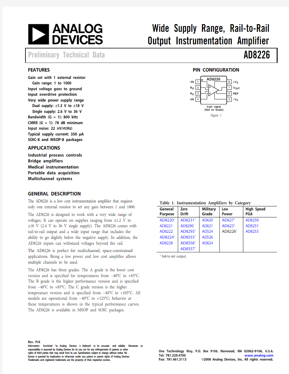
TOP VIEW
(Not to Scale)
7
3
6
-
1–IN
R G
R G
+IN
+V S
V OUT
REF
–V S
Figure 1.
GENERAL DESCRIPTION
The AD8226 is a low cost instrumentation amplifier that requires
only one external resistor to set any gain between 1 and 1000. The AD8226 is designed to work with a very wide range of voltages. It can operate on supplies ranging from ±1.2 V to
±18 V (2.4 V to 36 V single supply). The AD8226 comes with rail-to-rail output and a wide input range that includes the ability to go slightly below the negative supply. In addition, the AD8226 inputs can withstand voltages beyond the rail.
The AD8226 is perfect for multichannel, space-constrained applications. Being a low power and low cost amplifier allows multiple channels to be used.
The AD8226 has three grades. The A grade is the lower cost version and is specified for temperatures from ?40°C to +85°C. The B grade is the higher performance version and is specified from ?40°C to +85°C. The C grade version is the higher temperature version and is specified from ?40°C to +105°C. All models are operational from ?40°C to +125°C; behavior at these temperatures is shown in the typical performance curves. The AD8226 is available in MSOP and SOIC packages.
1Rail-to-rail output.
Rev. PrA | Page 2 of 16
TABLE OF CONTENTS
Features .............................................................................................. 1 Applications ....................................................................................... 1 Pin Configuration ............................................................................. 1 General Description ......................................................................... 1 Specifications ..................................................................................... 3 Absolute Maximum Ratings ............................................................ 7 Thermal Resistance ...................................................................... 7 ESD Caution .................................................................................. 7 Pin Configuration and Function Descriptions ............................. 8 Theory of Operation ........................................................................ 9 Architecture ...................................................................................9 Gain Selection ................................................................................9 Input Protection ............................................................................9 Reference Terminal .................................................................... 10 Input Voltage Range ................................................................... 10 Layout .......................................................................................... 10 Input Bias Current Return Path ............................................... 11 Radio Frequency Interference (RFI) ........................................ 11 Outline Dimensions ....................................................................... 12 Ordering Guide .. (13)
SPECIFICATIONS
+V S = +15 V, ?V S = ?15 V, V REF = 0 V, T A = 25°C, G = 1, R L = 10 kΩ, unless otherwise noted.
Rev. PrA | Page 3 of 16
Rev. PrA | Page 4 of 16
1 Does not include the effects of external resistor R G
2
Input voltage range of the AD8226 input stage. Input range depends on common mode voltage, differential voltage, gain, and reference voltage. See the Input Voltage Range section in the Theory of Operation for more information.
+V S = 2.7 V, –V S = 0 V, V REF = 0 V, T A = 25°C, G = 1, R L = 10 kΩ, unless otherwise noted.
Rev. PrA | Page 5 of 16
Rev. PrA | Page 6 of 16
1 Does not include the effects of external resistor R G
2
Input voltage range of the AD8226 input stage. Input range depends on common mode voltage, differential voltage, gain, and reference voltage. See the Input Voltage Range section in the Theory of Operation for more information.
Rev. PrA | Page 7 of 16
ABSOLUTE MAXIMUM RATINGS
1
Temperature range for specified performance is either ?40°C to +85°C or ?40°C to +105°C, depending on grade.
Stresses above those listed under Absolute Maximum Ratings may cause permanent damage to the device. This is a stress rating only; functional operation of the device at these or any other conditions above those indicated in the operational
section of this specification is not implied. Exposure to absolute maximum rating conditions for extended periods may affect device reliability. THERMAL RESISTANCE
θJA is specified for a device in free air.
Rev. PrA | Page 8 of 16
PIN CONFIGURATION AND FUNCTION DESCRIPTIONS
TOP VIEW (Not to Scale)
07036-002
–IN
R G R G +IN
+V S V OUT REF –V S
Figure 2. Pin Configuration
Rev. PrA | Page 9 of 16
THEORY OF OPERATION
07036-003
AMPLIFIER STAGE
GAIN STAGE
Figure 3. Simplified Schematic
ARCHITECTURE
The AD8226 is based on the classic three op amp topology. This topology has two stages: a preamplifier to provide differential amplification, followed by a difference amplifier to remove the common-mode voltage. Figure 3 shows a simplified schematic of the AD8226.
The first stage works as follows: in order to maintain a constant voltage across the Bias Resistor R B , Amplifier A1 must keep Node 3 a constant diode drop above the positive input voltage. Similarly, Amplifier A2 keeps Node 4 at a constant diode drop above the negative input voltage. Therefore a replica of the differential input voltage is placed across the gain setting resistor, R G . The current that flows across this resistance must also flow through the R1 and R2 resistors, creating a gained differential signal between the A2 and A1 outputs. Note that, in addition to a gained differential signal, the original common-mode signal, shifted a diode drop down, is also still present. The second stage is a difference amplifier, composed of A3 and four 50 k? resistors. The purpose of this stage is to remove the common-mode signal from the amplified differential signal. Because the input amplifiers employ a current feedback architecture, the gain-bandwidth product of the AD8226 increases with gain, resulting in a system that does not suffer from the expected bandwidth loss of voltage feedback architectures at higher gains.
The transfer function of the AD8226 is
V OUT = G (V IN+ ? V IN?) + V REF where
G
R G kΩ49.41+
=
GAIN SELECTION
Placing a resistor across the R G terminals sets the gain of the AD8226, which can be calculated by referring to Table 7 or by using the following gain equation:
1
kΩ49.4?=
G R G
The AD8226 defaults to G = 1 when no gain resistor is used. The tolerance and gain drift of the R G resistor should be added to the AD8226’s specifications to determine the total gain accuracy of the system. When the gain resistor is not used, gain error and gain drift are minimal.
INPUT PROTECTION
The input terminals of the AD8226 have input protection that allows the input voltage to go beyond the rails without damaging the part. Maximum voltage is –Vs+40 V and minimum voltage is +Vs-40 V . For example: with ±15 V
supplies, the part can withstand input voltages of ±25 V; with a 5 V single supply, maximum input voltage is 40 V and minimum input voltage is 35 V .
Rev. PrA | Page 10 of 16
REFERENCE TERMINAL
The output voltage of the AD8226 is developed with respect to the potential on the reference terminal. This is useful when the output signal needs to be offset to a precise midsupply level. For example, a voltage source can be tied to the REF pin to level-shift the output so that the AD8226 can drive a single-supply ADC. The REF pin is protected with ESD diodes and should not exceed either +V S or ?V S by more than 0.3 V .
For the best performance, source impedance to the REF
terminal should be kept below 2 ?. As shown in Figure 3, the reference terminal, REF, is at one end of a 50 kΩ resistor. Additional impedance at the REF terminal adds to this 50 kΩ resistor and results in amplification of the signal connected to the positive input. The amplification from the additional R REF can be computed by 2(50 kΩ + R REF )/100 kΩ + R REF . Only the positive signal path is amplified; the negative path is unaffected. This uneven amplification degrades CMRR.
INCORRECT
CORRECT
Figure 4. Driving the Reference Pin
INPUT VOLTAGE RANGE
The three op amp architecture of the AD8226 applies gain in the first stage before removing common-mode voltage in the difference amplifier stage. In addition, the input transistors in the first stage shift the common mode voltage up one diode drop (about 650 mV .) Therefore, internal nodes between the first and second stages (nodes 1 and 2 in Figure 3) experience a combination of gained signal, common-mode signal, and 650 mV . This combined signal can be limited by the voltage supplies even when the individual input and output signals are not. Figure XX through Figure XX show the allowable
common-mode input voltage ranges for various output voltages and supply voltages.
The following formulas can also be used to understand how the reference voltage (V REF ), common mode input voltage (V CM ), and differential input voltage (V DIFF ) interact. These two
formulas, along with the input range specifications in Table 1 and Table 3, set the boundaries where the part operates with best performance.
V 9.02
)
)((V 4.0?+<+<
??S CM DIFF S V V GAIN V V
V
V V V GAIN V S REF
CM DIFF .612
2
)
)((?+<++
The common-mode input range shifts upwards with temper-ature. At cold temperatures, the part requires an extra 200 mV of headroom from the positive supply, and operation near the negative supply has more margin. Conversely, hot temperatures require less headroom from the positive supply, but are the worst-case conditions for input voltages near the negative supply.
LAYOUT
To ensure optimum performance of the AD8226 at the PCB level, care must be taken in the design of the board layout. The AD8226 pins are arranged in a logical manner to aid in this task.
–IN R G R G S OUT S
+IN (Not to Scale)
07036-005
Figure 5. Pinout Diagram
Common-Mode Rejection Ratio over Frequency
Poor layout can cause some of the common-mode signals to be converted to differential signals before reaching the in-amp. Such conversions occur when one input path has a frequency response that is different from the other. To keep CMRR across frequency high, input source impedance and capacitance of each path should be closely matched. Additional source resistance in the input path (for example, for input protection) should be placed close to the in-amp inputs, which minimizes their interaction with parasitic capacitance from the PCB traces.
Parasitic capacitance at the gain setting pins can also affect CMRR over frequency. If the board design has a component at the gain setting pins (for example, a switch or jumper), the part should be chosen so that the parasitic capacitance is as small as possible.
Power Supplies
A stable dc voltage should be used to power the instrumenta-tion amplifier. Noise on the supply pins can adversely affect performance.
A 0.1 μF capacitor should be placed as close as possible to each supply pin. As shown in Figure 6, a 10 μF tantalum capacitor can be used farther away from the part. In most cases, it can be shared by other precision integrated circuits.
Rev. PrA | Page 11 of 16
+V
Figure 6. Supply Decoupling, REF, and Output Referred to Local Ground
References
The output voltage of the AD8226 is developed with respect to the potential on the reference terminal. Care should be taken to tie REF to the appropriate local ground.
INPUT BIAS CURRENT RETURN PATH
The input bias current of the AD8226 must have a return path to ground. When the source, such as a thermocouple, cannot provide a return current path, one should be created, as shown in Figure 7.
THERMOCOUPLE
–V
S
CAPACITIVELY COUPLED +V S
REF
C
C
–V S AD8226
TRANSFORMER
+V S
REF
–V
S
AD8226
INCORRECT
CAPACITIVELY COUPLED
f HIGH-PASS
THERMOCOUPLE
TRANSFORMER
–V S
CORRECT
07036-007
Figure 7. Creating an I BIAS Path
RADIO FREQUENCY INTERFERENCE (RFI)
RF rectification is often a problem when amplifiers are used in applications having strong RF signals. The disturbance can appear as a small dc offset voltage. High frequency signals can be filtered with a low-pass RC network placed at the input of the instru-mentation amplifier, as shown in Figure 8. The filter limits the input signal bandwidth, according to the following relationship:
FilterFrequency DIFF =
)
2(π21
C D C C R +
FilterFrequency CM = C
RC π21
where C D ≥ 10 C C .
+V 07036-008
Figure 8. RFI Suppression
C D affects the difference signal, and C C affects the common-mode signal. Values of R and C C should be chosen to minimize RFI. Mismatch between the R × C C at the positive input and the R × C C at the negative input degrades the CMRR of the AD8226. By using a value of C D one magnitude larger than C C , the effect of the mismatch is reduced, and performance is improved.
Rev. PrA | Page 12 of 16
OUTLINE DIMENSIONS
COMPLIANT TO JEDEC STANDARDS MO-187-AA
0.800.60
0.40
PLANE
0.10
Figure 9. 8-Lead Mini Small Outline Package [MSOP]
(RM-8)
Dimensions shown in millimeters
CONTROLLING DIMENSIONS ARE IN MILLIMETERS; INCH DIMENSIONS (IN PARENTHESES)ARE ROUNDED-OFF MILLIMETER EQUIVALENTS FOR REFERENCE ONLY AND ARE NOT APPROPRIATE FOR USE IN DESIGN.
COMPLIANT TO JEDEC STANDARDS MS-012-AA
012407-A
0.17 (0.0067)
0.25 (0.0098)0.10 (0.0040)COPLANARITY
0.10
Figure 10. 8-Lead Standard Small Outline Package [SOIC_N]
Narrow Body
(R-8)
Dimensions shown in millimeters and (inches)
1 Z = RoHS Compliant Part.
Rev. PrA | Page 13 of 16
NOTES
Rev. PrA | Page 14 of 16
NOTES
Rev. PrA | Page 15 of 16
AD8226
Preliminary Technical Data
Rev. PrA | Page 16 of 16
NOTES
?2008 An alog Devices, In c. All rights reserved. Trademarks an d registered trademarks are the property of their respective own ers.
PR07036-0-10/08(PrA)
元器件交易网https://www.doczj.com/doc/188219853.html,