ROS菜鸟系列1--实现共享上网,即内部网络多台机器通过ROS实现一起访问互联网的功能实现
前提条件:一台装有从网大公司购买的装好ROS电子盘及两张网卡的主机,通过显示器登录ROS(版本为3.30)
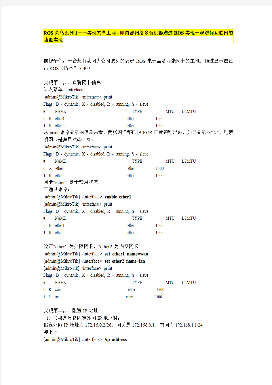
实现第一步:查看网卡信息
进入菜单:interface
[admin@MikroTik] /interface> print
Flags: D - dynamic, X - disabled, R - running, S - slave
# NAME TYPE MTU L2MTU
0 R ether1 ether 1500
1 R ether
2 ether 1500
从print命令显示的信息来看,两张网卡都已被ROS正常识别出来,如果显示的“X”,则表明网卡是禁用状态,如:
[admin@MikroTik] /interface> print
Flags: D - dynamic, X - disabled, R - running, S - slave
# NAME TYPE MTU L2MTU
0 X ether1 ether 1500
1 R ether
2 ether 1500
网卡“ether1”处于禁用状态
可通过命令:
[admin@MikroTik] /interface> enable ether1
[admin@MikroTik] /interface> print
Flags: D - dynamic, X - disabled, R - running, S - slave
# NAME TYPE MTU L2MTU
0 R ether1 ether 1500
1 R ether
2 ether 1500
设定“ether1”为外网网卡,“ether2”为内网网卡
[admin@MikroTik] /interface> set ether1 name=wan
[admin@MikroTik] /interface> set ether2 name=lan
[admin@MikroTik] /interface> print
Flags: D - dynamic, X - disabled, R - running, S - slave
# NAME TYPE MTU L2MTU
0 R wan ether 1500
1 R lan ether 1500
实现第二步:配置IP地址
1)如果是具备固定外网IP地址时:
假定外网IP地址为172.16.0.2/28,网关是172.168.0.1,内网为192.168.1.1/24
接上面:
[admin@MikroTik] /interface> /ip address
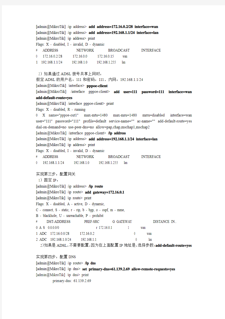
[admin@MikroTik] /ip address> add address=172.16.0.2/28 interface=wan
[admin@MikroTik] /ip address> add address=192.168.1.1/24 interface=lan
[admin@MikroTik] /ip address> print
Flags: X - disabled, I - invalid, D - dynamic
# ADDRESS NETWORK BROADCAST INTERFACE
0 172.16.0.2/28 172.16.0.0 172.16.0.15 wan
1 192.168.1.1/24 192.168.1.0 192.168.1.255 lan
2)如果通过ADSL拨号共享上网时:
假定ADSL的用户名:111和密码:111,内网:192.168.1.1/24
[admin@MikroTik] /interface> pppoe-client
[admin@MikroTik] /interface pppoe-client> add user=111 password=111 interface=wan add-default-route=yes
[admin@MikroTik] /interface pppoe-client> print
Flags: X - disabled, R - running
0 X name="pppoe-out1" max-mtu=1480 max-mru=1480 mrru=disabled interface=wan user="111" password="111" profile=default service-name="" ac-name="" add-default-route=yes dial-on-demand=no use-peer-dns=no allow=pap,chap,mschap1,mschap2
[admin@MikroTik] /interface pppoe-client> /ip address
[admin@MikroTik] /ip address> add address=192.168.1.1/24 interface=lan
[admin@MikroTik] /ip address> print
Flags: X - disabled, I - invalid, D - dynamic
# ADDRESS NETWORK BROADCAST INTERFACE
0 192.168.1.1/24 192.168.1.0 192.168.1.255 lan
实现第三步:配置网关
1)固定IP:
[admin@MikroTik] /ip address> /ip route
[admin@MikroTik] /ip route> add gateway=172.16.0.1
[admin@MikroTik] /ip route> print
Flags: X - disabled, A - active, D - dynamic,
C - connect, S - static, r - rip, b - bgp, o - ospf, m - mme,
B - blackhole, U - unreachable, P - prohibit
# DST-ADDRESS PREF-SRC G GATEW AY DISTANCE IN..
0 A S 0.0.0.0/0 r 172.16.0.1 1 wan
1 ADC 172.16.0.0/28 172.16.0.
2 0 wan
2 ADC 192.168.1.0/24 192.168.1.1 0 lan
2)如果是ADSL,不需要配置,因为在上面配置IP地址是,选择参数:add-default-route=yes
实现第四步:配置DNS
[admin@MikroTik] /ip route> /ip dns
[admin@MikroTik] /ip dns> set primary-dns=61.139.2.69 allow-remote-requests=yes [admin@MikroTik] /ip dns> print
primary-dns: 61.139.2.69
secondary-dns: 0.0.0.0
allow-remote-requests: yes
max-udp-packet-size: 512
cache-size: 2048KiB
cache-max-ttl: 1w
cache-used: 5KiB
参数allow-remote-requests=yes,意思是本地路由启用DNS功能,即:在内网机器上,配置DNS时可以直接使用网关地址作DNS服务器
实现第五步:隐藏,共享上网(NAT)
[admin@MikroTik] /ip dns> /ip firewall nat
[admin@MikroTik] /ip firewall nat> add chain=srcnat action=masquerade
[admin@MikroTik] /ip firewall nat> print
Flags: X - disabled, I - invalid, D - dynamic
0 chain=srcnat action=masquerade
以上五步即可完成利用ROS实现内网多台机器共享上网的功能,在后续的系列中,我们会在此基础上添加其他功能,利用ROS现实现其他目标明确的功能
如果是通过winbox连接到ROS的用户,以上所有的命令都可以在winbox中的主菜单中的:“new terminal”直接进行粘贴操作使用
ROS菜鸟系列2--构建PPPOE服务器
本教程是以“ROS菜鸟系列1--实现共享上网”为基础
利用ROS构建PPPOE服务器,通过对账号的管理实现对内网机器上网拨号授权,带宽限制等操作,
以上是本章节需要实现的功能。
实现第一步:创建地址池
所谓的地址池是用户拨号到服务器后,由服务器分配给客户一个拨号IP地址,通过这个IP 地址实现共享上网,假定提供的IP地址段为10.0.0.0/24
[admin@MikroTik] > ip pool
[admin@MikroTik] /ip pool> add name=pppoe ranges=10.0.0.2-10.0.0.254
[admin@MikroTik] /ip pool> print
# NAME RANGES
0 pppoe 10.0.0.2-10.0.0.254
创建一个名称为“pppoe”的地址池
实现第二步:建立用户类型
用户类型即为用户组,对用户先进行一个基于带宽的归类。
[admin@MikroTik] > ppp
[admin@MikroTik] /ppp> profile
Flags: * - default
0 * name="default" use-compression=default use-vj-compression=default
use-encryption=default only-one=default change-tcp-mss=yes
1 * name="default-encryption" use-compression=default
use-vj-compression=default use-encryption=yes only-one=default
change-tcp-mss=yes
[admin@MikroTik] /ppp profile>
在初始状态,有两个系统默认的属性类型:“default”和“default-encryption”,这两个是不允许作删除操作。
假定我们需要添加两个带宽分别为512K和1M的用户组
[admin@MikroTik] /ppp profile> add name=512K local-address=10.0.0.1 remote-address=pppoe dns-server=61.139.2.69 rate-limit=512K/512K only-one=yes idle-timeout=00:10:00
[admin@MikroTik] /ppp profile> add name=1M local-address=10.0.0.1 remote-address=pppoe dns-server=61.139.2.69 rate-limit=1M/1M only-one=yes idle-timeout=00:10:00
[admin@MikroTik] /ppp profile> print
Flags: * - default
0 * name="default" use-compression=default use-vj-compression=default
use-encryption=default only-one=default change-tcp-mss=yes
1 name="512K" local-address=10.0.0.1 remote-address=pppoe idle-timeout=10m
use-compression=default use-vj-compression=default
use-encryption=default only-one=yes change-tcp-mss=default
rate-limit=512K/512K dns-server=61.139.2.69
2 name="1M" local-address=10.0.0.1 remote-address=pppoe idle-timeout=10m
use-compression=default use-vj-compression=default
use-encryption=default only-one=yes change-tcp-mss=default
rate-limit=1M/1M dns-server=61.139.2.69
3 * name="default-encryption" use-compression=default
use-vj-compression=default use-encryption=yes only-one=default
change-tcp-mss=yes
解释一下部分参数的意思:local-address的意思是负责分配IP的服务器地址,作用相当于客户拨号后上网的网关,remote-address填写在第一步创建的地址池PPPOE,当客户拨号时,服务器会从地址池中拿一个空闲的IP分配给客户,rate-limit带宽限制值,only-one参数的作用是:是否限制同一时刻一个账号允许多个客户使用,idle-timeout参数是当用户无流量时,多长时间后,会自动从服务器断开。
实现第三步:建立账号信息
假定:添加一个512K的账号及一个1M的账号
[admin@MikroTik] /ppp profile> /
[admin@MikroTik] > ppp secret
[admin@MikroTik] /ppp secret> add name=111 password=111 profile=512K service=pppoe [admin@MikroTik] /ppp secret> add name=222 password=222 profile=1M service=pppoe
Flags: X - disabled
# NAME SERVICE CALLER-ID PASSWORD PROFILE REMOTE-ADDRESS
0 111 pppoe 111 512K
1 22
2 pppoe 222 1M
实现第四步:建立PPPOE服务器
[admin@MikroTik] /ppp secret>/
[admin@MikroTik] > interface pppoe-server server
[admin@MikroTik] /interface pppoe-server server> add service-name=pppoe interface=lan default-profile=default-encryption one-session-per-host=yes
[admin@MikroTik] /interface pppoe-server server> print
Flags: X - disabled
0 X service-name="pppoe" interface=lan max-mtu=1480 max-mru=1480 mrru=disabled
authentication=pap,chap,mschap1,mschap2 keepalive-timeout=10
one-session-per-host=yes max-sessions=0
default-profile=default-encryption
[admin@MikroTik] /interface pppoe-server server> enable 0
[admin@MikroTik] /interface pppoe-server server> print
Flags: X - disabled
0 service-name="pppoe" interface=lan max-mtu=1480 max-mru=1480 mrru=disabled
authentication=pap,chap,mschap1,mschap2 keepalive-timeout=10
one-session-per-host=yes max-sessions=0
default-profile=default-encryption
解释一下相关参数:
interface指定内网网卡,提供PPPOE服务器的网卡接口,max-mtu和max-mru最大传输单元和最大接收单元,如果有发现部分网站无法访问时,可以把这个参数修改小些,如1460等,one-session-per-host是否限制主机同一时刻的会话数,基于物理地址来限制,如果是yes,则表明新会话建立时,旧的会话会断开,与参数keepalive-timeout一起使用:“The default keepalive-timeout value of 10is OK in most cases. If you set it to 0, the router will not disconnect clients until they explicitly log out or the router is restarted. To resolve this problem, the one-session-per-host property can be used”
以上完成一个PPPOE服务器创建,
说些废话:如果想让客户全部通过PPPOE上网,不允许使用静态地址上网时,可以在ip-firewall-filter里面对内网配置的192.168.1.0/24的网段地址作drop操作,因为这个涉及到防火墙功能部分,故在后续中会有描述,本章节主要是说明如何构建PPPOE服务器
如果是通过winbox连接到ROS的用户,以上所有的命令都可以在winbox中的主菜单中的:“new terminal”直接进行粘贴操作使用
ROS菜鸟系列3--构建HOTSPOT认证服务器
本章节是以“ROS菜鸟系列1--实现共享上网”为基础,在此基础上添加HOTSPOT功能,构建出相应的认证服务器,HOTSPOT认证是以网页面认证的方式。
实现第一步:创建地址池
[admin@MikroTik] > ip pool
[admin@MikroTik] /ip pool> add name=hotspot ranges=192.168.1.100-192.168.1.200 [admin@MikroTik] /ip pool> print
# NAME RANGES
0 hotspot 192.168.1.100-192.168.1.200
创建地址池,HOTSPOT服务器会从地址池中分配IP地址给授权通过的客户,而不去理会客户电脑上所配置的IP地址。
实现第二步:添加用户组类型
基于带宽限制来添加用户组
假定分别添加一个512K和一个1M的用户组类型
[admin@MikroTik] /ip pool> ..
[admin@MikroTik] /ip> hotspot
[admin@MikroTik] /ip hotspot> user profile
[admin@MikroTik] /ip hotspot user profile> add name=512k address-pool=hotspot idle-timeout=00:10:00 keepalive-timeout=00:00:00 shared-users=1 rate-limit=512K/512K transparent-proxy=no
[admin@MikroTik] /ip hotspot user profile>add name=1M address-pool=hotspot idle-timeout=00:10:00 keepalive-timeout=00:00:00 shared-users=1 rate-limit=1M/1M transparent-proxy=no
[admin@MikroTik] /ip hotspot user profile> print
Flags: * - default
0 * name="default" idle-timeout=none keepalive-timeout=2m
status-autorefresh=1m shared-users=1 transparent-proxy=no
1 name="512k" address-pool=hotspot idle-timeout=10m keepalive-timeout=none
status-autorefresh=1m shared-users=1 rate-limit="512K/512K"
transparent-proxy=no
2 name="1M" address-pool=hotspot idle-timeout=10m keepalive-timeout=none
status-autorefresh=1m shared-users=1 rate-limit="1M/1M"
transparent-proxy=no
解释一下部分相关参数:shared-users意思是同一个账号允许同时通过授权电脑数量,transparent-proxy参数设定为YES时,用户的IP地址将启用代理的方式,通过IP地址查询得到的IP地址将显示成从地址池里面分配出来的IP地址,而不是真实的公网地址。
实现第三步:创建用户账号
假定分别创建一个512K和1M类型的用户账号
[admin@MikroTik] /ip hotspot user profile> ..
[admin@MikroTik] /ip hotspot user> add name=111 password=111 profile=512K
[admin@MikroTik] /ip hotspot user> add name=222 password=222 profile=1M
[admin@MikroTik] /ip hotspot user> print
Flags: X - disabled, D - dynamic
# SERVER NAME ADDRESS PROFILE UPTIME
0 111 512k 0s
1 22
2 1M 0s
实现第四步:创建HOTSPOT服务属性
[admin@MikroTik] /ip hotspot user> ..
[admin@MikroTik] /ip hotspot>
[admin@MikroTik] /ip hotspot> profile
[admin@MikroTik] /ip hotspot> add name=hotspot1 hotspot-address=192.168.1.1 html-directory=hotspot login-by=http-chap
[admin@MikroTik] /ip hotspot> print
Flags: * - default
0 * name="default" hotspot-address=0.0.0.0 dns-name="" html-directory=hotspot
rate-limit="" http-proxy=0.0.0.0:0 smtp-server=0.0.0.0
login-by=cookie,http-chap http-cookie-lifetime=3d split-user-domain=no
use-radius=no
1 name="hotspot1" hotspot-address=192.168.1.1 dns-name=""
html-directory=hotspot rate-limit="" http-proxy=0.0.0.0:0
smtp-server=0.0.0.0 login-by=http-chap split-user-domain=no
use-radius=no
解释一下相关的部分参数:login-by是指客户机的授权方式,有多种的授权方式(cookie http-chap http-pap https mac trial),http-chap是指利用网页面加密的授权方式,实现第五步:构建HOTSPOT服务
[admin@MikroTik] /ip hotspot> add name=hotspot interface=lan profile=hotspot1 disabled=no address-pool=hotspot
[admin@MikroTik] /ip hotspot> print
Flags: X - disabled, I - invalid, S - HTTPS
# NAME INTERFACE ADDRESS-POOL PROFILE IDLE-TIMEOUT 0 hotspot lan hotspot hotspot1 5m
由于有部分特殊用户需求,不需要通过授权就可以实现正常上网,假定:内网的一台机器使用192.168.1.200的IP地址,一开机就可以实现上网,不需要再通过输入用户账号。此时,可以利用HOTSPOT的ip-binding功能,
如:
[admin@MikroTik] /ip hotspot ip-binding> add address=192.168.1.200 to 192.168.1.200 mac-address=aa:bb:cc:dd:ee:ff type=bypassed
[admin@MikroTik] /ip hotspot ip-binding> print
Flags: X - disabled, P - bypassed, B - blocked
# MAC-ADDRESS ADDRESS TO-ADDRESS SERVER
0 P AA:BB:CC:DD:EE:FF 192.168.1.200 192.168.1.200
解释一下相关部分参数:mac-address参数为机器的MAC地址,填写后,则只有MAC地址和IP都对应的情况才允许,如果不填写MAC地址,则只要机器的IP相符合可任何机器都
可以实现正常上网,type=bypassed表明放行。
如果是通过winbox连接到ROS的用户,以上所有命令都可以在winbox中的主菜单:“new terminal”直接进行粘贴操作使用
ROS菜鸟系列4--简单路由策略实现
本章节是以“ROS菜鸟系列1”为基础,同时也可以应用到系列2,系列3上面,实现功能的完善,
路由策略:可以实现数据传输路径的优化,数据分流,线路备份,变相的实现带宽添加等。
本章节涉及的主要是较为简单的三种路由策略:1)基于端口分流的路由策略,2)基于目标地址3)基于源地址
只有在具备多条外网线路的情况下才涉及到分流,备份及优化的部分,因此假定引进第二条ISP线路:外网IP地址:10.10.10.2/28,网关10.10.10.1
实现第一步:添加IP地址
[admin@MikroTik] > ip address
[admin@MikroTik] /ip address> add address=10.10.10.2/28 interface=wan
[admin@MikroTik] /ip address> print
Flags: X - disabled, I - invalid, D - dynamic
# ADDRESS NETWORK BROADCAST INTERFACE
0 192.168.1.1/24 192.168.1.0 192.168.1.255 lan
1 172.16.0.2/28 172.16.0.0 172.16.0.15 wan
2 10.10.10.2/28 10.10.10.0 10.10.10.15 wan
实现第二步:标记数据包
1)基于端口标记
假定:对所有去访问目标80端口数据进行标记,同时客户可以根据自己的需要对其他端口进行标记,以达到符合的自己要求
[admin@MikroTik] > ip
[admin@MikroTik] /ip> firewall
[admin@MikroTik] /ip firewall> mangle
#添加连接标记规则
[admin@MikroTik] /ip firewall mangle> add chain=prerouting protocol=tcp dst-port=80 action=mark-connection new-connection-mark=web passthrough=yes
#添加路由标记规则
[admin@MikroTik] /ip firewall mangle> add chain=prerouting connection-mark=web action=mark-routing new-routing-mark=80 passthrough=no
[admin@MikroTik] /ip firewall mangle> print
Flags: X - disabled, I - invalid, D - dynamic
0 chain=prerouting action=mark-connection new-connection-mark=web
passthrough=yes protocol=tcp dst-port=80
1 chain=prerouting action=mark-routing new-routing-mark=80 passthrough=no connection-mark=web
以上完成对访问端口的标记,
# 假定所有的80端口数据将从第二条ISP线路走,而其他的数据从第一条ISP线路走[admin@MikroTik] /ip firewall mangle> /
[admin@MikroTik] ip route
[admin@MikroTik] /ip route> add gateway=10.10.10.2 routing-mark=80 check-gateway=ping admin@MikroTik] /ip route> print
Flags: X - disabled, A - active, D - dynamic,
C - connect, S - static, r - rip, b - bgp, o - ospf, m - mme,
B - blackhole, U - unreachable, P - prohibit
# DST-ADDRESS PREF-SRC GA TEW AY-STATE GATEW AY DISTANCE INTERFACE
0 A S 0.0.0.0/0 reachable 10.10.10.2 1 wan
1 A S 0.0.0.0/0 reachable 172.16.0.1 1 wan
2 ADC 10.10.10.0/28 10.10.10.2 0 wan
3 ADC 172.16.0.0/28 172.16.0.2 0 wan
4 ADC 192.168.1.0/24 192.168.1.1 0 lan
2)基于目标地址分流
假定访问目标地址为58.17.1.234的数据从第二条ISP线路走
第一种方法:此时可以直接在IP-ROUTE里面添加规则
如:
[admin@MikroTik] > ip
[admin@MikroTik] /ip> rout
[admin@MikroTik] /ip route> add dst-address=58.17.1.234 gateway=10.10.10.1 check-gateway=ping
admin@MikroTik] /ip route> print
Flags: X - disabled, A - active, D - dynamic,
C - connect, S - static, r - rip, b - bgp, o - ospf, m - mme,
B - blackhole, U - unreachable, P - prohibit
# DST-ADDRESS PREF-SRC G GATEW AY DISTANCE IN..
0 A S 0.0.0.0/0 r 172.16.0.1 1 wan
1 ADC 10.10.10.0/28 10.10.10.
2 0 wan
2 A S 58.17.1.234/32 r 10.10.10.1 1 wan
3ADC 172.16.0.0/28 172.16.0.2 0 wan
4ADC 192.168.1.0/24 192.168.1.1 0
第二种:可以先在IP--route--rule里面添加:
[admin@MikroTik] > ip rou
[admin@MikroTik] /ip route> rule
[admin@MikroTik] /ip route rule> add dst-address=58.17.1.234 Table=static action=lookup [admin@MikroTik] /ip route rule> print
Flags: X - disabled, I - inactive
0 dst-address=58.17.1.234/32 action=lookup table=static
然后在添加路由:
[admin@MikroTik] /ip route rule> ..
[admin@MikroTik] /ip route> add gateway=10.10.10.1 routing-mark=static check-gateway=ping [admin@MikroTik] /ip route> print
Flags: X - disabled, A - active, D - dynamic,
C - connect, S - static, r - rip, b - bgp, o - ospf, m - mme,
B - blackhole, U - unreachable, P - prohibit
# DST-ADDRESS PREF-SRC G GATEW AY DISTANCE IN..
0 A S 0.0.0.0/0 r 172.16.0.1 1 wan
1 A S 0.0.0.0/0 r 10.10.10.1 1 wan
2 ADC 10.10.10.0/28 10.10.10.2 0 wan
3 ADC 172.16.0.0/28 172.16.0.2 0 wan
4 ADC 192.168.1.0/24 192.168.1.1 0 lan
第三种:可以先在ip---firewall--address-list里面添加地址表
[admin@MikroTik] > ip firewall address-list
[admin@MikroTik] /ip firewall address-list> add list=static address=58.17.1.234
[admin@MikroTik] /ip firewall address-list> print
Flags: X - disabled, D - dynamic
# LIST ADDRESS
0 static 58.17.1.234
对目标地址标记:
[admin@MikroTik] /ip firewall address-list> ..
[admin@MikroTik] /ip firewall> mangle
[admin@MikroTik] /ip firewall mangle> add chain=prerouting dst-address-list=static action=mark-routing new-routing-mark=static passthrough=no
[admin@MikroTik] /ip firewall mangle> print
Flags: X - disabled, I - invalid, D - dynamic
0 chain=prerouting action=mark-routing new-routing-mark=static
passthrough=no dst-address-list=static
添加路由标记
[admin@MikroTik] /ip firewall mangle> /
[admin@MikroTik] > ip route
[admin@MikroTik] /ip route> add gateway=10.10.10.1 routing-mark=static check-gateway=ping [admin@MikroTik] /ip route> print
Flags: X - disabled, A - active, D - dynamic,
C - connect, S - static, r - rip, b - bgp, o - ospf, m - mme,
B - blackhole, U - unreachable, P - prohibit
# DST-ADDRESS PREF-SRC G GATEW AY DISTANCE IN..
0 A S 0.0.0.0/0 r 172.16.0.1 1 wan
1 A S 0.0.0.0/0 r 10.10.10.1 1 wan
2 ADC 10.10.10.0/28 10.10.10.2 0 wan
3 ADC 172.16.0.0/28 172.16.0.2 0 wan
4 ADC 192.168.1.0/24 192.168.1.1 0 lan
使用第一种方法,可以快速简单的添加定义每一条规则,但会使用整个ip-route里面显得很杂乱,不便于管理,第二种方法和第三种方法相对比较复杂些,但会让整个ip-route里面简单明了,便于管理
3)基于源地址策略
第一种:假定内网192.168.1.0/25走第一条ISP出口,内网192.168.1.128/25走第二条ISP 出口
#做标记
[admin@MikroTik] > ip firewall mangle
[admin@MikroTik] /ip firewall mangle> add chain=prerouting src-address=192.168.1.0/25 action=mark-routing new-routing-mark=GA
[admin@MikroTik] /ip firewall mangle> add chain=prerouting src-address=192.168.1.128/25 action=mark-routing new-routing-mark=GB
[admin@MikroTik] /ip firewall mangle> print
Flags: X - disabled, I - invalid, D - dynamic
0 chain=prerouting action=mark-routing new-routing-mark=GA passthrough=yes
src-address=192.168.1.0/25
1 chain=prerouting action=mark-routing new-routing-mark=GB passthrough=yes
src-address=192.168.1.128/25
#做路由策略
[admin@MikroTik] /ip firewall mangle> /
[admin@MikroTik] > ip
[admin@MikroTik] /ip> route
[admin@MikroTik] /ip route> add gateway=172.16.0.1 routing-mark=GA check-gateway=ping [admin@MikroTik] /ip route> add gateway=10.10.10.1 routing-mark=GB check-gateway=ping [admin@MikroTik] /ip route> print
Flags: X - disabled, A - active, D - dynamic,
C - connect, S - static, r - rip, b - bgp, o - ospf, m - mme,
B - blackhole, U - unreachable, P - prohibit
# DST-ADDRESS PREF-SRC G GATEW AY DISTANCE IN..
0 A S 0.0.0.0/0 R 10.10.10.1 1 wan
1 A S 0.0.0.0/0 r 172.16.0.1 1 wan
2 A S 0.0.0.0/0 R 172.16.0.1 1 wan
3 ADC 10.10.10.0/28 10.10.10.2 0 wan
4 ADC 172.16.0.0/28 172.16.0.2 0 wan
5 ADC 192.168.1.0/24 192.168.1.1 0 lan
这种方法,其实可以只用做192.168.1.128/25的内网IP段的标记即可,因为存在一条默认路由:1 A S 0.0.0.0/0 r 172.16.0.1 1 wan ,当192.168.1.0/25的Ip段,当找不到相应的标记路由时,路由器会最终选择默认路由进行转发出去。
第二种方法:(适用于内网非连续的IP地址段)
如假定:192.168.1.10,192.168.1.20-192.168.1.50,192.168.1.100-110的机器走第二条ISP 出口,其他走原第一条ISP出口
添加地址列表:
[admin@MikroTik] > ip
[admin@MikroTik] /ip> firewall address-list
[admin@MikroTik] /ip firewall address-list> add list=static address=192.168.1.10
[admin@MikroTik] /ip firewall address-list> add list=static address=192.168.1.20-192.168.1.50 [admin@MikroTik] /ip firewall address-list> add list=static address=192.168.1.100-192.168.1.110 [admin@MikroTik] /ip firewall address-list> print
Flags: X - disabled, D - dynamic
# LIST ADDRESS
0 static 192.168.1.10
1 static 192.168.1.20-192.168.1.50
2 static 192.168.1.100-192.168.1.110
标记源地址段的IP地址
[admin@MikroTik] /ip firewall address-list> ..
[admin@MikroTik] /ip firewall> mangle
[admin@MikroTik] /ip firewall mangle> add chain=prerouting src-address-list=static action=mark-routing new-routing-mark=static
[admin@MikroTik] /ip firewall mangle> print
Flags: X - disabled, I - invalid, D - dynamic
0 chain=prerouting action=mark-routing new-routing-mark=static
passthrough=yes src-address-list=static
添加路由策略标记
[admin@MikroTik] /ip firewall mangle> /
[admin@MikroTik] /ip route> add gateway=10.10.10.1 routing-mark=static check-gateway=ping [admin@MikroTik] /ip route> print
Flags: X - disabled, A - active, D - dynamic,
C - connect, S - static, r - rip, b - bgp, o - ospf, m - mme,
B - blackhole, U - unreachable, P - prohibit
# DST-ADDRESS PREF-SRC G GATEW AY DISTANCE IN..
0 A S 0.0.0.0/0 R 10.10.10.1 1 wan
1 A S 0.0.0.0/0 r 172.16.0.1 1 wan
2 ADC 10.10.10.0/28 10.10.10.2 0 wan
3 ADC 172.16.0.0/28 172.16.0.2 0 wan
4 ADC 192.168.1.0/24 192.168.1.1 0 lan
解释部分相关的参数:check-gateway:具备有两个选值ping和arp,意思是通过使用ping或者arp的功能对上层网关进行测试,当某条线路探测不通时,路由会把从该线路转发的数据自动跳转至其他备份的线路上面,当探测恢复时,线路会再自动跳转回来,从而实现线路的自动备份。
如果是通过winbox登录ROS时,以上的命令均可在主菜单的“new terminal”里面直接粘贴使用。
ROS菜鸟系列5--VPN简单应用
本章节以“ROS菜鸟系列1--实现共享上网”为基础,利用ROS的VPN功能可以实现共享内网资源、出口借线等
ROS的VPN整个构建过程与PPPOE构建过程类似。ROS较为简单常用的VPN有PPTP VPN 和L2TP VPN
一:构建VPN服务器
实现第一步:建立地址池
[admin@MikroTik] > ip pool
[admin@MikroTik] /ip pool> add name=vpn ranges=192.168.2.100-192.168.2.200
[admin@MikroTik] /ip pool> print
# NAME RANGES
0 vpn 192.168.2.100-192.168.2.200
实现第二步:建立用户组属性
分别添加一个512K和1M的用户组属性
[admin@MikroTik] /ip pool> /
[admin@MikroTik] > ppp profile
[admin@MikroTik] /ppp profile> add name=vpn512k local-address=192.168.2.1 remote-address=vpn dns-server=61.139.2.69 idle-timeout=00:10:00 rate-limit=512K/512K only-one=yes
[admin@MikroTik] /ppp profile> add name=vpn1M local-address=192.168.2.1 remote-address=vpn dns-server=61.139.2.69 idle-timeout=00:10:00 rate-limit=1M/1M only-one=yes
[admin@MikroTik] /ppp profile> print
Flags: * - default
0 * name="default" use-compression=default use-vj-compression=default
use-encryption=default only-one=default change-tcp-mss=yes
1 name="vpn512k" local-address=192.168.2.1 remote-address=vpn
idle-timeout=10m use-compression=default use-vj-compression=default
use-encryption=default only-one=yes change-tcp-mss=default
rate-limit=512K/512K dns-server=61.139.2.69
2 name="vpn1M" local-address=192.168.2.1 remote-address=vpn idle-timeout=10m
use-compression=default use-vj-compression=default
use-encryption=default only-one=yes change-tcp-mss=default
rate-limit=1M/1M dns-server=61.139.2.69
3 * name="default-encryption" use-compression=default
use-vj-compression=default use-encryption=yes only-one=default
change-tcp-mss=yes
实现第三步:添加用户账号信息
分别添加一个PPTP VPN和L2TP VPN的账号:
[admin@MikroTik] /ppp profile> ..
[admin@MikroTik] /ppp> secret
[admin@MikroTik] /ppp secret> add name=vpn1 password=vpn1 service=pptp profile=vpn512k
[admin@MikroTik] /ppp secret> add name=vpn2 password=vpn2 service=l2tp profile=vpn1M [admin@MikroTik] /ppp secret> print
Flags: X - disabled
# NAME SERVICE CALLER-ID PASSWORD PROFILE REMOTE-ADDRESS
0 vpn1 pptp vpn1 vpn512k
1 vpn
2 l2tp vpn2 vpn1M
实现第四步创建VPN的服务器
1)建立PPTP
[admin@MikroTik] /ppp secret> /
[admin@MikroTik] > interface pptp-server server
[admin@MikroTik] /interface pptp-server server> set enabled=yes keepalive-timeout=30 authentication=pap,chap,mschap1,mschap2
[admin@MikroTik] /interface pptp-server server> print
enabled: yes
max-mtu: 1460
max-mru: 1460
mrru: disabled
authentication: pap,chap,mschap1,mschap2
keepalive-timeout: 30
default-profile: default-encryption
解释一下部分相关参数:keepalive-timeout意思是服务器每隔多少会自动使用ICMP探测一下客户端
2)建立L2TP
[admin@MikroTik] > interface l2tp-server server
[admin@MikroTik] /interface l2tp-server server> set enabled=yes authentication=pap,chap,mschap1,mschap2
[admin@MikroTik] /interface l2tp-server server> print
enabled: yes
max-mtu: 1460
max-mru: 1460
mrru: disabled
authentication: pap,chap,mschap1,mschap2
default-profile: default-encryption
二:创建客户端:
利用ROS构建客户,主要是应用于把两个内部网络通过互联网相互连接,或者是借线做出口等功能
1)建立PPTP VPN客户端
[admin@MikroTik] > interface
[admin@MikroTik] /interface> pptp-client
[admin@MikroTik] /interface pptp-client> add name=pptpclient connect-to=11.11.11.11 user=vpn1 password=vpn1 disabled=no
[admin@MikroTik] /interface pptp-client> print
Flags: X - disabled, R - running
0 name="pptpclient" max-mtu=1460 max-mru=1460 mrru=disabled
connect-to=11.11.11.11 user="vpn1" password="vpn1"
profile=default-encryption add-default-route=no
allow=pap,chap,mschap1,mschap2
2)建立L2TP VPN客户端
[admin@MikroTik] /interface> l2tp-client
[admin@MikroTik] /interface l2tp-client> add name=l2tpclient connect-to=22.22.22.22 user=vpn2 password=vpn2 disabled=no
[admin@MikroTik] /interface l2tp-client> print
Flags: X - disabled, R - running
0 name="l2tpclient" max-mtu=1460 max-mru=1460 mrru=disabled
connect-to=22.22.22.22 user="vpn2" password="vpn2"
profile=default-encryption add-default-route=no
allow=pap,chap,mschap1,mschap2
解释一下相关的部分参数:
connect-to填写VPN服务器端的公网IP地址,user和password填写服务器分配的账号信息。
通过VPN客户端建立与服务器的VPN隧道后,根据具体需要,可以使用ROS路由策略的功能实现VPN借线,优化线路,或者让VPN客户端所在路由的内网与服务器端所在的路由内网通过隧道相互共享资源。
以上参数,如果是利用WINBOX登录路由时,可以在主菜单的“new terminal”中粘贴使用
ROS菜鸟系列6--防火墙简单应用
本章节以“ROS菜鸟系列1--实现共享上网”为基础,同时可以应用到系列2,系列3上,以完善其功能
ROS的filter规则等同于华为或者思科的ACL规则,安装好的ROS系统,在初始情况下,默认的防火规则有三种:input,output,forward三种链。简单说一下每一种的作用:input是指作用于所有去访问路由器本身的数据流,output是指作用于从路由器本身发出或者回应给其他访问的数据流,forward是指作用于通过路由器转发的数据流,主要是用于过滤内网用户与外网的数据交互。
举些简单的应用例子:
1)假定不允许从IP地址是192.168.1.100的机器登录路由器:
[admin@MikroTik] > ip
[admin@MikroTik] /ip> firewall filter
[admin@MikroTik] /ip firewall filter> add chain=input src-address=192.168.1.100 action=drop [admin@MikroTik] /ip firewall filter> print
Flags: X - disabled, I - invalid, D - dynamic
0 chain=input action=drop src-address=192.168.1.100
2)假定不允许路由器回应外网用户的PING探测:
[admin@MikroTik] /ip firewall filter>add chain=output protocol=icmp out-interface=wan icmp-options=0 action=drop
[admin@MikroTik] /ip firewall filter> print
Flags: X - disabled, I - invalid, D - dynamic
0 chain=input action=drop src-address=192.168.1.100
1 chain=output action=drop protocol=icmp out-interface=wan
icmp-options=0:0-255
解释相关的部分参数:protocol参数是指选择的协议,如TCP,UDP,ICMP等。icmp-options 意思是指ICMP的选项,代码0表示:echo replay。
3)假定禁止内网的机器使用192.168.1.200-192.168.1.220的IP地址访问外部网络
[admin@MikroTik] /ip firewall filter> add chain=forward src-address=192.168.1.200-192.168.1.220 action=drop
[admin@MikroTik] /ip firewall filter> print
Flags: X - disabled, I - invalid, D - dynamic
0 chain=input action=drop src-address=192.168.1.100
1 chain=output action=drop protocol=icmp out-interface=wan
icmp-options=0:0-255
2 chain=forward action=drop src-address=192.168.1.200-192.168.1.220
4)假定要实现防止外部网络使用TCP连接攻击路由器本身
[admin@MikroTik] /ip firewall filter>add chain=input protocol=tcp connection-limit=5,32 action=add-src-to-address-list address-list=black-address address-list-timeout=1d
[admin@MikroTik] /ip firewall filter> add chain=input src-address-list=black-address
action=drop
[admin@MikroTik] /ip firewall filter> print
Flags: X - disabled, I - invalid, D - dynamic
0 chain=input action=drop src-address=192.168.1.100
1 chain=output action=drop protocol=icmp out-interface=wan
icmp-options=0:0-255
2 chain=forward action=drop src-address=192.168.1.200-192.168.1.220
3 chain=input action=add-src-to-address-list protocol=tcp
address-list=black-address address-list-timeout=1d
connection-limit=5,32
4 chain=input action=drop src-address-list=black-address
以上的功能实现也可以利用filter与mangle相互配合使用:
[admin@MikroTik] /ip firewall filter> ..
[admin@MikroTik] /ip firewall> mangle
[admin@MikroTik] /ip firewall mangle> add chain=input protocol=tcp connection-limit=5,32 action=add-src-to-address-list address-list=black-address address-list-timeout=1d
[admin@MikroTik] /ip firewall mangle> print
Flags: X - disabled, I - invalid, D - dynamic
0 chain=input action=add-src-to-address-list protocol=tcp
address-list=black-address address-list-timeout=1d
connection-limit=5,32
[admin@MikroTik] /ip firewall mangle> ..
[admin@MikroTik] /ip firewall> filter
[admin@MikroTik] /ip firewall filter>add chain=input src-address-list=black-address action=drop
[admin@MikroTik] /ip firewall filter> print
Flags: X - disabled, I - invalid, D - dynamic
0 chain=input action=drop src-address-list=black-address
解释一下相关部分参数:action=add-src-to-address-list意思是把引起超过限制连接数的源地址提取出来,放入名称为black-address 的地址列表中。address-list-timeout参数的意思是放进black-address 地址列表中的IP地址在多久后释放出来。connection-limit参数是配置连接数的限制,connection-limit=5,32 参数中5代表5个连接数,32是指IP地址的子网掩码,意思是每一个来访问路由器的源地址同时只允许最多建立5个TCP连接数。
filter规则的默认执行顺序是从上往下的顺序执行,在执行的过程中可以对规则的action参数相关配置对执行顺序作跳转,如跳转到用户自定义的链执行完了会再返回原来的序列往下执行。
5)假定为了抑制ICMP包攻击,设定对转发和路由本身的对ICMP的请求及回应的ICMP包数据进行限定
[admin@MikroTik] /ip firewall filter>add chain=icmp protocol=icmp icmp-options=0 limit=5,32 action=accept
[admin@MikroTik] /ip firewall filter> add chain=icmp protocol=icmp
icmp-options=8 limit=5,32 action=accept
[admin@MikroTik] /ip firewall filter> print
Flags: X - disabled, I - invalid, D - dynamic
0 chain=icmp action=accept protocol=icmp icmp-options=0:0-255 limit=5,32
1 chain=icmp action=accept protocol=icmp icmp-options=8:0-255 limit=5,32
解释一下相关部分参数:chain=icmp意思是建立自定义的链ICMP
[admin@MikroTik] /ip firewall filter> add chain=input protocol=icmp action=jump jump-target=icmp
[admin@MikroTik] /ip firewall filter> add chain=forward protocol=icmp action=jump jump-target=icmp
[admin@MikroTik] /ip firewall filter> print
Flags: X - disabled, I - invalid, D - dynamic
0 chain=icmp action=accept protocol=icmp icmp-options=0:0-255 limit=5,32
1 chain=icmp action=accept protocol=icmp icmp-options=8:0-255 limit=5,32
2 chain=input action=jump jump-target=icmp protocol=icmp
3 chain=forward action=jump jump-target=icmp protocol=icmp
以上在filter规则里面的执行顺序如下:路由器先对数据流一一与0,1 这两个条匹配,不匹配时,往下执行。实行到第2条后,如果是对路由器本身进行作PING操作,则会跳转回0,1规则进行处理后,再往下执行第3条。
善用filter与mangle相互配合使用,可以实现许多功能强大的规则,为内网及路由本身提供完善的防火规则。
以上的规则,可以直接在“winbox”的“new terminal”中粘贴使用。
ROS菜鸟系列7--NAT的简单应用
NA T有两种方式:
一种是source nat或者叫srcnat,源地址NA T,意思是NAT路由把内部网络的私网地址转换成公网地址,以便实现对公网地址的共用
一种是destination nat或者叫dstnat,目标地址NAT,NA T路由会把访问的目标地址映射到内网的私网地址,以实现公网用户对内网资源的访问
简单的srcnat应用:
常用的srcnat应用主要有两种:
一:masquerade方式,masquerade方式会自动寻找路由设备的IP地址去替代IP数据包的源地址
[admin@MikroTik] > ip firewall nat
[admin@MikroTik] /ip firewall nat> add chain=srcnat action=masquerade
[admin@MikroTik] /ip firewall nat> print
Flags: X - disabled, I - invalid, D - dynamic
0 chain=srcnat action=masquerade
二:src-nat方式,src-nat方式会采用参数“to-addresses”中的特定值去替代IP数据包的源地址
假定:路由的外网地址172.16.0.2/24
[admin@MikroTik] /ip> firewall nat
[admin@MikroTik] /ip firewall nat> add chain=srcnat action=src-nat to-addresses=172.16.0.2 [admin@MikroTik] /ip firewall nat> print
Flags: X - disabled, I - invalid, D - dynamic
0 chain=srcnat action=src-nat to-addresses=172.16.0.2
三:dstnat:端口映射
假定内网有一台WEB服务器:192.168.2.100,需要对外提供WEB资源
[admin@MikroTik] > ip
[admin@MikroTik] /ip> firewall nat
[admin@MikroTik] /ip firewall nat> add chain=dstnat dst-address=172.16.0.2 proto
col=tcp dst-port=80 action=dst-nat to-addresses=192.168.2.100 to-ports=80
[admin@MikroTik] /ip firewall nat> print
Flags: X - disabled, I - invalid, D - dynamic
0 chain=dstnat action=dst-nat to-addresses=192.168.2.100 to-ports=80
protocol=tcp dst-address=172.16.0.2 dst-port=80
1 chain=srcnat action=masquerade
四:NA T功能举例:
实验结构:在外地机房存在一台ROS的有PPTP VPN服务器
实现功能:假定当从本地访问所需资源出现延时过高或者线路不稳定时,通过拨号连接至VPN服务后,从VPN服务器所在的ISP做中转,同时利用VPN服务器的NAT功能对不同的VPN授
权用户进行不同的访问限制,同时VPN服务器只具备单个网卡接口
本地路由器只需要实现正常共享上网(实现“ROS菜鸟系列1”功能)即可,
外地VPN服务器的构建:
实现第一步:先构建VPN服务器:
[admin@MikroTik] /interface> print
Flags: D - dynamic, X - disabled, R - running, S - slave
# NAME TYPE MTU
0 R ether1 ether 1500
[admin@MikroTik] /interface> set 0 name=wan
[admin@MikroTik] > interface print
Flags: D - dynamic, X - disabled, R - running, S - slave
# NAME TYPE MTU
0 R wan ether 1500
[admin@MikroTik] > ip address add address=211.2.123.42/28 interface=wan
[admin@MikroTik] > ip address print
Flags: X - disabled, I - invalid, D - dynamic
# ADDRESS NETWORK BROADCAST INTERFACE
0 211.2.123.42/28 211.2.123.32 211.2.123.47 wan
[admin@MikroTik] > ip route
[admin@MikroTik] /ip route> add gateway=211.2.123.33
[admin@MikroTik] /ip route> print
Flags: X - disabled, A - active, D - dynamic,
C - connect, S - static, r - rip, b - bgp, o - ospf, m - mme,
B - blackhole, U - unreachable, P - prohibit
# DST-ADDRESS PREF-SRC G GATEW AY DISTANCE IN..
0 A S 0.0.0.0/0 r 211.2.123.33 1 wan
1 ADC 211.2.123.32/28 211.2.123.4
2 0 wan
[admin@MikroTik] > ip pool
[admin@MikroTik] /ip pool> add name=limit ranges=192.168.100.2-192.168.100.254 [admin@MikroTik] /ip pool> add name=nolimit ranges=192.168.200.2-192.168.200.254 [admin@MikroTik] /ip pool> print
# NAME RANGES
0 limit 192.168.100.2-192.168.100.254
1 nolimit 192.168.200.2-192.168.200.254
增加地址池,为不同的授权用户动态分配不同的地址段
[admin@MikroTik] /ppp profile> add name=limitprofiles local-address=192.168.100.1 remote -address=limit dns-server=61.139.2.69 idle-timeout=00:10:00 rate-limit=512K/512K only-on e=yes
[admin@MikroTik] /ppp profile> add name=nolimitprofiles local-address=192.168.200.1 remo te-address=nolimit dns-server=61.139.2.69 idle-timeout=00:10:00 rate-limit=1M/1M only-on e=yes
[admin@MikroTik] /ppp profile> print
Flags: * - default