LM48511
March 22, 2012
3W, Ultra-Low EMI, Filterless, Mono, Class D Audio Power Amplifier with Spread Spectrum
General Description
The LM48511 integrates a boost converter with a high effi-ciency Class D audio power amplifier to provide 3W continu-ous power into an 8? speaker when operating from a 5V power supply. When operating from a 3V to 4V power supply,the LM48511 can be configured to drive 1 to 2.5W into an 8? load with less than 1% distortion (THD+N). The Class D amplifier features a low noise PWM architecture that elimi-nates the output filter, reducing external component count,board area consumption, system cost, and simplifying design.A selectable spread spectrum modulation scheme suppress-es RF emissions, further reducing the need for output filters.The LM48511’s switching regulator is a current-mode boost converter operating at a fixed frequency of 1MHz. Two se-lectable feedback networks allow the LM48511 regulator to dynamically switch between two different output voltages, im-proving efficiency by optimizing the amplifier’s supply voltage based on battery voltage and output power requirements.The LM48511 is designed for use in portable devices, such as GPS, mobile phones, and MP3 players. The high, 80%efficiency at 5V, extends battery life when compared to Boost-ed Class AB amplifiers. Independent regulator and amplifier shutdown controls optimize power savings by disabling the regulator when high output power is not required.
The gain of the LM48511 is set by external resistors, which allows independent gain control from multiple sources by summing the signals. Output short circuit and thermal over-load protection prevent the device from damage during fault conditions. Superior click and pop suppression eliminates au-dible transients during power-up and shutdown.
Key Specifications
■?Quiescent Power Supply Current
V DD = 3V V DD = 5V
9mA (typ)13.5mA (typ)■?P O at V DD = 5V, PV1 = 7.8V
R L = 8?, THD+N = 1%
3.0W (typ)■?P O at V DD = 3V, PV1 =
4.8V
R L = 8?, THD+N = 1%
1W (typ)■?P O at V DD = 5V, PV1 = 7.8V
R L = 4?, THD+N = 1%
5.4W (typ)■?Shutdown Current at V DD = 3V
0.01μA (typ)
Features
■3W Output into 8? at 5V with THD+N = 1%■Selectable spread spectrum mode reduces EMI ■80% Efficiency
■Independent Regulator and Amplifier Shutdown Controls ■Dynamically Selectable Regulator Output Voltages ■Filterless Class D ■ 3.0V – 5.5V operation ■Low Shutdown Current ■
Click and Pop Suppression
Applications
■GPS
■Portable media ■Cameras
■Mobile Phones ■
Handheld games
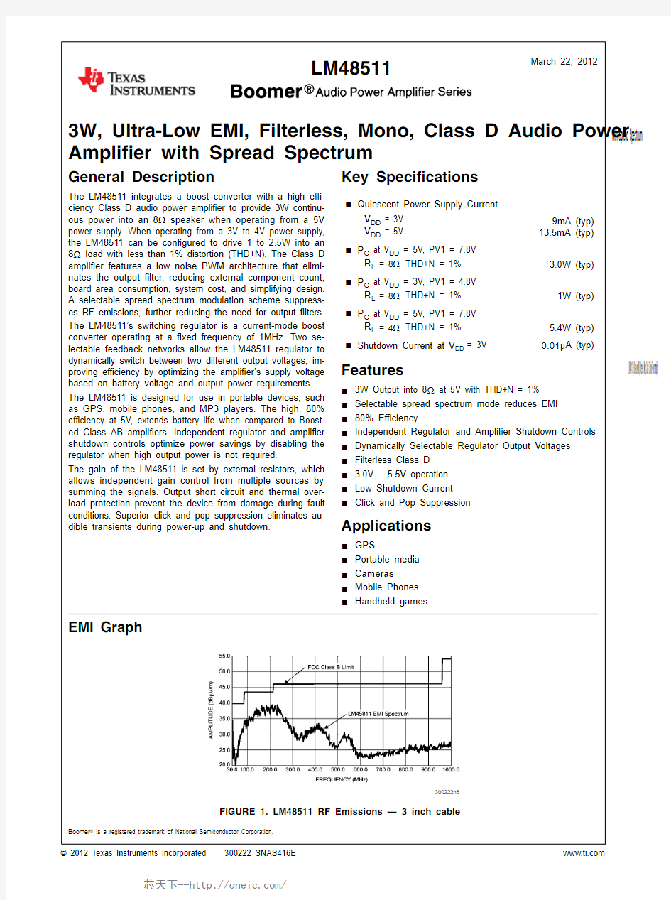
EMI Graph
300222h5
FIGURE 1. LM48511 RF Emissions — 3 inch cable
Boomer ? is a registered trademark of National Semiconductor Corporation.
? 2012 Texas Instruments Incorporated 300222 SNAS416E https://www.doczj.com/doc/0114298027.html,
LM48511 3W, Ultra-Low EMI, Filterless, Mono, Class D Audio Power Amplifier with Spread Spectrum
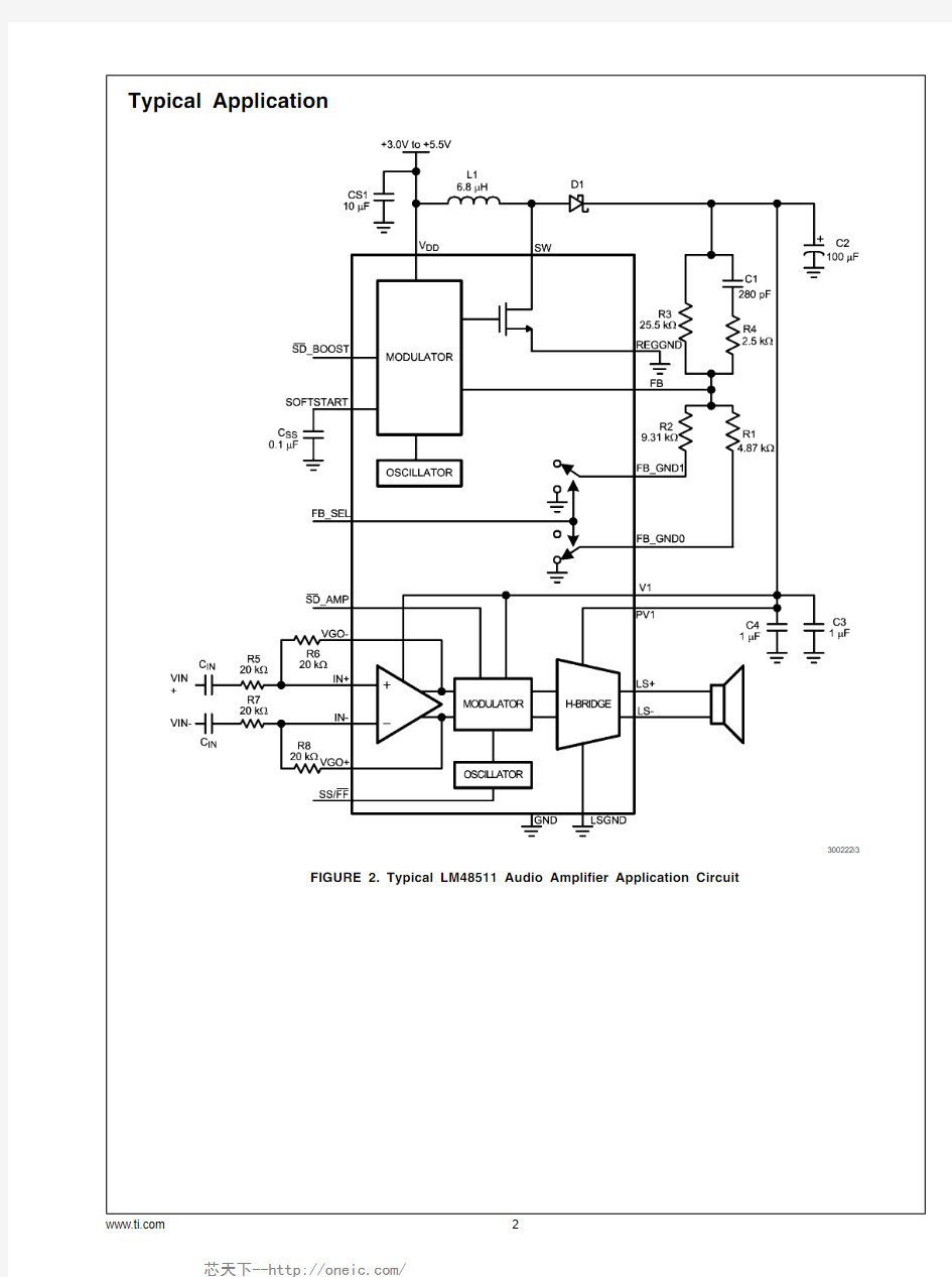
Typical Application
300222i3
FIGURE 2. Typical LM48511 Audio Amplifier Application Circuit
https://www.doczj.com/doc/0114298027.html, 2
L M 48511
Connection Diagrams
SQ Package
300222d4
Top View
Order Number LM48511SQ
See NS Package Number SQA24B
SQ Package Marking
300222d5
Top View
U — Wafer fab code
Z — Assembly plant
XY — 2 Digit date code
TT — Lot traceability
https://www.doczj.com/doc/0114298027.html, LM48511
Pin Descriptions
LLP-24 Pin
Name Function
1FB_SEL Regulator Feedback Select. Connect to VDD to select feedback network connected to FB_GND1. Connect to GND to select feedback network connected to FB_GND0.2,3SW Drain of the Internal FET Switch 4SOFTSTART Soft Start Capacitor
5SD_AMP Amplifier Active Low Shutdown. Connect to V DD for normal operation. Connect to GND to disable amplifier.
6SS/FF Modulation Mode Select. Connect to V DD for spread spectrum mode (SS). Connect to GND for fixed frequency mode (FF).7GND Signal Ground
8LS+Amplifier Non-Inverting Output 9, 11LSGND Amplifier H-Bridge Ground
10PV1Amplifier H-Bridge Power Supply. Connect to V1.12LS-Amplifier Inverting Output
13V1Amplifier Supply Voltage. Connect to PV114VG0+Amplifier Non-Inverting Gain Output 15IN-Amplifier Inverting Input 16IN+Amplifier Non-Inverting Input 17VG0–Amplifier Inverting Gain Output 18VDD Power Supply
19FB Regulator Feedback Input. Connect FB to an external resistive voltage divider to set the boost output voltage.20FB_GND1Ground return for R 3, R 1 resistor divider 21FB_GND0Ground return for R 3, R 2 resistor divider 22,23REGGND Power Ground (Booster)
24SD_BOOST
Regulator Active Low Shutdown. Connect to V DD for normal operation. Connect to GND to disable regulator.
DAP
To be soldered to board for enhanced thermal dissipation. Connect to GND plane.
https://www.doczj.com/doc/0114298027.html, 4
L M 48511
Absolute Maximum Ratings (Note 2, Note 2)
If Military/Aerospace specified devices are required, please contact the Texas Instruments Sales Office/ Distributors for availability and specifications.
Supply Voltage (V
DD , PV1, V
1
)9V
Storage Temperature?65°C to +150°C Input Voltage?0.3V to V DD + 0.3V Power Dissipation (Note 3)Internally limited ESD Susceptibility (Note 4)2000V ESD Susceptibility (Note 5)200V
Junction Temperature150°C Thermal Resistance
?θJC (SQ) 3.8°C/W θJA (SQ)32.8°C/W
Operating Ratings
Temperature Range
T
MIN
≤ T
A
≤ T
MAX
?40°C ≤ T A≤ +85°C
Supply Voltage (V
DD
) 3.0V ≤ V DD≤ 5.5V
Amplifier Voltage (PV
1
, V
1
) 4.8V ≤ PV1≤ 8.0V
Electrical Characteristics V
DD
= 5.0V (Note 1, Note 2, Note 10)
The following specifications apply for V
DD = 5.0V, PV
1
= 7.8V (continuos mode), A
V
= 2V/V, R
3
= 25.5k?, R
LS
= 4.87k?, R
L
=
8?, f = 1kHz, SS/FF = GND, unless otherwise specified. Limits apply for T A = 25°C.
Symbol Parameter Conditions
LM48511Units
(Limits) Typical
(Note 6)
Limit
(Note 7)
I DD Quiescent Power Supply Current
V
IN
= 0, R
LOAD
= ∞
Fixed Frequency Mode (FF)13.5mA (max)
Spread Spectrum Mode (SS)14.522mA (max)
I SD Shutdown Current
V
SD_BOOST
= V
SD_AMP
= SS =
FB_SEL = GND
0.111μA (max)
V
IH
Logic Voltage Input High 1.4V (min)
V
IL
Logic Voltage Input Low0.4V (max)
T WU Wake-up Time C
SS
= 0.1μF49ms
V
OS
Output Offset Voltage Note 120.013mV
P O Output Power
R
L
= 8?
f = 1kHz, BW = 22kHz
THD+N = 1%
FF
SS
3.0
3.0
2.6W (min)
W
THD+N = 10%
FF
SS
3.8
3.8
W
W
R
L
= 4?
f = 1kHz, BW = 22kHz
THD+N = 1%
FF
SS
5.4
5.4
W
W
THD+N = 10%
FF
SS
6.7
6.7
W
W
THD+N Total Harmonic Distortion + Noise P
O
= 2W, f = 1kHz, R
L
= 8?
FF
SS
0.03
0.03
%
%
P
O
= 3W, f = 1kHz, R
L
= 4?
FF
SS
0.04
0.05
%
% https://www.doczj.com/doc/0114298027.html,
LM48511
Symbol
Parameter
Conditions
LM48511
Units (Limits)
Typical (Note 6)
Limit (Note 7)
εOS
Output Noise
f = 20Hz to 20kHz
Inputs to AC GND, No weighting FF SS
3232
μV RMS μV RMS
f = 20Hz to 20kHz
Inputs to AC GND, A weighted FF SS
2222
μV RMS μV RMS
PSRR
Power Supply Rejection Ratio (Input Referred)
V RIPPLE = 200mV P-P Sine,f RIPPLE = = 217Hz, FF SS
8887dB dB
V RIPPLE = 200mV P-P Sine,f RIPPLE = = 1kHz, FF SS
8885
dB dB V RIPPLE = 200mV P-P Sine,f RIPPLE = = 10kHz, FF SS
7776
dB dB
CMRR Common Mode Rejection Ratio (Input Referred)V RIPPLE = 1V P-P , f RIPPLE = 217Hz 73 dB ηEfficiency
f = 1kHz, R L = 8?, P O = 1W
80 %V FB
Feedback Pin Reference Voltage
1.23
V
Electrical Characteristics V DD = 3.6V
(Note 1, Note 2, Note 10)
The following specifications apply for V DD = 3.6V, PV1 = 7V (continuous mode), A V = 2V/V, R 3 = 25.5k ?, R LS = 5.36k ?, R L = 8?,f = 1kHz, SS/FF = GND, unless otherwise specified. Limits apply for T A = 25°C.
Symbol
Parameter
Conditions
LM48511
Units (Limits)
Typical (Note 6)
Limit (Note 7)
I DD
Quiescent Power Supply Current
V IN = 0, R LOAD = ∞
Fixed Frequency Mode (FF)16mA (max)Spread Spectrum Mode (SS)
17.526.6mA (max)I SD Shutdown Current V SD_BOOST = V SD_AMP = SS =FB_SEL = GND
0.031μA (max)V IH Logic Voltage Input High 0.96 1.4V (min)V IL Logic Voltage Input Low 0.840.4V (min)T WU Wake-up Time C SS = 0.1μF 50 ms V OS
Output Offset Voltage
Note 12
0.04
mV
https://www.doczj.com/doc/0114298027.html, 6
L M 48511
Symbol Parameter Conditions
LM48511Units
(Limits) Typical
(Note 6)
Limit
(Note 7)
P O Output Power
R
L
= 8?, f = 1kHz, BW = 22kHz
THD+N = 1%
FF
SS
2.5
2.5
W
W
THD+N = 10%
FF
SS
3.0
3.0
W
W
R
L
= 4?, f = 1kHz, BW = 22kHz
THD+N = 1%
FF
SS
4.3
4.2
W
W
THD+N = 10%
FF
SS
5.4
5.3
W
W
THD+N Total Harmonic Distortion + Noise P
O
= 1.5W, f = 1kHz, R
L
= 8?
FF
SS
0.03
0.03
%
%
P
O
= 3W, f = 1kHz, R
L
= 4?
FF
SS
0.04
0.05
%
%
εOS Output Noise f = 20Hz to 20kHz
Inputs to AC GND, No weighting
FF
SS
35
36
μV
RMS
μV
RMS f = 20Hz to 20kHz
Inputs to AC GND, A weighted
FF
SS
25
26
μV
RMS
μV
RMS
PSRR Power Supply Rejection Ratio
(Input Referred)
V
RIPPLE
= 200mV
P-P
Sine,
f
RIPPLE =
= 217Hz
FF
SS
85
86
dB
dB
V
RIPPLE
= 200mV
P-P
Sine,
f
RIPPLE =
= 1kHz
FF
SS
87
86
dB
dB
V
RIPPLE
= 200mV
P-P
Sine,
f
RIPPLE =
= 10kHz
FF
SS
78
77
dB
dB
CMRR Common Mode Rejection Ratio
(Input Referred)
V
RIPPLE
= 1V
P-P
, f
RIPPLE
= 217Hz
73dB
ηEfficiency f = 1kHz, R L = 8?, P O = 1W77%
V
FB
Feedback Pin Reference Voltage 1.23V
https://www.doczj.com/doc/0114298027.html,
LM48511
Electrical Characteristics V DD = 3.0V
(Note 1, Note 2, Note 10)
The following specifications apply for V DD = 3.0V, PV1 = 4.8V (continuos mode), A V = 2V/V, R 3 = 25.5k ?, R LS = 9.31k ?, R L =8?, f = 1kHz, SS/FF = GND, unless otherwise specified. Limits apply for T A = 25°C.
Symbol
Parameter
Conditions
LM48511
Units (Limits)
Typical (Note 6)
Limit (Note 7)
I DD
Quiescent Power Supply Current
V IN = 0, R LOAD = ∞
Fixed Frequency Mode (FF)9 mA (max)Spread Spectrum Mode (SS)
9.5 mA (max)
I SD Shutdown Current V SD_BOOST = V SD_AMP = SS =FB_SEL = GND 0.011
μA V IH Logic Voltage Input High 0.91V (min)V IL Logic Voltage Input Low
0.79V T WU Wake-up Time C SS = 0.1μF 49 ms V OS
Output Offset Voltage
Note 12
0.04
mV
P O
Output Power
R L = 8?, f = 1kHz, BW = 22kHz THD+N = 1% FF SS
110.84
W (min)W THD+N = 10% FF SS
1.31.3
W W
R L = 4?, f = 1kHz, BW = 22kHz THD+N = 1% FF SS
1.81.8
W W THD+N = 10% FF SS
2.22.2
W W
THD+N Total Harmonic Distortion + Noise
P O = 500mW, f = 1kHz, R L = 8? FF SS
0.020.03
%%
P O = 500mW, f = 1kHz, R L = 4? FF SS
0.040.06
%%
εOS
Output Noise
f = 20Hz to 20kHz
Inputs to AC GND, No weighting FF SS
3535
μV RMS μV RMS
f = 20Hz to 20kHz
Inputs to AC GND, A weighted FF SS
2525
μV RMS μV RMS
https://www.doczj.com/doc/0114298027.html, 8
L M 48511
Symbol
Parameter
Conditions
LM48511
Units (Limits)
Typical (Note 6)
Limit (Note 7)
PSRR
Power Supply Rejection Ratio (Input Referred)
V RIPPLE = 200mV P-P Sine,f RIPPLE = = 217Hz FF SS
8989dB dB
V RIPPLE = 200mV P-P Sine,f RIPPLE = = 1kHz FF SS
8888
dB dB
V RIPPLE = 200mV P-P Sine,f RIPPLE = = 10kHz FF SS
7878 dB dB CMRR Common Mode Rejection Ratio (Input Referred)V RIPPLE = 1V P-P , f RIPPLE = 217Hz 71 dB ηEfficiency
f = 1kHz, R L = 8?, P O = 1W
75 %V FB
Feedback Pin Reference Voltage
1.23
V
Note 1:“Absolute Maximum Ratings” indicate limits beyond which damage to the device may occur, including inoperability and degradation of device reliability and/or performance. Functional operation of the device and/or non-degradation at the Absolute Maximum Ratings or other conditions beyond those indicated in the Recommended Operating Conditions is not implied. The Recommended Operating Conditions indicate conditions at which the device is functional and the device should not be operated beyond such conditions. All voltages are measured with respect to the ground pin, unless otherwise specified.
Note 2:The Electrical Characteristics tables list guaranteed specifications under the listed Recommended Operating Conditions except as otherwise modified or specified by the Electrical Characteristics Conditions and/or Notes. Typical specifications are estimations only and are not guaranteed.
Note 3:The maximum power dissipation must be derated at elevated temperatures and is dictated by T JMAX , θJ JA , and the ambient temperature, T A . The maximum allowable power dissipation is P DMAX = (T JMAX - T A ) / θJA or the number given in Absolute Maximum Ratings , whichever is lower. For the LM48511, see power derating curves for additional information.
Note 4:Human body model, applicable std. JESD22-A114C.Note 5:Machine model, applicable std. JESD22-A115-A.
Note 6:Typical values represent most likely parametric norms at T A = +25oC, and at the Recommended Operation Conditions at the time of product characterization and are not guaranteed.
Note 7:Datasheet min/max specification limits are guaranteed by test or statistical analysis.Note 8:Shutdown current is measured with components R1 and R2 removed.
Note 9:Feedback pin reference voltage is measured with the Audio Amplifier disconnected from the Boost converter (the Boost converter is unloaded).Note 10:R L is a resistive load in series with two inductors to simulate an actual speaker load for R L = 8?, the load is 15μH+8?+15μH. For R L = 4?, the load is 15μH+4?+15μH.
Note 11:Offset voltage is determined by: (I DD (with load) — I DD (no load)) x R L .
https://www.doczj.com/doc/0114298027.html,
LM48511
Typical Performance Characteristics
THD+N vs Frequency V DD = 5V, R L = 8?
P O = 2W, filter = 22kHz, PV 1 = 7.8V
300222g9THD+N vs Frequency V DD = 3.6V, R L = 8?
P O = 500mW, filter = 22kHz, PV 1 = 4.8V
300222g7
THD+N vs Frequency V DD = 3V, R L = 8?
P O = 1.5W, filter = 22kHz, PV 1 = 7V 300222g8THD+N vs Output Power
V DD = 5V, R L = 8?
P O = 1.5W, f = 1kHz, filter = 22kHz, PV 1 = 7.8V
300222h4
THD+N vs Output Power V DD = 3.6V, R L = 8?
f = 1kHz, filter = 22kHz, PV 1 = 7V 300222h1THD+N vs Output Power
V DD = 3V, R L = 8?
f = 1kHz, filter = 22kHz, PV 1 = 4.8V
300222h3
https://www.doczj.com/doc/0114298027.html, 10
L M 48511
THD+N vs Output Power
V DD = 3V, 3.6V, 5V, R
L
= 8?
f = 1kHz, filter = 22kHz, R
1
= 4.87k?, FF
300222i1
THD+N vs Output Power
V
DD
= 3.6V, R
L
= 8?
filter = 22kHz, PV
1
= 7.8V, PV
1
= 7V, PV
1
= 4.8V, FF
300222i0
Boost Amplifier vs Output Power
V DD = 5V, R
L
= 8?
f = 1kHz, PV
1
= 7.8V
300222f7Boost Amplifier vs Output Power
V
DD
= 3.6V, R
L
= 8?
f = 1kHz, PV
1
= 7V
300222f5
Boost Amplifier vs Output Power
V DD = 3V, R
L
= 8?
f = 1kHz, PV
1
= 4.8V
300222f6
PSRR vs Frequency
V
DD
= 5V, R
L
= 8?
V
RIPPLE
= 200mV
PP
, PV
1
= 7.8V
300222g3
https://www.doczj.com/doc/0114298027.html,
LM48511
PSRR vs Frequency V DD = 3.6V, R L = 8?
V RIPPLE = 200mV PP , PV 1 = 7V 300222g1PSRR vs Frequency V DD = 3V, R L = 8?
V RIPPLE = 200mV PP , PV 1 = 4.8V
300222g2
Supply Current vs Supply Voltage
PV 1 = 7.8V 300222g6
Supply Current vs Supply Voltage
PV 1 = 7V
300222g5
Supply Current vs Supply Voltage
PV 1 = 4.8V
300222g4
Power Dissipation vs Output Power
V DD = 5V, R L = 8?PV 1 = 7.8V, FF
300222g0
https://www.doczj.com/doc/0114298027.html, 12
L M 48511
Power Dissipation vs Output Power
V DD = 3.6V, R L = 8?
PV 1 = 7V, FF 300222f8Power Dissipation vs Output Power
V DD = 3V, R L = 8?PV 1 = 4.8V, FF
300222f9
Boost Converter Efficiency vs I LOAD(DC)
V DD = 5V, PV 1 = 7.8V 300222h8Boost Converter Efficiency vs I LOAD(DC)
V DD = 3.6V, PV 1 =7V
300222h6
Boost Converter Efficiency vs I LOAD(DC)
V DD = 3V, PV 1 = 4.8V
300222h7
https://www.doczj.com/doc/0114298027.html,
LM48511
Application Information
GENERAL AMPLIFIER FUNCTION
The LM48511 features a Class D audio power amplifier that utilizes a filterless modulation scheme, reducing external component count, conserving board space and reducing sys-tem cost. The outputs of the device transition from PV1 to GND with a 300kHz switching frequency. With no signal ap-plied, the outputs (V LS+ and V LS-) switch with a 50% duty cycle, in phase, causing the two outputs to cancel. This can-cellation results in no net voltage across the speaker, thus there is no current to the load in the idle state.
With the input signal applied, the duty cycle (pulse width) of the LM48511 outputs changes. For increasing output voltage,the duty cycle of V LS+ increases, while the duty cycle of V LS-decreases. For decreasing output voltages, the converse occurs. The difference between the two pulse widths yields the differential output voltage.
FIXED FREQUENCY
The LM48511 features two modulations schemes, a fixed fre-quency mode (FF) and a spread spectrum mode (SS). Select the fixed frequency mode by setting SS/FF = GND. In fixed frequency mode, the amplifier outputs switch at a constant 300kHz. In fixed frequency mode, the output spectrum con-sists of the fundamental and its associated harmonics (see Typical Performance Characteristics).
SPREAD SPECTRUM MODE
The logic selectable spread spectrum mode eliminates the need for output filters, ferrite beads or chokes. I n spread spectrum mode, the switching frequency varies randomly by 10% about a 330kHz center frequency, reducing the wide-band spectral contend, improving EMI emissions radiated by the speaker and associated cables and traces. Where a fixed frequency class D exhibits large amounts of spectral energy at multiples of the switching frequency, the spread spectrum architecture of the LM48511 spreads that energy over a larger bandwidth (See Typical Performance Characteristics). The cycle-to-cycle variation of the switching period does not affect the audio reproduction, efficiency, or PSRR. Set SS/FF =V DD for spread spectrum mode.
DIFFERENTIAL AMPLIFIER EXPLANATION
The LM48511 includes fully differential amplifier that features differential input and output stages. A differential amplifier amplifies the difference between the two input signals. Tradi-tional audio power amplifiers have typically offered only sin-gle-ended inputs resulting in a 6dB reduction in signal to noise ratio relative to differential inputs. The LM48511 also offers the possibility of DC input coupling which eliminates the two external AC coupling, DC blocking capacitors. The LM48511can be used, however, as a single ended input amplifier while still retaining it's fully differential benefits. In fact, completely unrelated signals may be placed on the input pins. The LM48511 simply amplifies the difference between the signals.A major benefit of a differential amplifier is the improved com-mon mode rejection ratio (CMRR) over single input amplifiers.The common-mode rejection characteristic of the differential amplifier reduces sensitivity to ground offset related noise in-jection, especially important in high noise applications.AUDIO AMPLIFIER POWER DISSIPATION AND EFFICIENCY
The major benefit of a Class D amplifier is increased efficiency versus a Class AB. The efficiency of the LM48511 is attributed to the region of operation of the transistors in the output stage.
The Class D output stage acts as current steering switches,consuming negligible amounts of power compared to their Class AB counterparts. Most of the power loss associated with the output stage is due to the IR loss of the MOSFET on-resistance, along with switching losses due to gate charge.REGULATOR POWER DISSIPATION
At higher duty cycles, the increased ON-time of the switch FET means the maximum output current will be determined by power dissipation within the LM48511 FET switch. The switch power dissipation from ON-time conduction is calcu-lated by:
P D(SWITCH) = DC x (I INDUCTOR(AVE))2 x R DS(ON) (W)(1)
where DC is the duty cycle.
SHUTDOWN FUNCTION
The LM48511 features independent amplifier and regulator shutdown controls, allowing each portion of the device to be disabled or enabled independently. SD_AMP controls the Class D amplifiers, while SD_BOOST controls the regulator.Driving either inputs low disables the corresponding portion of the device, and reducing supply current.
When the regulator is disabled, both FB_GND switches open,further reducing shutdown current by eliminating the current path to GND through the regulator feedback network. Without the GND switches, the feedback resistors as shown in Figure 1 would consume an additional 165μA from a 5V supply. With the regulator disabled, there is still a current path from V DD ,through the inductor and diode, to the amplifier power supply.This allows the amplifier to operate even when the regulator is disabled. The voltage at PV1 and V1 will be:
(V DD - [V D + (I L x DCR)]
(2)
Where V D is the forward voltage of the Schottky diode, I L is the current through the inductor, and DCR is the DC resis-tance of the inductor. Additionally, when the regulator is dis-abled, an external voltage between 5V and 8V can be applied directly to PV1 and V1 to power the amplifier.
It is best to switch between ground and V DD for minimum cur-rent consumption while in shutdown. The LM48511 may be disabled with shutdown voltages in between GND and V DD ,the idle current will be greater than the typical 0.1μA value.Increased THD+N may also be observed when a voltage of less than V DD is applied to SD_AMP .
REGULATOR FEEDBACK SELECT
The LM45811 regulator features two feedback paths as shown in Figure 1, which allow the regulator to easily switch between two different output voltages. The voltage divider consists of the high side resistor, R3, and the low side resis-tors (R LS ), R1 and R2. R3 is connected to the output of the boost regulator, the mid-point of each divider is connected to FB, and the low side resistors are connected to either FB_GND1 or FB_GND0. FB_SEL determines which FB_GND switch is closed, which in turn determines which feedback path is used. For example if FB_SEL = V DD , the FB_GND1 switch is closed, while the FB_GND0 switch re-mains open, creating a current path through the resistors connected to FB_GND1. Conversely, if FB_SEL = GND, the FB_GND0 switch is closed, while the FB_GND1 switch re-mains open, creating a current path through the resistors connected to FB_GND0.
https://www.doczj.com/doc/0114298027.html,
14
L M 48511
FB_SEL can be susceptible to noise interference. To prevent an accidental state change, either bypass FB_SEL with a 0.1μF capacitor to GND, or connect the higher voltage feed-back network to FB_GND0, and the lower voltage feedback network to FB_GND1. Because the higher output voltage
configuration typically generates more noise on V
DD , this con-
figuration minimizes the V
DD noise exposure of FB_SEL, as
FB_SEL = GND for FB_GND0 (high voltage output) and FB_SEL = V
DD
for FB_GND1 (low voltage output).
The selectable feedback networks maximize efficiency in two ways. In applications where the system power supply voltage changes, such as a mobile GPS receiver, that transitions from battery power, to AC line, to a car power adapter, the LM48511 can be configured to generate a lower voltage when the system power supply voltages is lower, and conversely, generate a higher voltage when the system power supply is higher. See the Setting the Regulator Output Voltage (PV1) section.
In applications where the same speaker/amplifier combina-tion is used for different purposes with different audio power requirements, such as a cell phone ear piece/speaker phone speaker, the ability to quickly switch between two different voltages allows for optimization of the amplifier power supply, increasing overall system efficiency. When audio power de-mands are low (ear piece mode) the regulator output voltage can be set lower, reducing quiescent current consumption. When audio power demands increase (speaker phone mode), a higher voltage increases the amplifier headroom, increasing the audio power delivered to the speaker. PROPER SELECTION OF EXTERNAL COMPONENTS Proper selection of external components in applications using integrated power amplifiers, and switching DC-DC convert-ers, is critical for optimizing device and system performance. Consideration to component values must be used to maxi-mize overall system quality. The best capacitors for use with the switching converter portion of the LM48511 are multi-layer ceramic capacitors. They have the lowest ESR (equivalent series resistance) and highest resonance frequency, which makes them optimum for high frequency switching convert-ers. When selecting a ceramic capacitor, only X5R and X7R dielectric types should be used. Other types such as Z5U and Y5F have such severe loss of capacitance due to effects of temperature variation and applied voltage, they may provide as little as 20% of rated capacitance in many typical applica-tions. Always consult capacitor manufacturer’s data curves before selecting a capacitor. High-quality ceramic capacitors can be obtained from Taiyo-Yuden and Murata.
POWER SUPPLY BYPASSING
As with any amplifier, proper supply bypassing is critical for low noise performance and high power supply rejection. The
capacitor location on both PV1, V1 and V
DD pins should be
as close to the device as possible.
AUDIO AMPLIFIER GAIN SETTING RESISTOR SELECTION
The amplifier gain of the LM48511 is set by four external re-sistors, the input resistors, R5 and R7, and the feed back resistors R6 and R8.. The amplifier gain is given by:
Where R
IN is the input resistor and R
F
is the feedback resistor.
A
VD
= 2 X R
F
/R
IN
(3)
Careful matching of the resistor pairs, R6 and R8, and R5 and R7, is required for optimum performance. Any mismatch be-
tween the resistors results in a differential gain error that leads
to an increase in THD+N, decrease in PSRR and CMRR, as
well as an increase in output offset voltage. Resistors with a
tolerance of 1% or better are recommended.
The gain setting resistors should be placed as close to the
device as possible. Keeping the input traces close together
and of the same length increases noise rejection in noisy en-
vironments. Noise coupled onto the input traces which are
physically close to each other will be common mode and eas-
ily rejected.
AUDIO AMPLIFIER INPUT CAPACITOR SELECTION
Input capacitors may be required for some applications, or
when the audio source is single-ended. Input capacitors block
the DC component of the audio signal, eliminating any conflict
between the DC component of the audio source and the bias
voltage of the LM48511. The input capacitors create a high-
pass filter with the input resistors R
IN
. The -3dB point of the high pass filter is found by:
f = 1 / 2πR IN C IN(4)
In single-ended configurations, the input capacitor value af-
fects click-and-pop performance. The LM48511 features a
50mg turn-on delaly. Choose the input capacitor / input re-
sistor values such that the capacitor is charged before the
50ms turn-on delay expires. A capacitor value of 0.18μF and
a 20k? input resistor are recommended. In differential appli-
cations, the charging of the input capacitor does not affect
click-and-pop significantly.
The input capacitors can also be used to remove low fre-
quency content from the audio signal. High pass filtering the
audio signal helps protect speakers that can not reproduce or
may be damaged by low frequencies. When the LM48511 is
using a single-ended source, power supply noise on the
ground is seen as an input signal. Setting the high-pass filter
point above the power supply noise frequencies, 217Hz in a
GSM phone, for example, filters out the noise such that it is
not amplified and heard on the output. Capacitors with a tol-
erance of 10% or better are recommended for impedance
matching and improved CMRR and PSRR.
SELECTING REGULATOR OUTPUT CAPACITOR
A single 100μF low ESR tantalum capacitor provides suffi-
cient output capacitance for most applications. Higher capac-
itor values improve line regulation and transient response.
Typical electrolytic capacitors are not suitable for switching
converters that operate above 500kHz because of significant
ringing and temperature rise due to self-heating from ripple
current. An output capacitor with excessive ESR reduces
phase margin and causes instability.
SELECTING REGULATING BYPASS CAPACITOR
A supply bypass capacitor is required to serve as an energy
reservoir for the current which must flow into the coil each time
the switch turns on. This capacitor must have extremely low
ESR, so ceramic capacitors are the best choice. A nominal
value of 10μF is recommended, but larger values can be
used. Since this capacitor reduces the amount of voltage rip-
ple seen at the input pin, it also reduces the amount of EMI
passed back along that line to other circuitry.
SELECTING THE SOFTSTART (C
SS
) CAPACITOR
The soft-start function charges the boost converter reference
voltage slowly. This allows the output of the boost converter
to ramp up slowly thus limiting the transient current at startup.
https://www.doczj.com/doc/0114298027.html,
LM48511
Selecting a soft-start capacitor (C SS ) value presents a trade off between the wake-up time and the startup transient cur-rent. Using a larger capacitor value will increase wake-up time and decrease startup transient current while the apposite ef-fect happens with a smaller capacitor value. A general guide-line is to use a capacitor value 1000 times smaller than the output capacitance of the boost converter (C2). A 0.1uF soft-start capacitor is recommended for a typical application.The following table shows the relationship between C SS start-up time and surge current.C SS (μF)Boost Set-up Time
(ms)
Input Surge Current
(mA)
0.1 5.13300.2210.52550.47
21.7
220
V DD = 5V, PV 1 = 7.8V (continuous mode)
SELECTING DIODE (D1)
Use a Schottkey diode, as shown in Figure 1. A 30V diode such as the DFLS230LH from Diodes Incorporated is recom-mended. The DFLS230LH diodes are designed to handle a maximum average current of 2A.
DUTY CYCLE
The maximum duty cycle of the boost converter determines the maximum boost ratio of output-to-input voltage that the converter can attain in continuous mode of operation. The duty cycle for a given boost application is defined by:
Duty Cycle = (PV1+V D -V DD ) / (PV1+V D -V SW )(5)
This applies for continuous mode operation.
SELECTING INDUCTOR VALUE
Inductor value involves trade-offs in performance. Larger in-ductors reduce inductor ripple current, which typically means less output voltage ripple (for a given size of output capacitor).Larger inductors also mean more load power can be delivered because the energy stored during each switching cycle is:
E = L/2 x (I P )2
(6)
Where “I P ” is the peak inductor current. The LM48511 will limit its switch current based on peak current. With I P fixed, in-creasing L will increase the maximum amount of power avail-able to the load. Conversely, using too little inductance may limit the amount of load current which can be drawn from the output. Best performance is usually obtained when the con-verter is operated in “continuous” mode at the load current range of interest, typically giving better load regulation and less output ripple. Continuous operation is defined as not al-lowing the inductor current to drop to zero during the cycle.Boost converters shift over to discontinuous operation if the
load is reduced far enough, but a larger inductor stays con-tinuous over a wider load current range.
INDUCTOR SUPPLIES
The recommended inductor for the LM48511 is the I HLP-2525CZ-01 from Vishay Dale. When selecting an in-ductor, the continuous current rating must be high enough to avoid saturation at peak currents. A suitable core type must be used to minimize switching losses, and DCR losses must be considered when selecting the current rating. Use shielded inductors in systems that are susceptible to RF interference.SETTING THE REGULATOR OUTPUT VOLTAGE (PV1)The output voltage of the regulator is set through one of two external resistive voltage-dividers (R3 in combination with ei-ther R1 or R2) connected to FB (Figure 1). The resistor, R4is only for compensation purposes and does not affect the regulator output voltage. The regulator output voltage is set by the following equation:
PV1 = V FB [1+R3/R LS ]
(7)
Where V FB is 1.23V, and R LS is the low side resistor (R1 or R2). To simplify resistor selection:
R LS = (R3V FB ) / (PV1–V FB )
(8)
A value of approximately 25.5k ? is recommended for R3.The quiescent current of the boost regulator is directly related to the difference between its input and output voltages, the larger the difference, the higher the quiescent current. For improved power consumption the following regulator input/output voltage combinations are recommended:
V DD (V)PV1 (V)R3(k ?)R LS (k ?)P OUT into 8? (W)3.0 4.825.59.3113.67.125.5 5.35 2.55
7.8
25.5
4.87
3
The values of PV1 are for continuous mode operation.
For feedback path selection, see Regulator Feedback Select section.
DISCONTINUOUS/CONTINUOUS OPERATION
The LM48511 regulator features two different switching modes. Under light load conditions, the regulator operates in a variable frequency, discontinuous, pulse skipping mode,that improves light load efficiency by minimizing losses due to MOSFET gate charge. Under heavy loads, the LM48511regulator automatically switches to a continuous, fixed fre-quency PWM mode, improving load regulation. In discontin-uous mode, the regulator output voltage is typically 400mV higher than the expected (calculated) voltage in continuous mode.
https://www.doczj.com/doc/0114298027.html, 16
L M 48511
I SW FEED-FORWARD COMPENSATION FOR BOOST
CONVERTER
Although the LM48511 regulator is internally compensated, an external feed-forward capacitor, (C1) may be required for stability (Figure 1). The compensation capacitor places a zero in regulator loop response. The recommended frequency of the zero (f
Z
) is 22.2kHz. The value of C1 is given by:
C1 = 1 / 2πR3f Z(9) In addition to C1, a compensation resistor, R4 is required to cancel the zero contributed by the ESR of the regulator output capacitor. Calculate the zero frequency of the output capaci-tor by:
f
CO
= 1 / 2πR CO C O(10)
Where R
CO is the ESR of the output capacitor. The value of
R
FB3
is given by:
R4 = 1 / 2πf CO C1(11) CALCULATING REGULATOR OUTPUT CURRENT
The load current of the boost converter is related to the av-erage inductor current by the relation:
I AMP = I
INDUCTOR(AVE)
x (1 - DC) (A)(12)
Where "DC" is the duty cycle of the application.
The switch current can be found by:
I
SW
= I
INDUCTOR(AVE)
+ 1/2 (I
RIPPLE
) (A)(13)
Inductor ripple current is dependent on inductance, duty cy-
cle, supply voltage and frequency:
I
RIPPLE
= DC x (V
DD
-V
SW
) / (f x L) (A)(14)
where f = switching frequency = 1MHz
combining all terms, we can develop an expression which al-
lows the maximum available load current to be calculated:
I
AMP(max)
= (1–DC) x [I
SW(max)
–DC(V-V
SW
)] / 2fL (A)(15)
The equation shown to calculate maximum load current takes
into account the losses in the inductor or turn-off switching
losses of the FET and diode.
DESIGN PARAMETERS V
SW
AND I
SW
The value of the FET "ON" voltage (referred to as V
SW
in equations 9 thru 12) is dependent on load current. A good
approximation can be obtained by multiplying the on resis-
tance (R
DS(ON)
of the FET times the average inductor current.
The maximum peak switch current the device can deliver is
dependent on duty cycle.
https://www.doczj.com/doc/0114298027.html,
LM48511
Revision History
Rev Date Description
1.007/24/07Initial released.1.107/25/07Input some text edits.
1.209/25/07Changed the Amplifier Voltage (Operating Ratings section) from 5.0V to 4.8V.1.311/06/07Added another P O (@V DD = 5V, R L = 4?) section in the Key Specification division.1.402/25/08Edited the Notes section.
1.502/28/12Deleted the “Build of Materials” (BOM) table.1.6
03/22/12
Deleted the Typical limits (Vih and Vil) EC table.
https://www.doczj.com/doc/0114298027.html, 18
L M 48511
Physical Dimensions inches (millimeters) unless otherwise noted
SQ Package
Order Number LM48511SQ
NS Package Number SQA24B
https://www.doczj.com/doc/0114298027.html, LM48511
Notes
L M 48511 3W , U l t r a -L o w E M I , F i l t e r l e s s , M o n o , C l a s s D A u d i o P o w e r A m p l i f i e r w i t h S p r e a d S p e c t r u m
https://www.doczj.com/doc/0114298027.html,