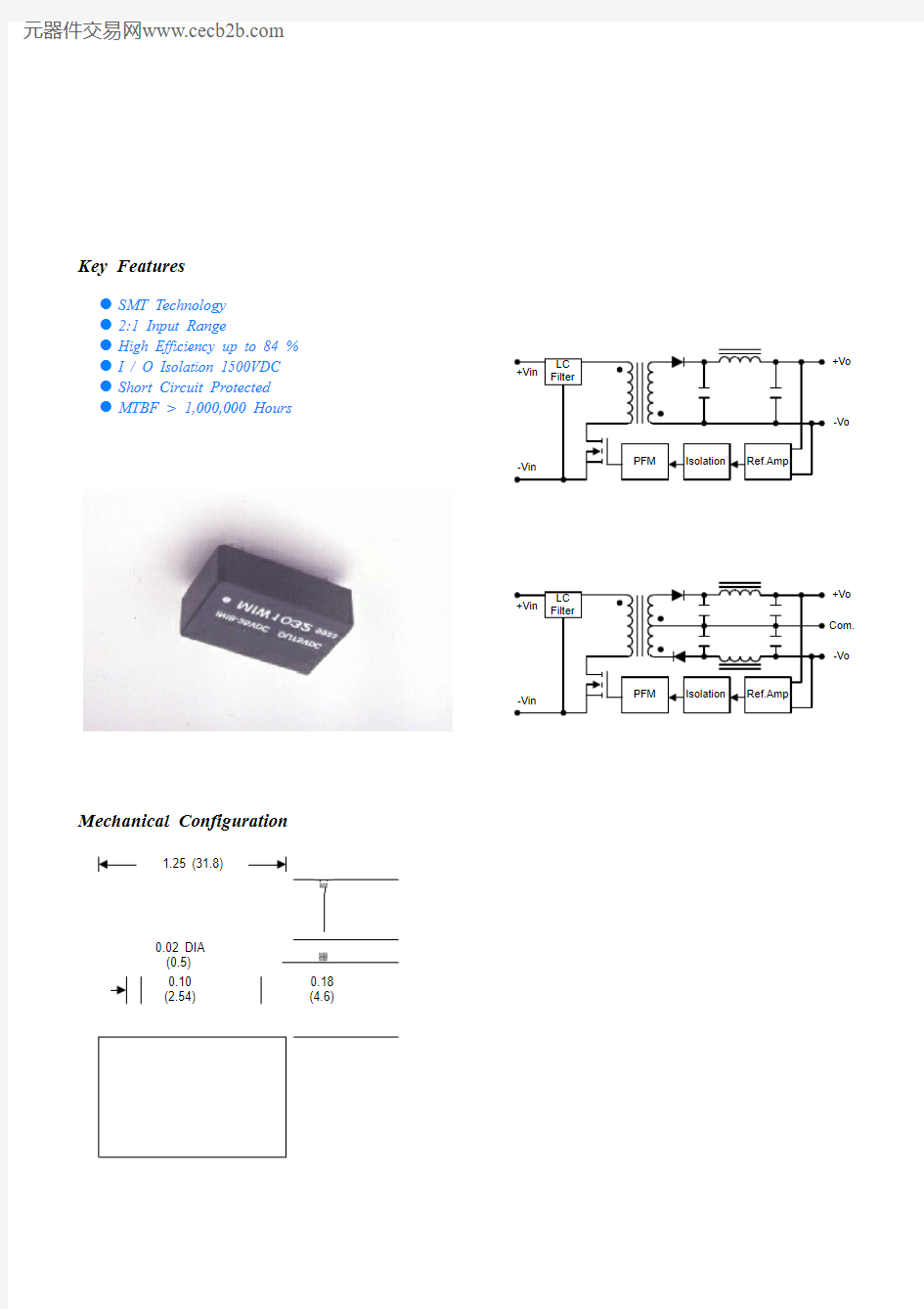
Key Features
l SMT Technology
l2:1 Input Range
l High Efficiency up to 84 % l I / O Isolation 1500VDC
l Short Circuit Protected
l MTBF > 1,000,000 Hours
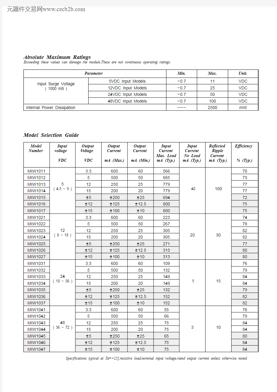
Mechanical Configuration
0.18 (4.6)
mW
2500
---
Internal Power Dissipation
VDC 100-0.748VDC Input Models
VDC 50-0.724VDC Input Models VDC 25-0.712VDC Input Models VDC 11-0.75VDC Input Models Input Surge Voltage
( 1000 mS )
Unit.Max.Min.Parameter
Absolute Maximum Ratings
Exceeding these values can damage the module.These are not continuous operating ratings.
Specifications typical at Ta=+25],resistive load,nominal input voltage,rated output current unless otherwise noted.
84
75
{10
{100
{15
MIW1047
8475{12.5{125{12MIW10468065{25{250{5MIW104584752020015MIW104484752525012MIW10437966505005MIW10427610
3
55606003.3 48( 36 ~ 72 )MIW104182152{10{100{15MIW103782152{12.5{125{12MIW103679132{25{250{5MIW1035841492020015MIW1034841492525012MIW103379132505005MIW10327615
5
109606003.3 24( 18 ~ 36 )MIW103180313{10{100{15MIW102780313{12.5{125{12MIW102677271{25{250{5MIW1025823052020015MIW1024823052525012MIW102378267505005MIW10227430
20
223606003.312( 9 ~ 18 )MIW102175800{10{100{15MIW101775800{12.5{125{12MIW101672694{25{250{5MIW1015777792020015MIW1014777792525012MIW101373685505005MIW101270100
40
566606003.35( 4.5 ~ 9 )
MIW1011Efficiency % (Typ.)Reflected Ripple Current mA (Typ.)
Input Current No Load mA (Typ.)
Input Current Max. Load mA (Typ.)
Output Current mA (Min.)
Output Current mA (Max.)
Output Voltage VDC Input voltage VDC
Model Number
Model Selection Guide
Free-Air Convection
Cooling
%
95
------Humidity ]+125----40Storage Temperature ]+71----25Operating Temperature Unit Max.Typ.Min.Conditions
Parameter
Environmental Specifications
kHz
---300
---Switching Frequency
pF 10065---100KHz,1V
Isolation Capacitance M[------1000500VDC Isolation Resistance VDC ------150060 Seconds Isolation Voltage Unit Max.Typ.Min.Conditions Parameter
General Specification
Continuous
Output Short Circuit
%/]
{0.02
{0.01
---Temperature Coefficient %{5{3---Transient Response Deviation uS 500300---50% Load Step Change Transient Recovery Time %------120Over Load
mV rms.15------Ripple & Noise (20MHz)mV P-P 100------Over Line,Load & Temp.Ripple & Noise (20MHz)mV P-P 6045---Ripple & Noise (20MHz)%{0.5{0.2---Io=10% to 100%Load Regulation %{0.5{0.2---Vin=Min. to Max.Line Regulation %{1.0{0.5---Dual Output Balance Load
Output Voltage Balance %{1.0{0.5---Output Voltage Accuracy Unit Max.Typ.Min.Conditions
Parameter
Output Specifications
Pi Filter
Input Filter
mW 2000
1000
---Short Circuit Input Power A 1------All Models
Reverse Polarity Input Current 3422---48V Input Models
1711---24V Input Models 8.56.5---12V Input Models 43.5---5V Input Models
Under Voltage Shortdown
36241648V Input Models 1812824V Input Models 974.512V Input Models
VDC 4.543.55V Input Models Start Voltage
Unit Max.Typ.Min.Model Parameter
Input Specifications
Typical Applications
Derating Curve
Connecting Pin Patterns
(2.54 mm / 0.1 inch grids )
Single Output
Dual Output
NOTE:
1. Specifications typical at Ta=+25],resistive load,nominal input voltage,rated output current unless otherwise noted.
2. Transient recovery time is measured to within 1% error band for a step change in output load of 50% to 100%.
3. When measure output ripple & noise,an external 0.1uF ceramic capacitor is recommended to be placed from +Vout to -Vout (single output) and each output to common (dual output).
4. Other input and output voltage may be available,Please contact factory.
5. Specifications subject to change without notice.
135mA Slow - Blow Type
350mA Slow - Blow Type
700mA Slow - Blow Type
1500mA Slow - Blow Type
48V Input Models 24V Input Models 12V Input Models 5V Input Models Input Fuse Selection Guide