用于碰撞被动安全性CAE分析FEM建模手册
车身模型建模要求
一般要求
General Requirements
1. The parts shall be modelled using linear (3 or 4 noded) shell elements.
2. The parts shall be modelled on the mid surface. If the delivered geometry is not a mid surface representation, the geometry shall be modified to represent the mid surface.
3. No elements are allowed to cross the “symmetry” line y=0 (nodes shall be positioned on y=0)
4. The shell elements shall be consistently defined.
5. The parts shall be modelled in the following unit settings:
? Length in millimetres (mm)
? Time in second (s)
? Mass in tonne
? Force in Newton
6. Each part shall have one unique PID, with the following exceptions:
? Parts made of tailored blanks shall be divided into different PIDs according to the
different thickness and material qualities of the parts.
? Extruded parts shall be divided into different PIDs according to the different thickness and materials of extrusion.
? The thickness at different locations on a cast/moulded part
7. The preferred naming convention as below:
ST3700=1234567_A1A_3.5_B-Pillar
material drawing no drawing rev thickness part name
8. All parts with identical materials properties shall refer to the same MID.
9. One model shall be used for all crash simulation
建模要求
Meshing Guideline
1. Deformation area shall be mesh with a average length 10mm. Deformation area
shall be mesh with a minimum length of not less than 5mm. Maximum length shall not exceed 12mm.
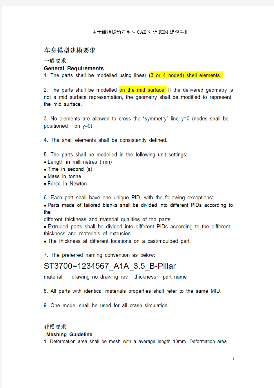
注:变形区域:
正面碰撞:A柱与B柱中间位置以前的所有零件及其某些零件的前部(车门除外),另外前端吸能部件,包括纵梁前段、翼子板支撑结构等的平均单元长度为8 mm;
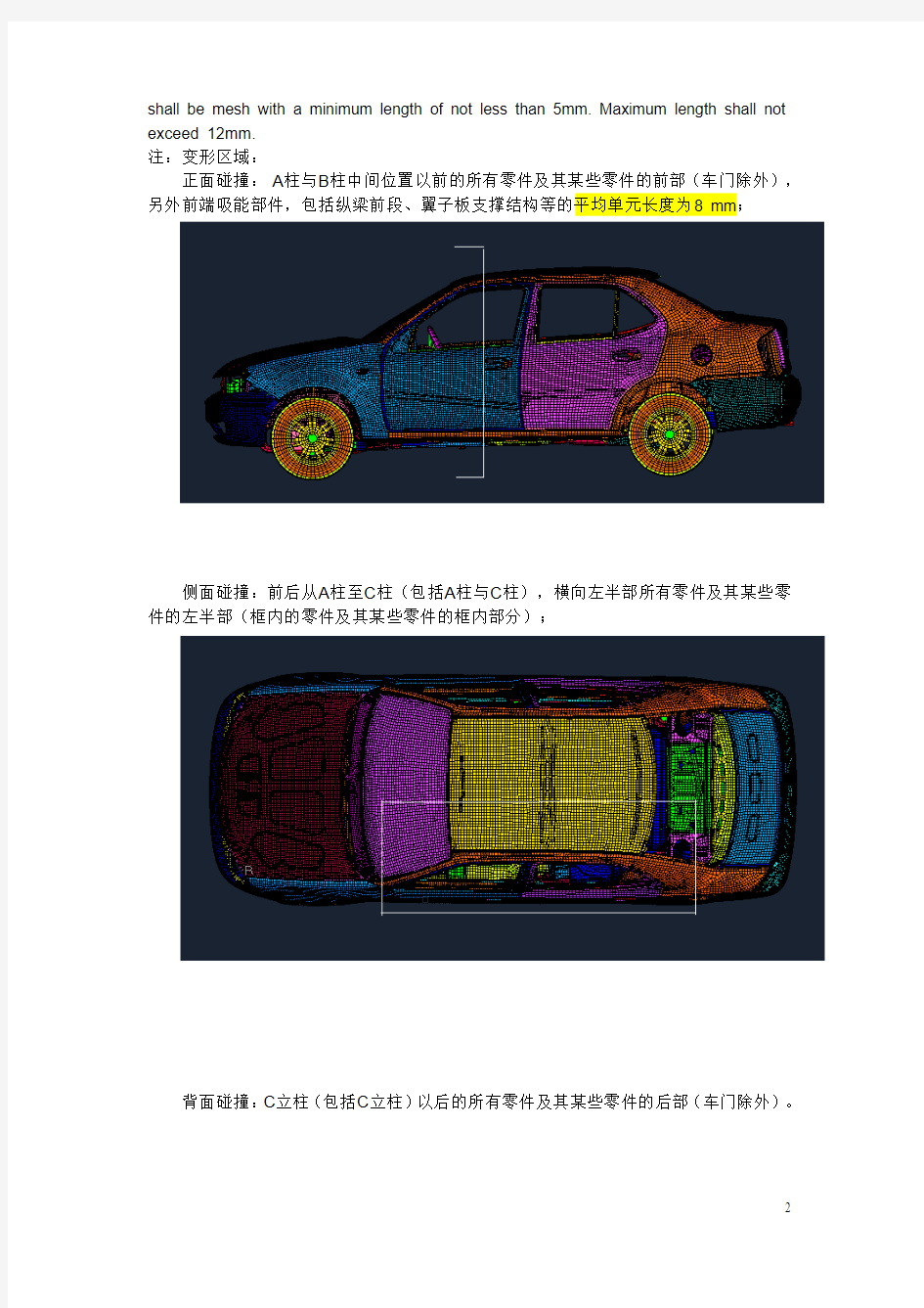
侧面碰撞:前后从A柱至C柱(包括A柱与C柱),横向左半部所有零件及其某些零件的左半部(框内的零件及其某些零件的框内部分);
背面碰撞:C立柱(包括C立柱)以后的所有零件及其某些零件的后部(车门除外)。
2.Noneformation area shall be mesh with a average length 15mm. All parts shall be mesh with a minimum length of not less than 5mm. Maximum length shall not exceed 18mm.
3. No penetrations are allowed in the FE model. FE mode shall be global penetration check . (part thickness scale is 0.65.)
4. Element type: QUAD4 and TRIA3 (max 10% of the full model)
Skewness < 60
Warping < 15
Crash Time Step* >8.1e-07
Internal Angle Min Max
QUAD 40 140
TRIA 30 120
Jacobian > 0.5
* Crash time step for part B-pillar system, longitudinal, bumper system is 6.0e-7
? The part shall be completely meshed. Un-meshed areas shall not exist
? A “free edge” check shall be performed to verify that there are no
”cracks” in the mesh.
? A “shell element normal” check shall be performed to verify that the normals are consistently defined
? No duplicate grid point numbers shall exist.
? No duplicate element numbers shall exist
? No duplicate structural elements shall exist. A duplicate element is defined as an element of the same type and attached to the same grid points as another element.
? Avoid packing triangles together to the same grid point
6. Modelling of fillet
? If the radius of the fillet is smaller than 5mm – no representation of the fillet
? If the radius of the filler is =/> 5mm, a minimal of one element in fillet is modelled.
7. Modelling of flanges
? Spotwelded flanges shall be modelled according to the figure below:
? Try to keep the original angle of the flange. In (a), the flange has a new angle, which is not recommended. The recommended practice is to model the
flange as in (b). This is for assembly reasons; flanges with large angular differences may yield poor welding elements
8. Modelling of hem flanges
? Hem flanges can be recognized by that the part is folding around itself (see figure below)
? Hem flanges should be model as figure below:
9. Modelling of holes
a) Boltholes
? For boltholes, 6 or more nodes around is required around the perimeter of the bolthole.
? The outer perimeter of washers, distances and nuts in the bolt joint shall be projected on the part and modelled using preferably 6 or more nodes around
the projected perimeter. In cases where the average element length is small compared to the size of the washer, it is allowed to use more than one row of elements between the outer and the inner washer perimeter. If the outer perimeter of washers, distances and nuts in the bolt joint is not known, acircle with centre in point C and a diameter of 2.0×D min (D min = minimum
diameter of bolt hole) may be used.
? It is allowed to slightly modify the perimeter of either the bolthole or the projected one of washers, distances and nuts in the bolt, if that improves the element quality around the bolthole.
? If the minimum diameter of the hole is smaller than the minimum element length (5mm), the hole shall not be modelled.
b) Rivet holes
? Rivet holes shall not be modelled
10. Modelling of spotweld
? Spotweld are modelled as PLINK in pamcrash model. PLINK is defined by one independent node describing the location of the spotweld as well as the parts which is needed to be spotwelded. The location of spotweld to be defined in VIP file
PLINK
? For arc welding, the position of the arc welding shall be represented by a node. This node to be modelled with TIED CONTACT (TYPE 32) –“Node to Element”
12. Modelling for glue
? Modelling of glue is by SOLID (PENTA/HEXA). The solid is to be made grid to grid to its connecting parts.
13.铰接
? 厚度不同的铸造铰链体用SOLID (PENTA/HEXA)单元模拟,其余用壳单元模拟。
?较销用spring单元模拟,spring单元只有三个移动自由度方向的刚度,三个转动自由度方向的刚度为零。
?较销与铰链体之间用rigid单元连接。
动力传动系统模型建模要求(1天)
General
? Each part of the engine components to be modelled separately into different PIDs ? Engine package can be separated into a few different categories as per below: a) ENGINE:
? Engine block
? Cylinder Head
? Cylinder Cover
? Oil pan
b) AGGREGATES:
? Generator
? Water pump
? Air conditioning compressor
? Oil Filter
? Pulleys, etc
c) INJECTION SYSTEM:
? Manifold
? Air duct
? Air filter
? Ignition system
d) ENGINE BAY COMPONENTS:
? Water tanks
? Battery
? Brake booster, brake cylinder, brake fluid tank
? ABS
? Fuse box
e) GEARBOX
? Gearbox
? Drive shaft
? Differential
f) EXHAUST SYSTEM:
? Extractor
? Catalytic converter
? Pipes
? Silencers
? Brackets/Hooks
g) ENGINE MOUNTING
h) COOLER:
? Radiator, Air condition cooler ? Fan, Cage
? Brackets etc
Meshing Guideline
1. Engine
? Meshing size 15~20mm
? Only outer surface is mesh
? To avoid hourglass issues, the ribs are to be modelled with 2 element rows.
?发动机本体在分析中作为刚体处理,但必须保证单元质量,为此可以作适当的几何简化处理
2. Aggregates
? Meshing size is 10mm
? These parts are mostly not deformable but there could be a possible rupture to its brackets ? Brackets have to be modelled middle surface with true thickness
? Aggregates can be model with outer shell.
? To avoid hourglass issues, the ribs are to be modelled with 2 element rows.
3. Injection system and engine bay components
? Meshing size is 10mm
? Parts to be modelled with outer surface
4. Gearbox
? Meshing size is 15~20mm
? Parts to be modelled with outer surface
5. Exhaust system
? Meshing size is 10mm
? Exhaust manifold/extractor and catalytic converter is modelled with outer shell
? Pipes, silencer and its ribs and to be model with middle surface
? All parts for exhaust system to be connected grid to grid.
? The compartment in the silencer has to be modelled in rib (please see figure below)
6. Engine mounting
? Meshing size is 10mm
? Engine mounting to be modelled with middle surface
?橡胶垫采用弹簧单元模拟
7. Cooler
? Meshing size is 10mm
? Fan, fan cage, pipes need to be modelled with shells
? Honeycomb on the cooler/radiator to be modelled with SOLID elements. ? A minimum of 3 layers of solid is modelled over the thickness of cooler.
底盘系统模型建模要求
一般要求
底盘系统模型包括
? 转向系统
转向拉杆
转向助力器
齿轮结构
转向柱
转向盘
支架
? 悬架系统
轮胎
羊角
摆臂
弹簧
减振器
橡胶垫
建模要求
1、转向系统
?转向拉杆用BA R和BEAM单元模拟
?转向拉杆套筒采用尺寸为10mm壳单元模拟
?转向助力器与齿轮系统只建壳体,采用尺寸为10mm壳单元模拟?转向柱采用BEAM单元模拟
?转向柱套筒采、支架、转向盘用尺寸为10mm壳单元模拟
2、悬架系统
悬架系统
?轮胎采用气袋模型模拟,因此采用尺寸完15MM的壳单元建立封闭体,轮毂采用尺寸为
20MM的壳单元作弹性体处理。
?连接摆摆臂、轮毂、悬架、转向拉杆等的羊角采用RIGID单元作为刚性体处理,在其原点附质量单元,其质量为羊角本身质量加制动系统的质量。
?板壳件摆臂采用壳单元,实体件摆臂采用SOLID单元。
?螺旋弹簧和橡胶垫的弹性属性采用BAR单元模拟,螺旋弹簧外形轮廓采用壳单元模拟,周围弹性材料处理。
?减振器外形轮廓与弹簧托架采用壳单元模拟。
座椅模型建模要求
Meshing Guideline
Seat position
? The seat must be positioned in the middle for both sliding rail axis (x-axis) and its vertical height axis (z-axis)
Seat Foam
? Average element length is 20mm. Minimum element
length is 4mm.
? Warpage is 15 deg
? Seat foam and backrest foam are model in PENTA and
HEXA SOLID only
? The foam is model with the dummy (EUROSID II v2.2 released 10.12.2004) sitting on it according to regulation ECE R95. (Please see figure below)